Dinstar DAG1000-1S User manual
DAG1000-1S/2S/4S User Manual
Copyright©2011-2017 Dinstar
I
DAG1000-1S/2S/4S Analog Telephone Adapter
User Manual V1.0
Dinstar Technologies Co., Ltd.
Address: 9th Floor, Guoxing Building, Changxing Road, Nanshan District, Shenzhen, China
Postal Code: 518052
Telephone: +86 755 61919966
Fax: +86 755 2645 6659
Emails: sales@dinstar.com, support@dinstar.com
Website: www.dinstar.com

DAG1000-1S/2S/4S User Manual
Copyright©2011-2017 Dinstar
II
Preface
Welcome
Thanks for choosing the DAG1000-1S/2S/4S Analog Telephone Adapter for VoIP! We hope
you will make full use of this rich-feature analog telephone adapter (ATA). Contact us if you
need any technical support: 86-0755-26456110/112.
About This Manual
This manual provides information about the introduction of the analog telephone adapter, and
about how to install, configure or use it. Please read this document carefully before install the
ATA.
Intended Audience
This manual is aimed primarily at the following people:
Users
Engineers who install, configure and maintain the ATA.
Revision Record
Document Name
Document Version
Firmware Version
DAG1000-1S/2S/4S Analog Telephone
Adapter User Manual V1.0
V1.0 (2016/12/12)
2.19.10.01
Conventions
ATA or device mentioned in this document refers to the DAG1000-1S, DAG1000-2S or
DAG1000-4S analog telephone adapter. Those words in red are the contents that users need to
pay attention to.

Contents
DAG1000-1S/2S/4S User Manual
Copyright©2011-2017 Dinstar
III
Contents
1Product Introduction ......................................................................................................................1
1.1 Overview .....................................................................................................................................................1
1.2 Application Scenario ...................................................................................................................................1
1.3 Product Appearance......................................................................................................................................2
1.3.1 Appearance of DAG1000-1S ...............................................................................................................2
1.3.2 Appearance of DAG1000-2S ...............................................................................................................3
1.3.3 Appearance of DAG1000-4S ...............................................................................................................3
1.4 Features & Functions...................................................................................................................................4
1.4.1 Key Features .......................................................................................................................................4
1.4.2 Physical Interfaces .............................................................................................................................4
1.4.3 Voice Capabilities & Fax .....................................................................................................................4
1.4.4 FXS......................................................................................................................................................5
1.4.5 VoIP.....................................................................................................................................................5
1.4.6 Software Features................................................................................................................................5
1.4.7 Supplementary Services.......................................................................................................................6
1.4.8 Environmental.....................................................................................................................................6
1.4.9 Maintenance........................................................................................................................................6
2Quick Installation............................................................................................................................7
2.1 Installation Attentions...................................................................................................................................7
2.2 Installation Steps ..........................................................................................................................................7
2.3 Network Connection.....................................................................................................................................7
2.3.1 Network Connection Diagram under Route Mode................................................................................7
2.3.2 Network Connection Diagram under Bridge Mode ..............................................................................8
2.4 Preparations for Login..................................................................................................................................9
2.4.1 Log In Web Interface ...........................................................................................................................9
3Basic Operation.............................................................................................................................10
3.1 Methods to Number Dialing .......................................................................................................................10
3.2 Call Holding...............................................................................................................................................10
3.3 Call Waiting ...............................................................................................................................................10
3.4 Call Transfer...............................................................................................................................................10
3.4.1 Blind Transfer....................................................................................................................................10
3.4.2 Attended Transfer ..............................................................................................................................11

Contents
DAG1000-1S/2S/4S User Manual
Copyright©2011-2017 Dinstar
IV
3.5 Function of Flash-hook...............................................................................................................................11
3.6 Description of Feature Code.......................................................................................................................12
3.7 Send or Receive Fax...................................................................................................................................13
3.7.1 Fax Mode Supported .........................................................................................................................13
3.7.2 Explanation of T.38 and Pass-through................................................................................................13
3.8 Function of RST Button..............................................................................................................................14
3.9 Query IP Address and Restore Default Setting ............................................................................................14
4Configurations on Web Interface ................................................................................................15
4.1 Navigation Tree..........................................................................................................................................15
4.2 Status & Statistics.......................................................................................................................................15
4.2.1 System Information ...........................................................................................................................16
4.2.2 Registration.......................................................................................................................................18
4.2.3 TCP/UDP Statistics............................................................................................................................19
4.2.4 RTP Session.......................................................................................................................................19
4.2.5 CDR..................................................................................................................................................19
4.2.6 Record Statistics................................................................................................................................20
4.3 Quick Setup Wizard....................................................................................................................................20
4.4 Network .....................................................................................................................................................20
4.4.1 Local Network...................................................................................................................................20
4.4.2 VLAN(Virtual Local Area Network).............................................................................................23
4.4.3 DHCP Option....................................................................................................................................24
4.4.4 QoS...................................................................................................................................................24
4.4.5 LAN Qos...........................................................................................................................................25
4.4.6 DHCP Server (Route Mode)..............................................................................................................25
4.4.7 DMZ Host (Route Mode)...................................................................................................................26
4.4.8 Forward Rule (Route Mode)..............................................................................................................27
4.4.9 Static Route (Route Mode) ................................................................................................................27
4.4.10 Firewall (Route Mode).....................................................................................................................28
4.4.11 ARP.................................................................................................................................................29
4.5 SIP Server ..................................................................................................................................................29
4.6 Port ............................................................................................................................................................32
4.7 Advanced ...................................................................................................................................................34
4.7.1 FXS Parameter ..................................................................................................................................34
4.7.2 Media Parameter................................................................................................................................36
4.7.3 SIP Parameter....................................................................................................................................37
4.7.4 Fax Parameter....................................................................................................................................44
4.7.5 Digit Map..........................................................................................................................................45

Contents
DAG1000-1S/2S/4S User Manual
Copyright©2011-2017 Dinstar
V
4.7.6 System Parameter..............................................................................................................................46
4.8 Call & Routing ...........................................................................................................................................48
4.8.1 Port Group.........................................................................................................................................48
4.8.2 IP Trunk.............................................................................................................................................50
4.8.3 Routing Parameter.............................................................................................................................51
4.8.4 IP Tel Routing...............................................................................................................................52
4.8.5 Tel IP/Tel Routing.........................................................................................................................53
4.8.6 IP IP Routing ................................................................................................................................54
4.9 Manipulation..............................................................................................................................................54
4.9.1 IP Tel Callee .................................................................................................................................55
4.9.2 Tel IP/Tel Caller............................................................................................................................56
4.9.3 Tel IP/Tel Callee ...........................................................................................................................57
4.10 Management.............................................................................................................................................59
4.10.1 TR069 .............................................................................................................................................59
4.10.2 SNMP..............................................................................................................................................60
4.10.3 Syslog..............................................................................................................................................63
4.10.4 Provision .........................................................................................................................................63
4.10.5 Cloud server ....................................................................................................................................64
4.10.6 User Manage ...................................................................................................................................65
4.10.7 Remote Server.................................................................................................................................65
4.10.8 Action URL.....................................................................................................................................66
4.11 Security....................................................................................................................................................66
4.11.1 WEB ACL .......................................................................................................................................66
4.11.2 Telnet ACL ......................................................................................................................................67
4.11.3 Passwords........................................................................................................................................67
4.11.4 Encrypt............................................................................................................................................68
4.12 Tools.........................................................................................................................................................68
4.12.1 Firmware Upload.............................................................................................................................68
4.12.2 Data Backup....................................................................................................................................69
4.12.3 Data Restore....................................................................................................................................70
4.12.4 Ping Test..........................................................................................................................................70
4.12.5 Tracert Test......................................................................................................................................71
4.12.6 Outward Test ...................................................................................................................................71
4.12.7 Network Capture .............................................................................................................................72
4.12.8 Factory Reset...................................................................................................................................74
4.12.9 Device Restart .................................................................................................................................74
5Glossary..........................................................................................................................................75
1 Product Introduction
DAG1000-1S/2S/4S User Manual
Copyright©2011-2017 Dinstar
1
1 Product Introduction
1.1 Overview
DAG1000-1S/2S/4S is a multi-functional analog telephone adapter which offers seamless
connectivity between IP-based telephony networks and legacy telephones (POTS), fax
machines and PBX systems.
The device provides 1, 2 or 4 FXS port(s), fax over IP and a built-in high-speed NAT router.
These powerful features and good voice quality make the device ideal for personal use and
suitable for various application environments such as SOHO and small enterprises.
Moreover, with automatic provisioning and centralized management system, the device is
easy for maintenance and deployment.
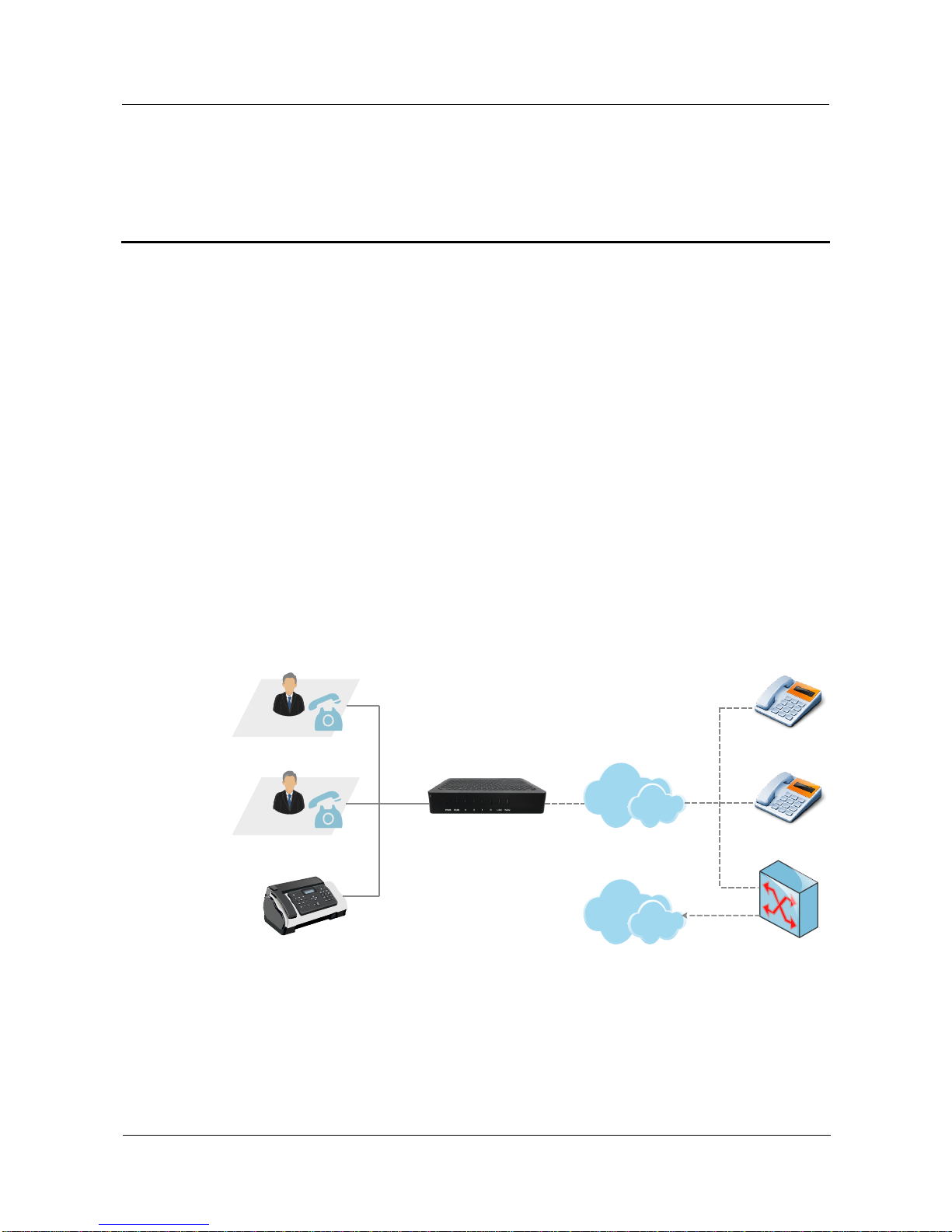
1.2 Application Scenario
The application scenario of DAG1000-1S/2S/4S analog telephone adapter is shown as
follows:
Figure 1-1 Application Scenario of DAG1000-1S/2S/4S
DAG1000-2S
LAN
Analog Phone
POTS
IP Phone
SIP Server
Fax Machine
PSTN
1 Product Introduction
DAG1000-1S/2S/4S User Manual
Copyright©2011-2017 Dinstar
2
1.3 Product Appearance
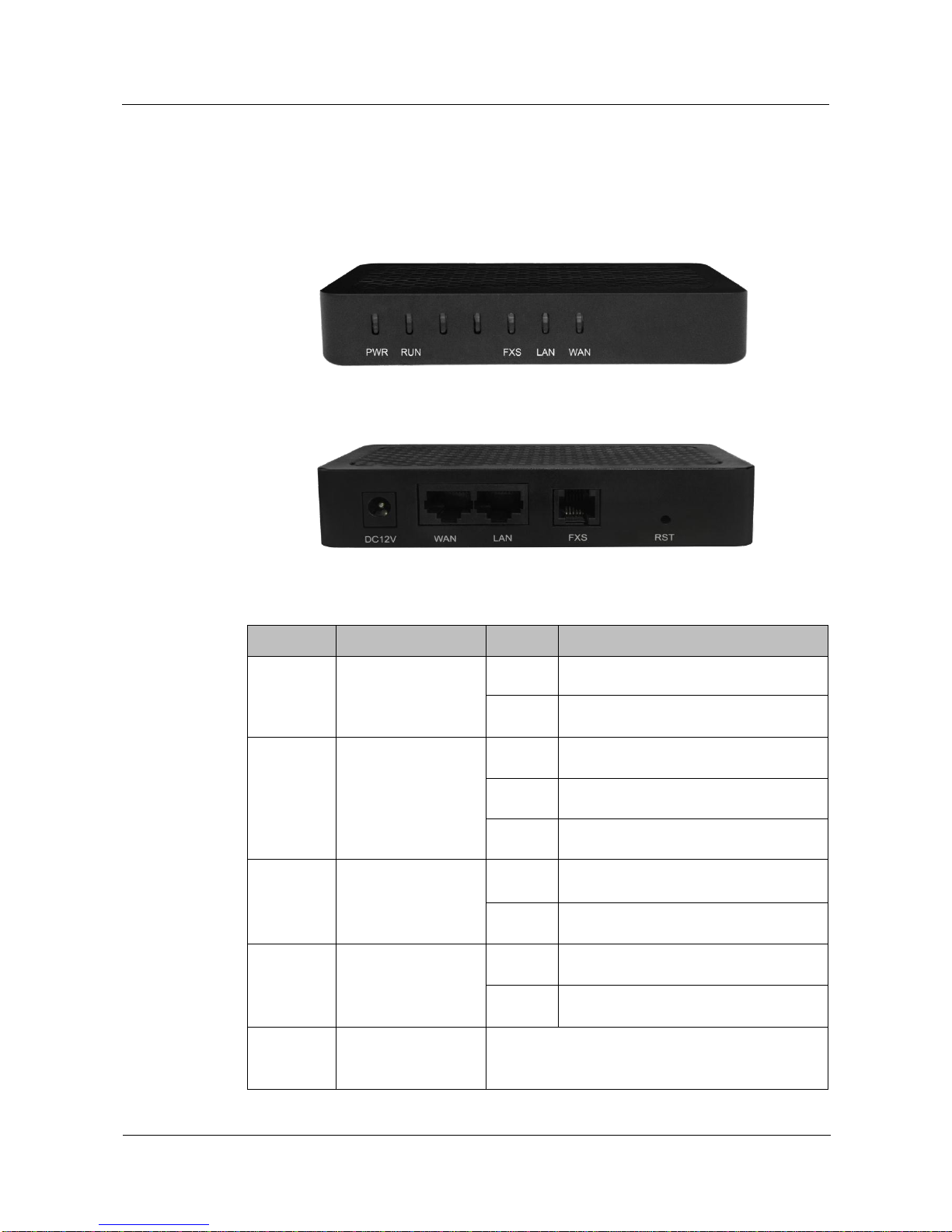
1.3.1 Appearance of DAG1000-1S
Front View:
Back View:
Table 1-1 Description of Indicators and Interfaces of DAG1000-1S
Indicator
Definition
Status
Description
PWR
Power Indicator
On
The device is powered on.
Off
There is no power supply or power
supply is abnormal.
RUN
Running Indicator
Slow
Flashing
The device is running normally
Fast
Flashing
SIP account is registered successfully
Off
The device is running improperly
FXS
FXS In-use Indicator
On
FXS port is currently occupied by a call
Off
FXS port is idle or faulty
WAN/LAN
Network Link
Indicator
Green
Flashing
The device is properly connected to
network
Off
The device is not connected to network
or network connection is improper
RST
Reset Button
Used to reset the gateway to factory default settings.
After pressing the reset button, you need to restart
the gateway manually.

1 Product Introduction
DAG1000-1S/2S/4S User Manual
Copyright©2011-2017 Dinstar
3
1.3.2 Appearance of DAG1000-2S
Front View:
Back View:
For the description of indicators and interfaces of DAG1000-2S, please refer to Table 1-1.
1.3.3 Appearance of DAG1000-4S
Front View:
Back View:
For the description of indicators and interfaces of DAG1000-4S, please refer to Table 1-1.

1 Product Introduction
DAG1000-1S/2S/4S User Manual
Copyright©2011-2017 Dinstar
4
1.4 Features & Functions
1.4.1 Key Features
Cost-effective ATAwith 1, 2 or 4 FXS ports
Fax over IP (T.38 and Pass-Through)
Support IPv4 and IPv6
TR069 and SNMP
Elastix and Broadsoft Certification
Multiple codecs: G.711A/U, G.723.1, G.729A/B, G.726
Fully compatible with leading IMS/NGN and SIP-based IP telephony systems
1.4.2 Physical Interfaces
Telephone Port
DAG1000-1S: 1 FXS port (RJ11)
DAG1000-2S: 2 FXS ports (RJ11)
DAG1000-4S: 4 FXS ports (RJ11)
Ethernet Interfaces
DAG1000-1S/2S/4S:
1 WAN, 10/100Mbps (RJ45)
1 LAN, 10/100Mbps (RJ45)
1.4.3 Voice Capabilities & Fax
Codecs: G.711a/μ law, G.723.1, G.729A/B, G.726
Silence Suppression
Comfort Noise Generator(CNG)
Voice Activity Detection(VAD)
Echo Cancellation: G.168 with up to 128ms
Adaptive (Dynamic) Jitter Buffer
Hook Flash
Adjustable Gain Control
Programmable Gain Control
FAX: T.38 and Pass-through
Modem/POS
DTMF: SIP Info/RFC2833/Inband
VLAN 802.1P/802.1Q

1 Product Introduction
DAG1000-1S/2S/4S User Manual
Copyright©2011-2017 Dinstar
5
Layer 3 QoS and DiffServ
1.4.4 FXS
FXS Connector: RJ11
Dial Mode: DTMF and Pulse
Pulse: 10 and 20 PPS
Caller ID: DTMF/FSK CLI Presentation
Max Cable Length: 3km
Reversed Polarity
Programmable Call Progress Tone
1.4.5 VoIP
Protocols: SIP v2.0 (UDP/TCP), RFC3261, SDP, RTP(RFC2833), RFC3262, RFC3263,
RFC3264, RFC3265, RFC3515, RFC2976, RFC3311
RTP/RTCP, RFC2198, RFC1889
SIP over TLS
RFC4028 Session Timer
RFC3266 IPv6 in SDP URI
RFC 3581 NAT.rport
Primary/Backup SIP Server
Outbound Proxy
DNS SRV/AQuery/NATPR Query
SIP Trunk
Early Media/EarlyAnswer\
NAT: STUN, Static/Dynamic NAT
1.4.6 Software Features
Hunting Group
Web ACL
Telnet ACL
Action URL
PPPoE/IPv4/IPv6
Digitmap
Bandwidth Optimization
Routing Rules based on Prefixes
Caller/Called Number Manipulation

1 Product Introduction
DAG1000-1S/2S/4S User Manual
Copyright©2011-2017 Dinstar
6
1.4.7 Supplementary Services
Call Waiting and Call Holding
Call Forwarding(Unconditional/Busy/No Reply)
Call Transfer (Blind & Attended)
Warm/Immediately Hotline
Do-not-disturb
Three Parties Conversation (3-way Conference)
Message Waiting Indicator
1.4.8 Environmental
Power Supply: 12V DC, 1A
Power Consumption: <5W
Operating Temperature: 0 ℃~ 45 ℃
Storage Temperature: -20 ℃~80 ℃
Humidity: 10%-90% (Non-Condensing)
Dimensions:126×76×25mm(W/D/H)
Unit Weight:<=0.2kg
Compliance: UL
1.4.9 Maintenance
SNMP V1/V2/V3
TR069
Auto Provisioning (HTTP/FTP/TFTP)
Web/Telnet
Configuration Backup/Restore
Firmware Upgrade via Web
CDR
Syslog
Ping, Tracert Test
Network Capture
Outward Test (GR909 Standard)
NTP/Daylight Saving Time
IVR Local Maintenance
Cloud-based Management

2 Quick Installation
DAG1000-1S/2S/4S User Manual
Copyright©2011-2017 Dinstar
7
2 Quick Installation
2.1 Installation Attentions
To avoid unexpected accident or device damage, please read the following instructions before
installing the DAG1000 device:
The device accepts DC input voltage of 12V. Please ensure stable and safe power supply;
To reduce the interference to telephone calls, please separate power cables from telephone
lines.
To guarantee stable running of the device, please make sure that there is enough network
bandwidth.
For better heat dissipation, please place the device on a flat surface and do not pile up with
other devices.
2.2 Installation Steps
Connect the power adapter to the power jack of the DAG1000 device;
Connect telephone line to the FXS port(s);
Connect network cable to the LAN port and WAN port (please refer to 2.3 Network
Connection);
2.3 Network Connection
DAG1000-1S/2S/4S works in two network modes: route mode and bridge mode. When it is
under the route mode, the IP address of WAN port must be at different network segment from
that of the LAN port. But when it is under the bridge mode, the IP address of WAN port is the
same with that of LAN port.
2.3.1 Network Connection Diagram under Route Mode
Under the route mode, the default IP address of WAN port is a DHCP IP address, while the
default IPaddress of the LAN port is a static IP address, namely 192.168.11.1.

2 Quick Installation
DAG1000-1S/2S/4S User Manual
Copyright©2011-2017 Dinstar
8
Figure 2-1 Network Connection Diagram under Route Mode
Router
192.168.1.XXX
192.168.11.1
192.168.11.XXX
DAG1000-2S
DHCP Server
DC12V
WAN
LAN
FXS0
FXS1
RST
IP Network
Note: The IP address of LAN port of the DAG1000 device and the IP address of PC must be
at the same network segment, while that of WAN port is at a different network segment.
2.3.2 Network Connection Diagram under Bridge Mode
Under the Bridge mode, the IP address of WAN port is the same with that of LAN port.
Generally, when the device works under the bridge mode, the IP address of the device has
been modified. In the following diagram, it is assumed that the IP address has been modified
into 172.16.80.1.
Figure 2-2 Network Connection Diagram under Bridge Mode
172.16.80.XXX
Switch/Router
172.16.80.1
DAG1000-2S
DC12V
WAN
LAN
FXS0
FXS1
RST

2 Quick Installation
DAG1000-1S/2S/4S User Manual
Copyright©2011-2017 Dinstar
9
Note: The IP address of PC and that of WAN port of the DAG1000-1S/2S/4S device are at the
same network segment.
2.4 Preparations for Login
Firstly, connect the device to network according to the above network diagrams, and connect
a telephone to the FXS port. Then dial *158# to query the IP address of the LAN port (default
IP is 192.168.11.1).
Secondly, modify the IP address of the PC to make it at the same network segment with the
LAN port of the device.
Thirdly, check the connectivity between the PC and the device. Click Start Run of PC and
enter cmd to execute ‘ping 192.168.11.1’to check whether the IP address of LAN port runs
normally.
2.4.1 Log In Web Interface
Open a web browser and enter the IP address of LAN port (the default IP is 192.168.11.1).
Then the login GUI will be displayed.
You also can enter the IP address of WAN port, but it’s required to modify the IP address of
PC to make it at the same network segment with WAN port and ‘Access Web by WAN’ is
enabled on the Advanced System Parameter page.
It is suggested that you should modify the username and password for security consideration.
Figure 2-3 Login GUI
Both the default username and password are admin. Click Login to enter into the web
interface.

3 Basic Operation
DAG1000-1S/2S/4S User Manual
Copyright©2011-2017 Dinstar
10
3 Basic Operation
3.1 Methods to Number Dialing
There are two methods to dial telephone number or extension number:
Dial the called number and wait for 4 seconds for dialing timeout, or dial the called
number directly (the system will judge whether the dialing is completed according to
Digitmap and Regular Expression dialplans).
Dial the called number and press #.
3.2 Call Holding
If a calling party places a call to a called party which is otherwise engaged, and the called
party has the call holding feature enabled, the called party is able to switch to the new
incoming call while keeping the current call holding on by dialing *# or pressing the flash
button/flash hook.
When the called party dials *# once again or presses the flash button/ flash hook once again,
he or she will switch back to the first call.
3.3 Call Waiting
If a calling party places a call to a called party which is otherwise engaged, and the called
party has the call waiting feature enabled, the calling party will hear a IVR voice ‘Please hold
on, the subscriber you dialed is busy’ and the called party will hear three beeps if waiting tone
is enabled.
By pressing the flash button or the flash hook, the called party is able to switch between the
new incoming call and the current call.
3.4 Call Transfer
3.4.1 Blind Transfer
Blind transfer is a call transfer in which the transferring party connects the call to a third party
without notifying the third party.

3 Basic Operation
DAG1000-1S/2S/4S User Manual
Copyright©2011-2017 Dinstar
11
Example: A gives a call to B and B wants to blindly transfer the call to C. Operation
instructions are as follows:
1. A dials the extension number of B;
2. The extension of B rings, and B picks up the phone. Then A and B go into conversation;
3. B presses the flash button (or flash hook), and dial *87* after hearing a dialing tone to
trigger blind transfer. Then B dials the extension number of C (end up with #).
4. The extension of C rings, B hangs up the phone and C picks up the phone. Then C and A
goes into conversation.
Note:
On the ‘Advanced Feature Code’page, blind transfer should be enabled.
If B hears continuous busy tones after he dials the extension number of C, it means the call has
timed out.
3.4.2 Attended Transfer
Attended transfer is a call transfer in which the transferring party connects the call to a third
party after he confirms that the third party agrees to answer the call.
Example: A gives a call to B and B wants to attended transfer the call to C. Operation
instructions are as follows:
1. A dials the extension number of B;
2. The extension of B rings, and B picks up the phone. Then A and B go into conversation;
3. B presses the flash button (or flash hook), and then dials the extension number of C (end up
with #).
; Then one of the following situations will happen:
a. If C answers the call and accepts the transfer, B will hand up the phone, and then C and
A go into conversation.
b. If the extension of C cannot be reached or if C rejects the call, B needs to press the flash
button to resume the call with A.
3.5 Function of Flash-hook
Assume A and B are in a call conversation:
If B presses the flash hook, and then dial the number of C, B and C go into conversation and
meanwhile the call between B and A is kept holding.
Then, if B presses the flash hook and dials 1, the conversation will switch back to Aand B; if
B presses the flash hook and dials 2 , the conversation will switch to B and C; if Apresses the
flash hook and dials 3, the conversation will switch to A , B and C (which is named

3 Basic Operation
DAG1000-1S/2S/4S User Manual
Copyright©2011-2017 Dinstar
12
‘three-way calling’).
3.6 Description of Feature Code
DAG1000-1S/2S/4S provides convenient telephone functions. Connect a telephone to the
FXS port and dial a specific feature code, and you can query corresponding information.
Code
Corresponding Function
*159#
Dial *159# to query WAN IP
*158#
Dial *158# to query LAN IP
*114#
Dial *114# to query the phone number of a FXS port
*115#
Dial *115# to query the phone number of a FXS port group
*168#
Dial *168# to query the register status of a FXS port
*157*
Dial *157*0 to set route mode; dial *157*1 to set bride mode
*150*
Dial *150*1 to set IP address as static IP address; dial *150*2 to set IP
address as DHCP IP address
*152*
Dial *152* to set IPv4 address, for example:
Dial *152*192*168*1*10# to set IPv4 address as 192.168.1.10
*156*
Dial *156* to set IPv4 gateway, for example:
Dial *156*192*168*1*1# to set IPv4 gateway as 192.168.1.1
*153*
Dial *153* to set IPv4 netmask, for example:
Dial *153*255*255*0*0*# to set IPv4 netmask as 255.255.0.0
*170#
Dial *170# to increase the sound volume of a FXS port
*171#
Dial *171# to decrease the sound volume of a FXS port
*160*
Dial *160*1# to allow HTTP WAN access, Dial *160*0# to deny
HTTPWAN access
*165*
Dial *165*000000# to restore username/password and network
configuration to factory defaults
*111#
Dial *111# to restart the device
*47*
Dial *47* to allow call through IP address, for example:
Dial *47*192*168*1*1# to allow to call through the IP address of
192.168.1.1
*51#
Dial *51# to enable the call waiting service
*50#
Dial *50# to disable the call waiting service
*87*
Dial *87* to trigger blind transfer, for example:

3 Basic Operation
DAG1000-1S/2S/4S User Manual
Copyright©2011-2017 Dinstar
13
Dial *87*8000#, and you can blind transfer to the extension number
8000
*72*
Enable unconditional call forwarding service. Example: Dial
*72*8000, and calls will be unconditionally forwarded to extension
number 8000
*73#
Disable unconditional call forwarding service
*90*
Enable the ‘call forwarding on busy’service. Example: Dial *90*8000,
and calls will be forwarded to extension number 8000 when the called
number is busy
*91#
Disable the ‘call forwarding on busy’service
*92*
Enable the ‘call forwarding on no reply’service. Example: Dial
*92*8000, and calls will be forwarded to extension number 8000 when
there is no reply from the called number
*93#
Disable the ‘call forwarding on no reply’service
*78#
Enable the ‘No Disturbing’service
*79#
Disable the ‘No Disturbing’service
*200#
Dial *200# to access voicemail
Note:
A voice prompt indicating successful configuration will be played after each configuration
procedure. Please do not hang up the phone until hearing this voice prompt.
3.7 Send or Receive Fax
3.7.1 Fax Mode Supported
T.38(IP-based)
T.30(Pass-Through)
Adaptive Fax Mode (automatically match with the peer fax mode)
3.7.2 Explanation of T.38 and Pass-through
T.38 is an ITU recommendation for allowing transmission of fax over IP networks in real time.
Under the T.38 mode, analog fax signal is converted into digital signal and fax signal tone is
restored according to the signal of peer device. Under the T.38 mode, fax traffic is carried in
T.38 packages.

3 Basic Operation
DAG1000-1S/2S/4S User Manual
Copyright©2011-2017 Dinstar
14
T 3.0 (Pass-through): Under the pass-through mode, fax signal is not converted and fax
traffic is carried in RTP packets. It uses the G.711 A or G711U codec in order to reduce the
damage to fax signal.
Adaptive Fax Mode:automatically match with the fax mode of the peer device.
3.8 Function of RST Button
Press the RST button of DAG1000-1S/2S/4S for a moment, the running indicator will turn
from “slow flashing” into “no flashing”, and then turn into “slow flashing” again. That means
the device has been restored to factory defaults.
3.9 Query IP Address and Restore Default Setting
Query IPAddress:
After connecting a telephone to the FXS port, you can dial *158# to query the IP address of
LAN port and dial *159# to query the IP address of WAN port.
Reset Password:
1. On the “Security Passwords” page of the Web interface, you can reset username and
password.
2. You can also reset password through the Cloud platform.
3. Connect a telephone with the DAG1000 device, and then dial *165*000000# to restore
username/password and network configuration to factory defaults.
Restore Device to Default Settings:
1. Connect a telephone with the DAG1000 device, and then dial *166*000000# to restore all
configurations to factory defaults.
2. Press the RST button for a moment, the running indicator will turn from “slow flashing”
into “no flashing”, and then become “slow flashing” again. That means all configurations
of the device has been restored to factory defaults.
3. On the “Tools Factory Reset” page of Web interface, click Apply to restore the
configurations of the device to factory defaults.
4 Configurations on Web Interface
DAG1000-1S/2S/4S User Manual
Copyright©2011-2017 Dinstar
15
4 Configurations on Web Interface
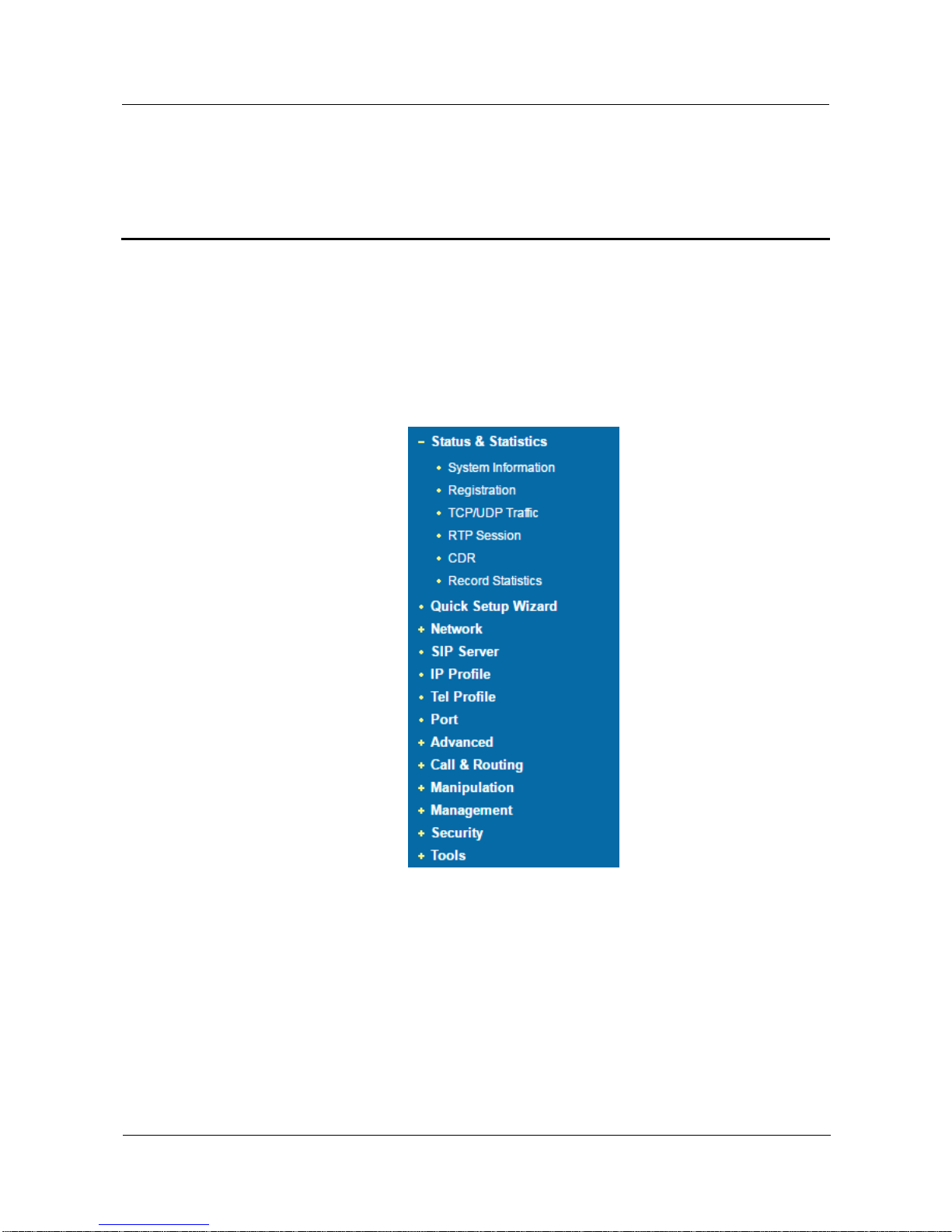
4.1 Navigation Tree
The web management system of the DAG1000-1S/2S/4S VoIP device consists of the
navigation tree and detailed configuration interfaces.
Choose a node of the navigation tree to enter into a detailed configuration interface.
Figure 4-1 Navigation Tree of Web Interface
Note: When the device works under the bridge mode, configuration items including "Routing
Configuration" , "DHCP Service", "DMZ Host", "Forward Rules" and "Static Routing" and "ARP"
will not be displayed.
4.2 Status & Statistics
The ‘Status & Statistics’menu mainly displays all kinds of information. It includes the
following sub-menus: System Information, Registration, TCP/UDP Traffic, RTP Session,
CDR and Record Statistics.
Other manuals for DAG1000-1S
1
This manual suits for next models
2
Table of contents


