Lanpro LP-575G User manual

1
LP575G_UG_ENB01W
LP-575G
54MB High Power Wireless USB Adapter
Installation Guide
LanPro, The natural choice in Networking and LanProfessional are US registered Brands.
LanPro (LanProfessional) products are made in one of the following Countries: USA, Taiwan, Thailand,
China, and Canada. The exact country of origin is unknown

2
COPYRIGHT & TRADEMARKS
Specifications are subject to change without notice LanPro Inc. Copyright ©
2008 LanPro Inc. All rights reserved. Other brands and product names are
trademarks or registered trademarks of their respective holders.
No part of the specifications may be reproduced in any form or by any means
or used to make any derivative such as translation, transformation, or
adaptation without permission from LanPro Inc. Copyright © 2008 LanPro Inc.
All rights reserved.
FCC STATEMENT
This equipment has been tested and found to comply with the limits for a class
B digital device, pursuant to part 15 of the FCC Rules. These limits are
designed to provide reasonable protection against harmful interference in a
residential installation.
This equipment generates, uses and can radiate radio frequency energy and, if
not installed and used in accordance with the instructions, may cause harmful
interference to radio communications. However, there is no guarantee that
interference will not occur in a particular installation. If this equipment does
cause harmful interference to radio or television reception, which can be
determined by turning the equipment off and on, the user is encouraged to try
to correct the interference by one or more of the following measures:
•Reorient or relocate the receiving antenna.
•Increase the separation between the equipment and receiver.
•Connect the equipment into an outlet on a circuit different from that to
which the receiver is connected.
•Consult the dealer or an experienced radio/TV technician for help.

3
This device complies with Part 15 of the FCC Rules. Operation is subject to the
following two conditions:
1. This device may not cause harmful interference.
2. This device must accept any interference received, including
interference that may cause undesired operation.
Changes or modifications to this unit not expressly approved by the party
responsible for compliance could void the user's authority to operate the
equipment.
FCC RF Radiation Exposure Statement:
This equipment complies with FCC RF radiation exposure limits set forth for an
uncontrolled environment. This device and its antenna must not be co-located
or operating in conjunction with any other antenna or transmitter.
IMPORTANT NOTE:
FCC Radiation Exposure Statement:
This device has been tested for compliance with FCC RF Exposure (SAR) limits
in the typical laptop computer configuration and this device can be used in
substantially similar laptop computers with side mounted PCMCIA slots. This
device cannot be used with handheld PDAs (personal digital assistants) or
other portable host devices. This device and its antenna must not be
co-located or operated in conjunction with any other antenna or transmitter.
CE Declaration of Conformity
For the following equipment: LP-575G
Is here with confirmed to comply with the requirements set out in the Council
Directive on the Approximation of the Laws of the Member States relating to
Electromagnetic Compatibility (89/336/EEC), Low-voltage Directive

4
(73/23/EEC) and the Amendment Directive (93/68/EEC), the procedures given
in European Council Directive 99/5/EC and 89/3360EEC.
The equipment was passed. The test was performed according to the following
European standards:
•EN 300 328 V.1.4.1 (2003).
•EN 301 489-1 V.1.4.1 (2002) / EN 301 489-17 V.1.2.1 (2002).
•EN 60950-1: 2001.
European standards dictate maximum radiated transmit power of 100mW EIRP
and frequency range 2.400-2.4835GHz; In France, the equipment must be
restricted to the 2.4465-2.4835GHz frequency range and must be restricted to
indoor use.

5
CONTENT
Package Contents.................................................................................................................... 6
Chapter 1: Introduction......................................................................................................... 6
1.1 Overview of the product........................................................................................... 6
1.2 Features.......................................................................................................................... 7
1.2 LED Status..................................................................................................................... 7
Chapter 2: Installation Guide.............................................................................................. 8
2.1 Software Installation................................................................................................. 8
2.1.1 Overview................................................................................................................. 8
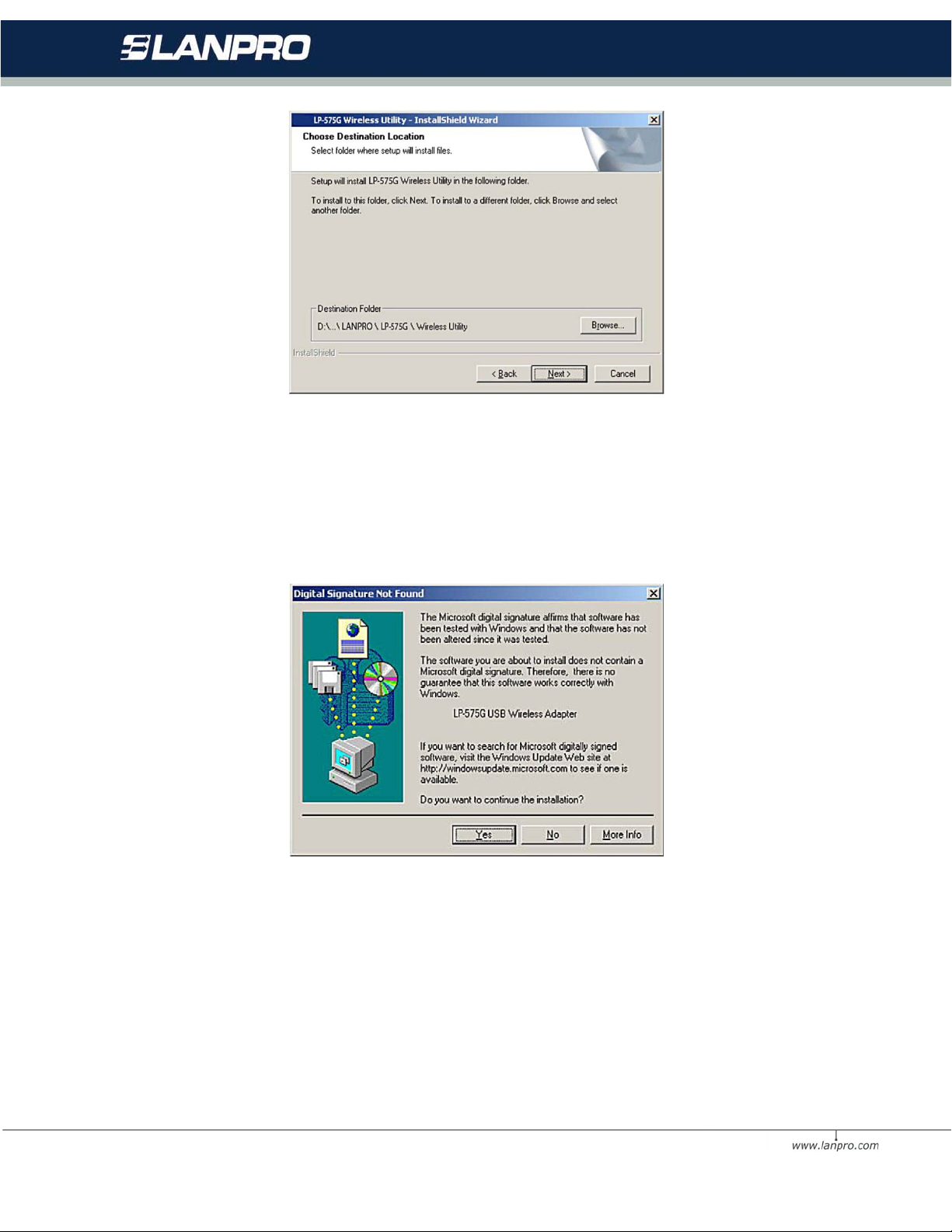
2.1.2 Software Installation for Windows 2000................................................... 8
2.2 Hardware Installation.............................................................................................. 11
2.3 Uninstall Software.................................................................................................... 12
2.3.1 Uninstall the driver software from your PC............................................... 12
Capítulo 3: Configuración................................................................................................... 13
3.1 Profile........................................................................................................................... 14
3.1.1 Add or Edit a Configuration Profile.............................................................. 16
3.2 Link Status.................................................................................................................. 19
3.3 Site Survey................................................................................................................. 20
3.4 Statistics................................................................................................................... 20
3.5 Advanced..................................................................................................................... 21
3.6 About............................................................................................................................ 22
3.7 An example for application.................................................................................... 23
Appendix A: Specifications................................................................................................. 24
Appendix B: Glossary........................................................................................................... 25
Appendix C: Contact Information..................................................................................... 27

6
Package Contents
The following contents should be found in your box:
•One LP-575G USB Wireless Adapter
•One USB extension cable
•Quick Installation Guide
•One LP-575G Wireless Adapter Resource CD, including:
Utility and Drivers
User Guide
Other Helpful Information
Note: If any of the listed contents is damaged or missing, please contact the
retailer from whom you purchased
Chapter 1: Introduction
1.1 Overview of the product
The LANPRO LP-575G USB Wireless Adapter gives you the flexibility to install
your PC or notebook PC in the most convenient location available, without the
cost of running the network cables.
Its auto-sensing capability allows high packet transfer up to 54Mbps for
maximum throughput, or dynamic range shifting to lower speeds due to
distance or operating limitations in an environment with a lot of
electromagnetic interference. It can also interoperate with all 11Mbps wireless
(802.11b) products. Your wireless communications are protected by up to 128-
bit WEP and WPA encryption, so your data stays secure.

7
1.2 Features
•Complies with IEEE802.11g, IEEE802.11b standards
•Supports WPA data security, IEEE802.1x authentication, TKIP/AES
encryption, 64/128-bit WEP encryption
•Supports 54/48/36/24/18/12/9/6Mbps or 11/5.5/3/2/1Mbps wireless
LAN data transfer rates
•Provides USB interface
•Supports Ad-Hoc and Infrastructure modes
•Supports roaming between access points when configured in
Infrastructure mode
•Eases configuration and provides monitoring information
•Supports Windows 98SE, Me, 2000, XP, Vista and Linux, Macintosh
•Internal Antenna
1.2 LED Status
The LED on the top of this card indicates Link/Act status. It blinks at green
light when sending and receiving data.

8
Chapter 2: Installation Guide
2.1 Software Installation
2.1.1 Overview
The 575G Setup Wizard will guide you through the installation procedure for
Windows 98SE, Me, 2000, XP, Vista and Linux, Macintosh. The Setup Wizard
will guide you install the Utility and drivers.
If you install the hardware before the software, you will be prompted “Found
New Hardware Wizard”, click the Cancel button, and run the Setup Wizard
program on the CD-ROM.
The Setup steps for Windows 98SE, Me, 2000, XP, Vista and Linux, Macintosh
are very similar. The following setup steps are for windows 2000.
2.1.2 Software Installation for Windows 2000
1. Insert the Resource CD into your CD-ROM drive, click the Start button
and choose Run. In the field that appears, enter F:\XXX\Setup.exe (if
“F” is the letter of your CD-ROM drive; XXX presents the setup program
path, which is labeled on the Resource CD), figure 2-1 should then
appear.
2. You can click the Cancel button to end the installation on the Preparing
Setup screen, figure 2-1. Otherwise, the Setup Wizard will display a
screen similar to that shown in figure 2-2 after a moment.

9
Figure 2-1 Preparing Setup
3. To continue, click the Next button on the screen, figure 2-2. Click the
Cancel button to end the Installation.
Figure 2-2 Start Setup
4. Click Browse to change the destination location for the software in
figure 2-3 Click Next to continue the Installation.

10
Figure 2-3 Choose Destination Location
5. While files are copying, you will see a warning box shown in figure 2-4.
Please select YES to continue installation. Our drivers have been tested
thoroughly, and are able to work with the operating system.
Figure 2-4 Windows 2000 Warning Box
6. After the files have been successfully copied, the screen in figure 2-5 will
appear. Click the Finish button to finish the wizard.

11
Figure 2-5 Finish
7. After installing the software, Please plug the adapter into your PC. If you
need instructions as to how to do this, please refer to section 2.2
Hardware Installation. If you have plugged it into you PC already, please
un-plug it and plug it back in. The OS will automatically detect the
adapter and automatically setup the driver for the adapter. If it does
not, please follow the setup steps to finish the driver installation.
After installing the driver successfully, you should see an icon , or ,
appear in your system tray.
2.2 Hardware Installation
1. Connect one end of the USB cable to the Adapter. (Or the 575G directly
to the USB computer port).
2. Connect the other end of the USB cable to the USB port on your
computer. Because the Adapter gets its power from the host, there is no
external power supply. The LED should light up when the Adapter is
plugged in and the PC is on.

12
2.3 Uninstall Software
2.3.1 Uninstall the driver software from your PC
1. On the Windows taskbar, click the Start button, point to Settings, and then
click Control Panel.
2. Double-click the System icon, click on the Hardware tab in the System
window.
Click on the Device Manager button, double-click Network Adapters, and
then right-click LP-575G USB
Wireless Adapter.
Figure 2-6 Uninstall Driver
3. Click Uninstall..., shown in above figure 2-6, the system will uninstall
the driver software of the adapter from your PC.

13
Uninstall the utility software from your PC
1. On the Windows taskbar, click the Start button, point to Settings, and then
click Control Panel
2. Double-click the Add/Remove Programs icon, find the LP-575G program
from the installed program list,
highlight it and click the Remove button.
3. Following the Install Shield Wizard will uninstall the utility software from
your PC.
Chapter 3: Configuration
The LP-575G USB Wireless Adapter can be configured by its utility. This section
describes how to configure your USB Wireless Adapter for wireless connectivity
on your Wireless Local Area Network (WLAN) and use the data security
encryption features.
After the Adapter's driver and utility has been installed, the adapter’s tray icon
, or, will appear in your system tray. It means the utility is running on
your system. If the utility does not run, you can run the utility by clicking:
Start> Program> LanPro > LP-575G WIRELESS UTILITY> LP-575G
Wireless Utility. If the icon still does not appear, the driver or utility may be
installed incorrectly or the adapter is unplugged, please try again.
Icon means the connection has been established. Icon means there is
no connection.
Double-click the icon and the configuration screen of the utility will appear.
You can also run the utility by clicking: Start> Program> LanPro > LP-575G

14
WIRELESS UTILITY> LP-575G Wireless Utility. The utility provides a
complete and easy to use set of tools to:
•Display current status information
•Edit and add configured profiles
•Display current diagnostics information
The section below introduces these above capabilities.
Note: If your OS is Windows XP, you can use Windows XP to configure the
wireless network settings. (To use this function, you must upgrade the OS with
sp1).
If you want to use Windows XP to configure wireless network settings, just exit
the utility. Right-click the icon at the bottom of the screen, and click Exit
to exit the utility.
3.1 Profile
Click the Profile tab of the utility and the Profile screen will appear, figure
3-1. The Profile screen provides tolos to:
•Add a Profile
•Delete a profile
•Edit a profile
•Activate a profile

15
Figure 3-1 Profile Tab
To create a new profile, click the Add button on the Profile tab, the Profile
configuration screen will appear as
shown in figure 3-2.
To edit a profile, highlight the desired profile name on Profile Name list,
and click the Edit button, the Profile configuration screen will appear shown in
figure 3-1.
To delete a profile, highlight the desired profile name on Profile Name list,
and click the Delete button.
To switch to another profile, highlight the desired profile name on Profile
Name list, and click the Activate button.
Note: Do not forget to click the Apply button when you create a new profile
for connection.

16
3.1.1 Add or Edit a Configuration Profile
To add a new configuration profile, click Add button on the Profile Management
tab. To modify a configuration profile, select the configuration from the Profile
list and click Edit
The Profile Management dialog box will display a screen similar to that shown
in Figure 3-2.
1. Edit the Configuration tab
•Profile Name - Identifies the configuration profile. This name must be
unique. Profile names are not
•case-sensitive.
•SSID - The IEEE 802.11 wireless network name. This field has a
maximum limit of 32 characters.
•PSW(Power Save Mode)
•CAM(Constantly Awake Mode) - Continuous Access Mode.
•PSW(Power Saving Mode) - Power Saving mode.
•Network Type - Displays the wireless mode, either Ad-hoc or
Infrastructure mode
•Preamble - Specifies the preamble setting in 802.11b. The
default setting is Auto Switch (access point
•mode), which allows both short and long headers in the 802.11b
frames. The adapter can only use short
•radio headers if the access point supports and uses them.
•RTS Threshold - Default is 2312.
•Fragment Threshold - Default is 2312.
•Ad-hoc mode - Displays the wireless mode, either Only 802.11B
or 802.11B/G mode.

17
•Channel - Shows the current channel in use. This field determines
which operating frequency will be
•used.
Figure 3-2 Add Profile – configuration
2. Edit the Authentication and Security tab

18
Figure 3-3 Add Profile – configuration
•Authentication Type - Three options, Open System, Shared-Key
System or LEAP.
•802.1x Setting - It enables when Authentication Type is setting to
WPA.
•Encryption - Displays which encryption type that the driver is using.
When you select Open System,
•Shared-Key System as Network Authentication, there are two
options: WEP and Disabled. If you select
•WPA-PSK as Network Authentication, there are TKIP and AES
options instead of WEP and Disabled.
•Wep Key - Key #1, Key #2, Key #3, Key #4, the Key groups. You can
enter 10 hexadecimal digits (any combination of 0-9, a-f, A-F) or 5
ASCII characters for 64-bit (also called 40bits) encryption. You can enter
26 hexadecimal digits (any combination of 0-9, a-f, A-F) or 13 ASCII
characters for 128-bit (also called 104bits) encryption.

19
3.2 Link Status
The Link Status tab displays the adapter's current status.
Figure 3-4 Link Status
The following table describes the items found on the Network Status screen.
•Status - Shows whether the station is connected to the wireless
network, if not connected, display RF is closed; if connected, display AP
name and BSSID.
•Extra Info - Shows link status and the current channel in use.
•Link Speed - Shows the current max Transfer rate, unit is Mbit/sec.
•Throughput - Displays Tx and Rx rate, unit is Kbits/sec.
•Link Quality - Shows the quality of the signal.
•Signal Strength - Shows the strength of the signal.

20
3.3 Site Survey
Click the Site Survey tab of the Utility and the Site Survey screen will
appear, figure 3-5. On the Site Survey screen you can scan the Available
Infrastructure and Ad Hoc Networks.
Figure 3-5 Site Survey tab
Haga clic en Rescan para refrescar la lista en cualquier momento. Resalte un
SSID y haga clic en Connect para conectarse a una red disponible.
3.4 Statistics
The Statistics tab shows receiving and transmitting statistical information for
the following receive and transmit diagnostics for frames received by or
transmitted to the wireless network adapter. Click the Reset Counter button
to reset the count of the statistics information.
Table of contents
Other Lanpro Adapter manuals
Popular Adapter manuals by other brands

Clas Ohlson
Clas Ohlson UTC-CA01-R manual

TRENDnet
TRENDnet TPL-302E user guide

Lenovo
Lenovo ThinkPad 90W Slim AC/DCCombo Adapter user guide

Sun Microsystems
Sun Microsystems LSI22320-SR installation guide

StarTech.com
StarTech.com FCREADMICRO instruction manual

ABB
ABB JOKAB SAFETY Tina 6A Original instructions