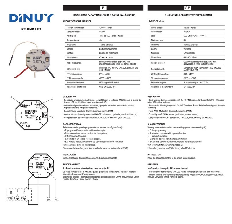
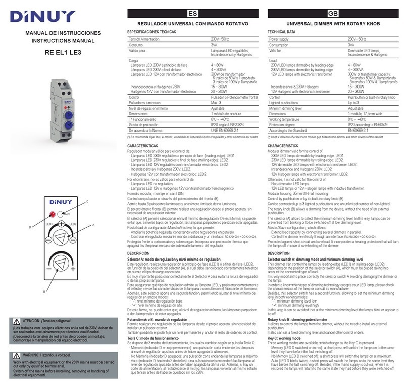
DINUY RE KNX LE1 User manual

EGB
RE KNX LE1
REGULADOR UNIVERSAL DE 1 CANAL INALÁMBRICO
ESPECIFICACIONES TÉCNICAS
Tensión Alimentación 230V~ 50/60Hz
Consumo Propio 3VA
Radio-Frecuencia Emisión codificada en 868,4MHz
Alcance de 100m (campo abierto)
Compatible con Sensores KNX-RF: PU KNX 001,
EM KNX 002 y RC KNX 001
Protección Ambiental IP20 según UNE 20234
Tª Funcionamiento 0ºC ~ +40ºC
Dimensiones 55 x 53 x 34mm
DESCRIPCIÓN
· Se trata de un regulador universal inalámbrico, compatible con el protocolo KNX-RF, para el
control de lámparas de LED regulables, incandescentes y halógenas.
· Tecnología de regulación en corte de fase, a principio (L1) ó a final (L2) de fase en función de la
posición del selector (C) y la naturaleza de la carga conectada.
· Protegido contra cortocircuitos y sobrecargas.
· Control a través de cualquier emisor KNX-RF del mercado: pulsador, mando a distancia...
· Compatible con los emisores DINUY: RC KNX 001, PU KNX 001 y EM KNX 002.
· Posibilidad de control a través de pulsador cableado (D).
· Dispone de la función Memoria (opcional).
CARACTERÍSTICAS
Selector de modos para la programación de enlaces y configuración (B):
- P: programación de un enlace del canal receptor.
- R: funcionamiento normal con función de repetidor.
- S: funcionamiento normal.
- E: borrado de un enlace del canal receptor.
- EA: borrado de todos los enlaces de los canales transmisor y receptor.
Selector de tipo de carga (C) que tiene 2 funciones:
- 1º. Seleccionar el tipo de carga:
. L1: LED a 230V~ y Halógenas 12V~ con transformador ferromagnético.
. L2: LED a 12V~ con transformador electrónico, Incandescencia y Halógenas a 230V~ y
Halógenas a 12V~ con transformador electrónico.
- 2º. Ajustar el nivel mínimo de regulación (- +). Principalmente se utiliza con lámparas LED.
De esta forma se puede evitar que al nivel de regulación mínimo las lámparas den la
impresión de estar apagas o se produzcan parpadeos.
Dispone de tecla de Programación para el enlace con otros dispositivos RF (A).
Es posible conectar un pulsador auxiliar (D) para el control local de la carga: encender, apagar y
regular.
Dispone de 2 canales RF: canal de salida (pulsador cableado) y canal de entrada (del regulador).
INSTALACIÓN
Instale el actuador de acuerdo al esquema de conexión mostrado.
La conexión del pulsador auxiliar (D) es opcional. Dependerá su instalación de si se requiere de
un pulsador de control local de la carga conectada al actuador ó de si se requiere el control
remoto vía RF de otro u otros mecanismos receptores RF asociados.
Montaje En caja de registro
Carga
Válido para Lámparas LED regulables,
Incandescencia y halógenas
Tª Almacenamiento -30ºC ~ +70ºC
Control De forma inalámbrica o/y Pulsador
cableado
De acuerdo a la Norma UNE-EN 60669-2-1
Nº canales 1 canal de salida
1 - CHANNEL UNIVERSAL WIRELESS DIMMER
TECHNICAL DATA
DESCRIPTION
· It is a wireless universal dimmer compatible with the KNX-RF protocol for the control of
dimmable LED lamps, incandescent and halogen lamps.
· Leading (L1) or Trailing (L2) edge dimming technology, depending on the position of the
selector switch (C) and the load.
· Protected against overloads and shortcircuits.
· Control by any RF-KNX sensor: pushbutton, remote control...
· Compatible with DINUYs sensors: RC KNX 001, PU KNX 001 and EM KNX 002.
· Possibility of control through wired pushbutton (D).
· Incorporates the Momory functional (optional).
CHARACTERISTICS
Working mode selector switch for the setting-up and commissioning (A):
- P: link programming.
- R: standard operation with repeater function.
- S: standard operation.
- E: one link deletion from the receiver channel.
- EA: all links deletion from the receiver and transmitter channels.
Load type selector switch (C). It has 2 functions:
- 1º. Select the load type:
· L1: 230V~ LED lamps and 12V~ halogen lamps with ferromagnetic transformer.
· L2: 12V~ LED lamps with electronic transformer, Incandescent & Halogen lamps and
12V~ Halogen lamps with electronic transformer.
- 2º. Select the minimum lighting level (- +). It is useful with LED lamps. It avoids undesirable
effects (e.g.: blinks) when the LED lamps are dimmed at low level.
It has a Programming key (A) for linking other RF devices.
It is possible to wire an auxiliary pushbutton (D) for the local control of the load: switch on/off and
dimming. Lighting pushbuttons are not alowed.
Two RF channels: output channel (wired pushbutton) and input channel (of the dimmer).
INSTALLATION
Install the actuator according to the shown wiring diagram.
The connection of an auxiliary pushbutton (D) is optional. It depends if the installation requires a
local control pushbutton on the load connected to the actuator or if requires a remote control from
one or more other linked RF receivers.
L1: Lámparas LED a 230V~
L1: Halógenas 12V~ con transfo ferromagnético
L2: LED a 12V~ con transfo electrónico
L2: Incandescencia y halógenas 230V~
L2: Halógenas a 12V~ con trafo electrónico
4W ~ 100W
200W
Máximo 5 transformadores de 50W
y 1 lámpara por trafo
250W
250W
Nivel de regulación mínimo Ajustable
Power supply 230V~ 50/60Hz
Power sonsumption 3VA
Radio-Frequency Codified trnasmission in 868,4MHz
Range up to 100m (in the free field)
Compatible with KNX-RF sensors: PU KNX 001,
EM KNX 002 & RC KNX 001
Protection degree IP20 according to UNE 20234
Working temperature 0ºC ~ +40ºC
Dimensions 55 x 53 x 34mm
Mounting Junction box
Load
Valid for Dimmable LED lamps,
Incandescent & halogen lamps
Storage temperature -30ºC ~ +70ºC
Control Wireless (KNX-RF) or
by a Wired Pushbutton
According to the Standard EN 60669-2-1
Channels 1 output channel
L1: 230V~ LED lamps
L1: 12V~ Halogens with Inductive transformer
L2: 12V~ LED lamp with Electronic transformer
L2: Incandescent & 230V~ Halogen lamps
L2: 12V~ Halogens with Electronic transformer
4W ~ 100W
200W
Up to 5 transformers of 50W
& 1 lamp/trafo
250W
250W
Minimum brightness level Adjustable
D
C
A
B
RS
E
EA
P
+ +
PROG.
230V~ 50Hz
L
N
4-250W
230V~ 50/60Hz
RE KNX LE1
L
N
R,L,C

GB E
DINUY S.A.
c/Auzolan Nº2
20303 Irún (Spain)
info@dinuy.com
www.dinuy.com
FUNCIONAMIENTO
A.- Funcionamiento a través de su pulsador auxiliar cableado (D)
Cualquier pulsación corta (<300mseg) del pulsador auxiliar, tiene como consecuencia:
- Un cambio, ON u OFF, del estado anterior en que se encontraba la carga local conectada.
- El envío, vía radio, de un mensaje de ON u OFF, en concordancia con el cambio de estado
que realiza la carga local.
Una pulsación mantenida (>300mseg) del pulsador auxiliar, tiene como consecuencia:
- Un cambio, subida o bajada, del nivel anterior de regulación en que se encontraba la carga
local conectada.
- El envío, vía radio, de un mensaje DimCtrl, en concordancia con el cambio de estado que
realiza la carga local.
El canal de salida 0 del pulsador cableado envía los objetos: Info OnOff, OnOff y DimCtrl.
B.- Funcionamiento a través de su canal receptor RF
La carga conectada al RE KNX LE1 puede gobernarse remotamente, vía radio, desde un
dispositivo transmisor RF programado.
El canal de entrada 1 del regulador responde a los objetos: Info OnOff, InfoDimValue, OnOff,
DimCtrl, DimValue, Timed, Forced y Scene.
C.- Función Memoria
Es posible configurar el receptor para que cada vez que recibe una señal de encendido se active
al máximo o a la última luminosidad que tenía antes de ser apagado (Memoria).
Para activar esta función:
1.- Con la carga apagada, colocar el selector en "R" o "S". El LED verde estará encendido.
2.- Pulse el botón "PROG" durante ~5seg. El LED verde parpadeará 3 veces.
Para desactivarla:
1.- Con la carga apagada, colocar el selector en "R" o "S". El LED verde estará encendido.
2.- Pulse el botón "PROG" durante ~5seg. El LED rojo parpadeará 3 veces.
CONFIGURACIÓN
A.- Programación de un enlace del canal receptor (P)
Para realizar un enlace del canal receptor del RE KNX LE1 con un canal transmisor de un
dispositivo KNX-RF (tecla, mando,):
1.- Poner el selector de modos del RE KNX LE1 en modo programación de enlaces,
colocándolo en la posición P. El LED verde parpadeará lentamente.
2.- Con la ayuda de un clip, presionar, brevemente, la tecla de Programación (A). El LED
verde se quedará encendido fijo. El canal receptor del RE KNX LE1 se encuentra en estos
momentos en espera de aceptar un enlace de un canal transmisor de un dispositivo RF.
3.- Poner el canal transmisor del dispositivo RF que queremos enlazar en modo programación
de enlaces, de acuerdo a las instrucciones del fabricante.
4.- Si el establecimiento del enlace tiene éxito, el LED verde comenzará a parpadear.
Si pasan 2 minutos desde que el RE KNX LE1 estuviera en modo programación sin recibir
ningún intento de enlace de un posible canal transmisor de un
dispositivo RF, el LED verde comezará a parpadear, abandonando el modo programación.
5.- Para que el RE KNX LE1 vuelva a ser operativo, situar el selector en la posición S o R.
B.- Programación de un enlace del canal transmisor
Para realizar un enlace (asociación) del canal transmisor del RE KNX LE1 con un canal receptor
de un dispositivo KNX-RF:
1.- Poner el receptor que queremos enlazar en modo programación de enlaces.
2.- A continuación, poner el RE KNX LE1 en modo programación de enlaces, colocando el
selector de modo sobre P. El LED verde parpadeará lentamente.
3.- Pulsar con un clip o similar, sobre el pulsador de configuración.
4.- Si el establecimiento del enlace tiene éxito, el LED del receptor lo indicará de alguna forma.
5.- Para que el RE KNX LE1 vuelva a ser operativo, situar el selector en la posición S o R.
C.- Borrado de un enlace del canal receptor (E)
Para borrar un enlace del canal receptor del RE KNX LE1 con un canal transmisor de un
dispositivo KNX-RF (tecla, mando,):
1.- Poner el selector de modos del RE KNX LE1 en modo borrado de enlaces, colocándolo en la
posición E. El LED rojo parpadeará lentamente.
2.- Con la ayuda de un clip, presionar, brevemente, la tecla de Programación (A). El LED
rojo se quedará encendido fijo. El canal receptor del RE KNX LE1 se encuentra en estos
momentos en espera de aceptar un desenlace de un canal transmisor de un dispositivo RF.
3.- Poner el canal transmisor del dispositivo RF que queremos borrar en modo programación de
enlaces.
4.- Si el borrado del enlace tiene éxito, el LED rojo comenzará a parpadear nuevamente.
D.- RESET: Borrado de todos los enlaces del canal receptor y del canal transmisor (EA)
Para borrar todos los enlaces del RE KNX LE1:
1.- Poner el RE KNX LE1 en modo RESET, colocando el selector de modo sobre EA. El LED
rojo parpadeará rápidamente.
2.- Pulsar con un clip la tecla de Programación (A) hasta que el LED rojo se quede fijo.
3.- A continuación, el LED rojo comenzará a parpadear de nuevo rápidamente.
E.- Modo Repetidor
El RE KNX LE1 puede, opcionalmente, realizar la función de repetidor de telegramas RF.
Esta función es útil solo en aquellas instalaciones donde se detecten problemas de comunicación
entre dispositivos RF debido a la distancia. En estos casos, un dispositivo situado entre ambos,
capaz de realizar la función repetidor (retransmisión), se convierte en una herramienta útil para
solventar este problema. No se recomienda la utilización de más de tres repetidores.
La función repetidor se activa colocando el selector de modo en la posición R. El resto
de la funcionalidad del interruptor de RF permanece sin alteración.
OPERATION
A.- Operation through the external auxiliary pushbutton (D)
Any short press (<300msec) of the auxiliary pushbutton causes:
- The change of the previous state of the load connected to the RE KNX LE1: ON or OFF.
- The transmission of an ON or OFF message, in concordance with the change of the load.
Any long press (>300msec) of the auxiliary pushbutton causes:
- The increase or decrease of the previous dimming level.
- The transmission of the telegram DimCtrl, in concordance with the change of the load.
El canal de salida 0 del pulsador cableado envía los objetos: Info OnOff, OnOff y DimCtrl.
B.- Operation though its RF receiver channel
The load connected to the RE KNX LE1 can be controlled remotely with a RF transmitter
The input channel 1 of the dimmer responds to the objects: Info OnOff, InfoDimValue, OnOff,
DimCtrl, DimValue, Timed, Forced & Scene.
C.- Memory function
Is possible to configure the receiver to each time it receives an ON signal is activated to maximum
or last level it had before turned off (Memory).
To enable this function:
1.- With the load off, set the switch to "R" or "S". The green LED will be on.
2.- Press the "PROG" key for ~ 5sec. The green LED will flash 3 times.
To disable it:
1.- With the load off, set the switch to "R" or "S". The green LED will be on.
2.- Press the "PROG" key for ~ 5sec. The red LED will flash 3 times.
COMMISSIONING
A.- Programming a link of the receiver channel (P)
To link the receiver channel of the RE KNX LE1 with the sender channel of other RF-KNX device
(pushbutton, remote control):
1.- Set the mode selector switch of the RE KNX LE1 at programming mode, placing it at P
position. The green LED verde will flicker slowly.
2.- Press the Programming key (A) with the help of a clip or something similar. The green
LED will be ON. The receiver channel of the RE KNX LE1 is now waiting to accept a link from
the transmitter channel of other RF device.
3.- Set the transmitter channel of the other RF device in link mode according to the instructions
given by the manufacturer.
4.- If the link is successful the green LED will start flickering.
In the same way, 2 minutes after the RE KNX LE1 is in programming mode without no
attempt to link a transmiter, the green LED will start flickering and it will leave the link mode.
5.- To become the RE KNX LE1 operational set the mode selector switch at S or R position.
B.- Programming a link of the transmitter channel
To link the transmitter channel of the RE KNX LE1 with the receiver channel of other RF device:
1.- Set the receiver in link mode.
2.- Set the RE KNX LE1 in programming mode, setting the knob at P position. The green LED
will flicker slowly.
3.- Press the programming pushbutton (A) with the help of a clip.
4.- If the link is successful the LED of the receiver will show it in some way.
5.- To become the RE KNX LE1 operational set the mode selector switch at S or R position.
C.- Delete a link from the receiver channel (E)
To delete a link with other RF transmitter from the receiver channel of the RE KNX LE1:
1.- Set the mode selector switch of the RE KNX LE1 at E position. The red LED will flicker
slowly.
2.- Press the programming key (A) with the help of a clip. The red LED will be ON. The
receiver channel of the RE KNX LE1 is waiting to receive the signal from the sender channel
of the other device.
3.- Set the transmitter channel of the other device in unlink mode.
4.- If the unlink is successful, the red LED will start to flicker.
D.- RESET: Delete all links from the receiver and sender channels (EA)
To delete all links from the RE KNX LE1:
1.- Set the mode selector switch of the RE KNX LE1 in RESET, placing it at EA. The red LED
will flicker quickly.
2.- Press the programming pushbutton (A) until the red LED is constantly ON.
3.- The red LED will start to flicker quickly again.
4.- To become the RE KNX LE1 operational set the mode selector switch at S or R position.
E.- Repeater mode
The RE KNX LE1 can also act as a signal repeater.
This function is useful in the installations where are problems with the coverage between the
devices because of the distance.
It is not advisable to use more than three repeaters in the same installation.
This function is activated setting the mode selector switch at R. The rest of functionality
continues without changes.
C
A
B
RS
E
EA
P
+ +
PROG.
Other DINUY Dimmer manuals
