Dionex ICS-6000 User manual

ICS-6000 Tablet Installation Instructions
This is an excerpt from the Dionex ICS-6000 Installation manual

Dionex ICS-6000 Installation Instructions
66 Doc. 22181-97001 02/18
3.9 Installing the Tablet
This section contains instructions for attaching the tablet to the DC. The
procedure requires parts from two kits:
•The Tablet Kit (P/N 22181-62020) contains the tablet and its power
supply. When the tablet is purchased from Thermo Fisher Scientific, the
ICS-6000 App is installed on the tablet at the factory and a predefined
user account is created.
•The Tablet Arm/Holder Kit (P/N 22181-62016) contains the parts
required to attach the arm and holder assembly to the DC.
Installation of a Third-Party Tablet
When the tablet is purchased separately from the Dionex ICS-6000, you are
responsible for making sure the tablet meets current specifications (see
Table 3-3).
NOTE If you do not purchase the tablet from Thermo Fisher Scien-
tific, you must also install the ICS-6000 App (see
Section 3.11.1) and manually pair the tablet and instrument
PC (see Section 3.12.2).
Specification Requirement
Table 3-3. Tablet Specifications

3 • System Setup
Doc. 22181-97001 02/18 67
3.9.1 Getting Started
1. Unpack the Tablet Kit (P/N 22181-62020). The kit contains the tablet and
tablet power supply (P/N HAZMAT-01-00136), as well as setup
instructions from the tablet vendor. (You can disregard the vendor
instructions.)
2. Unpack the Tablet Arm/Holder Kit (P/N 22181-62016). The kit contains
all the parts needed to attach the tablet arm to the DC (see Figure 3-26).
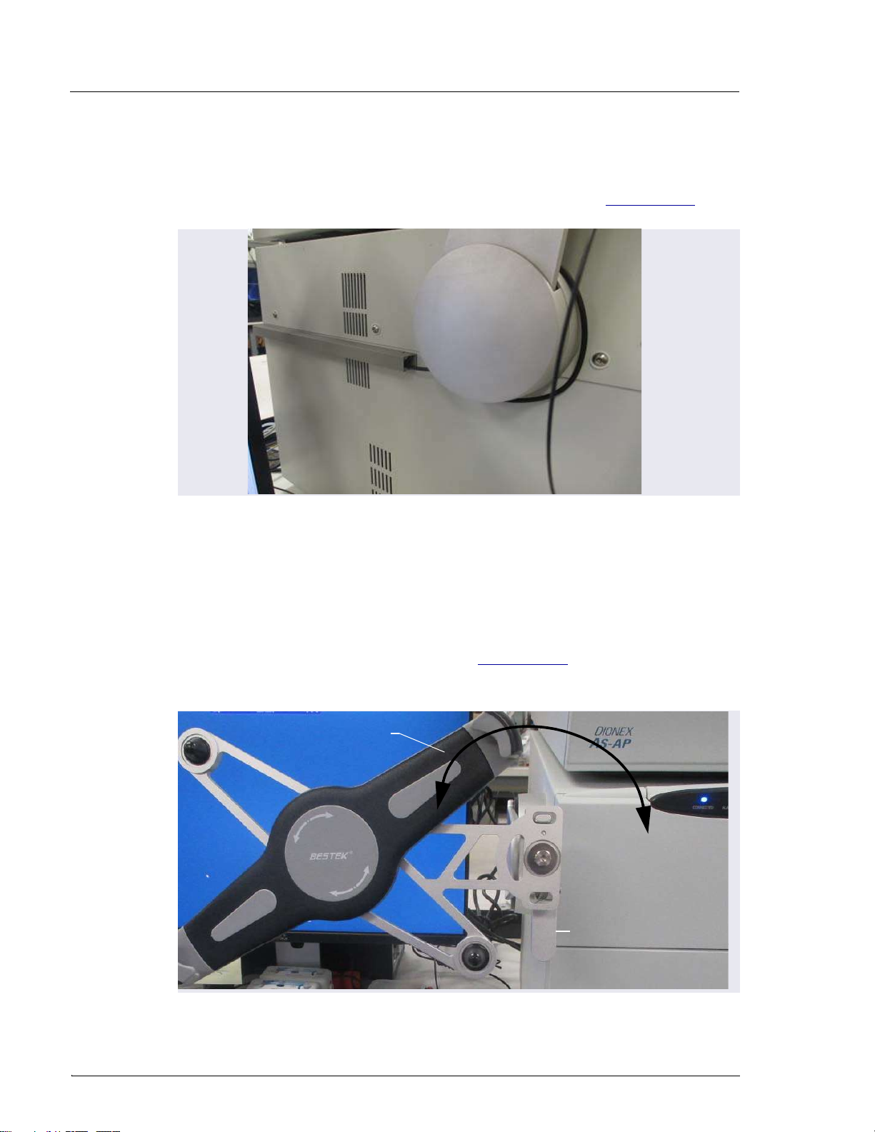
3. The mounting arm cover (P/N 22181-60500) is held in place by magnets.
Pull the cover off the mounting arm (see Figure 3-27) and set it aside.
(You will reinstall the cover later.)
Figure 3-26. Tablet Arm/Holder Kit Contents Unpacked
Figure 3-27. Removal of the Mounting Arm Cover
Arm Cover
Cable Guide
Tablet
Holder
Spiral Cable
Wraps
Tablet Tension
Grip
Wiring Duct
3 M4 Screws
Dionex ICS-6000 Installation Instructions
68 Doc. 22181-97001 02/18
3.9.2 Installing the Tablet Arm/Holder
1. Attach the mounting arm (P/N 22181-60500) to the left side of the DC:
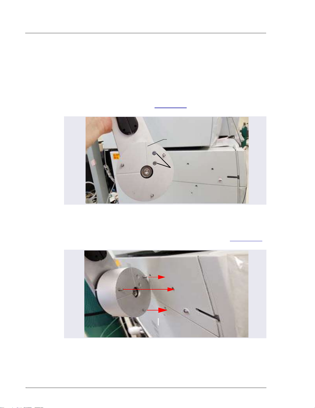
a. Note the two lines molded into the base of the tablet mounting arm,
on the inside of the arm (the side of the arm which is installed against
the DC). When installing the mounting arm, make sure the line to the
left of the two fasteners (see Figure 3-28) is in the vertical position.
b. Align the three mounting screws on the base of the mounting arm
with the three mounting holes on the side of the DC (see Figure 3-29).
Figure 3-28. Position Indicator on the Tablet Mounting Arm/Holder
Figure 3-29. Tablet Arm/Holder Mounting Screws on the DC
Vertical Position
Indicator
Fasteners
3 • System Setup
Doc. 22181-97001 02/18 69
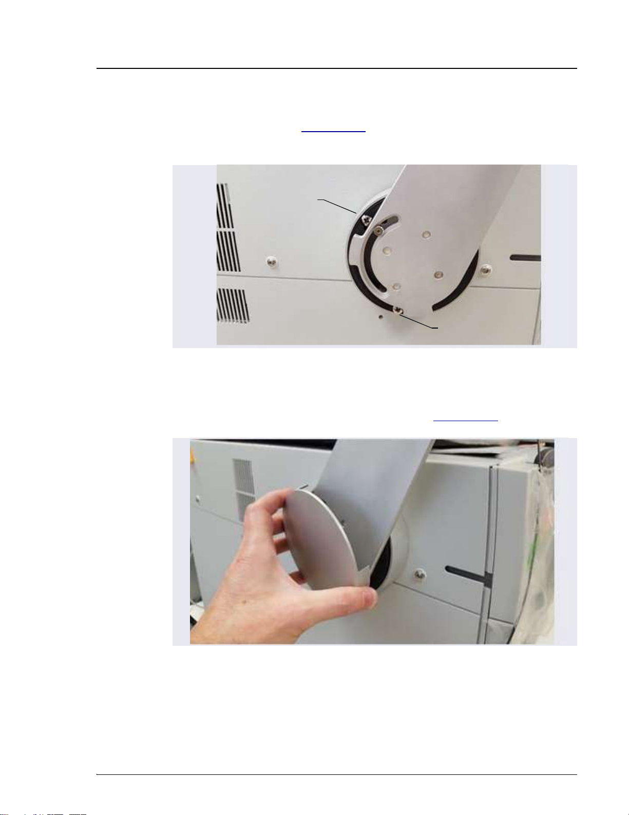
c. Use a 3 mm socket driver to tighten the screws from the front of the
mounting arm (see Figure 3-30). You will need to move the arm to
access all three screws.
2. Reattach the mounting arm cover by aligning it with the arm and moving
it toward the arm until the magnets “grab” (see Figure 3-31).
Figure 3-30. Tightening the Tablet Arm Mounting Screws
Figure 3-31. Reattaching the Cover of the Tablet Mounting Arm/Holder
Mounting Screw
Mounting Screw
Note: Mounting screw
behind arm not visible.

Dionex ICS-6000 Installation Instructions
70 Doc. 22181-97001 02/18
3.9.3 Routing the Tablet Power and Ethernet Cables
This section explains how to perform a partial installation of the tablet power
cable and (if required) the Ethernet cable. The connections will be completed
later in the network installation procedure.
1. Connect the tablet power cable (with the round power connector attached)
to the power port on the tablet.
NOTE The tablet is shipped with an AC power cable with a
U.S. NEMA plug. You are responsible for obtaining a
locally sourced plug adapter.
NOTE If a wireless tablet connection will be used, the Ether-
net cable and network adapter are not needed. The
power adapter for the tablet still must reach the tablet
in any chosen tablet arm orientation.
2. Assemble the cable(s) required to connect the tablet USB port to the
network adapter (see Figure 3-32). The parts are provided in the Tablet
Connectivity Kit (P/N 22181-62017).
a. Connect the 2 m (7 ft) Ethernet cable (P/N 00302-99-00129) to the
USB network adapter (P/N 00302-99-00131).
b. If the Ethernet cable is not long enough, connect the USB cable
(male-to-female) (P/N 00302-99-00130) to the adapter.
3 • System Setup
Doc. 22181-97001 02/18 71
NOTE Set the rest of the kit contents aside for use later.
3. Working from the mounting arm backward, route the tablet power and
Ethernet cables from the tablet holder.
4. Check that the power cable can reach the tablet in any desired orientation,
and then secure the power cable with the spiral cable wraps. If the setup
includes an Ethernet cable, it should be routed similarly.
5. Route the network connector (a USB cable that is either attached to the
network adapter or part of the network adapter) as follows (see
Figure 3-33):
a. Route the cable from the top of the tablet holder downward (leaving
about 254 mm (10 in) of cable beyond the top of the tablet holder),
over the arm of the tablet holder, and toward the DC.
b. Secure the cable with the spiral wraps on the upper and lower sections
of the tablet holder arm.
6. Route the tablet power cable as follows (see Figure 3-33):
a. Route the power cable from the top of the tablet holder downward
(leaving about 254 mm (10 in) of cable beyond the top of the tablet
holder), over the arm of the tablet holder, and toward the DC.
Figure 3-32. Tablet Cable Options
3
1
2
4
5
USB-to-Network Adapter
Ethernet Cable
1
2
3
4
5
Ethernet Cable Ethernet Cable
USB-to-Network Adapter

Dionex ICS-6000 Installation Instructions
72 Doc. 22181-97001 02/18
b. Secure the cable with the spiral wraps on the upper and lower sections
of the tablet holder arm.
Figure 3-33. Tablet Power Cable Setup
USB Network
Connector
Power
Cable
Spiral Wrap
Power
Cable
Routing
3 • System Setup
Doc. 22181-97001 02/18 73
7. Route both the Ethernet and tablet power cables through the tablet arm
cable guide (see Figure 3-34) and back toward the tablet holder.
8. Route the cable from the cable guide, down and under the tablet arm, and
toward the rear of the DC.
9. Use the wiring duct (P/N 22181-98020) provided in the Tablet
Arm/Holder Kit (P/N 22181-62016) to organize the cable run across the
side of the DC (see Figure 3-35):
a. Slide the plastic cover off the wiring duct (or flex the duct).
Figure 3-34. Mounting Arm Cable Guide
Arm (inside
view)
Cable Guide Channel
Cable Guide
Channel
Dionex ICS-6000 Installation Instructions
74 Doc. 22181-97001 02/18
b. Remove the paper backing from the adhesive strip and press the base
of the wiring duct firmly onto the side of the DC. Route the cables
through the duct cover and attach it to the base (see Figure 3-35).
3.9.4 Positioning the Tablet
1. Decide whether to locate the tablet in front of the DC or to the left of the
module.
2. Pull the tablet holder release lever (see Figure 3-36) toward yourself and
swivel the holder to move the tablet to the preferred location.
Figure 3-35. Tablet Wiring Duct Attached to the DC
Figure 3-36. Tablet Connection and Viewing Adjustment
Swivel tablet holder to
preferred location
Tablet Holder
Release Lever
3 • System Setup
Doc. 22181-97001 02/18 75
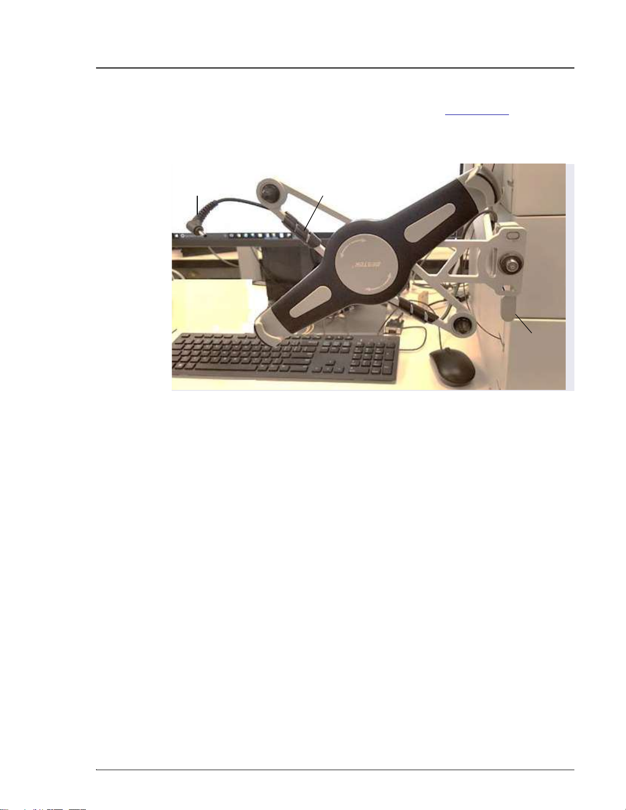
3. You can now attach the tablet to the tablet holder. Figure 3-37 shows an
example installation. If the setup includes an Ethernet cable, the routing
for the cable would be the same as the power cable in the photo.
Figure 3-37. Tablet Connections and Viewing Adjustment
Tablet Power Spiral Wrap
Release
Lever
DC

Dionex ICS-6000 Installation Instructions
76 Doc. 22181-97001 02/18
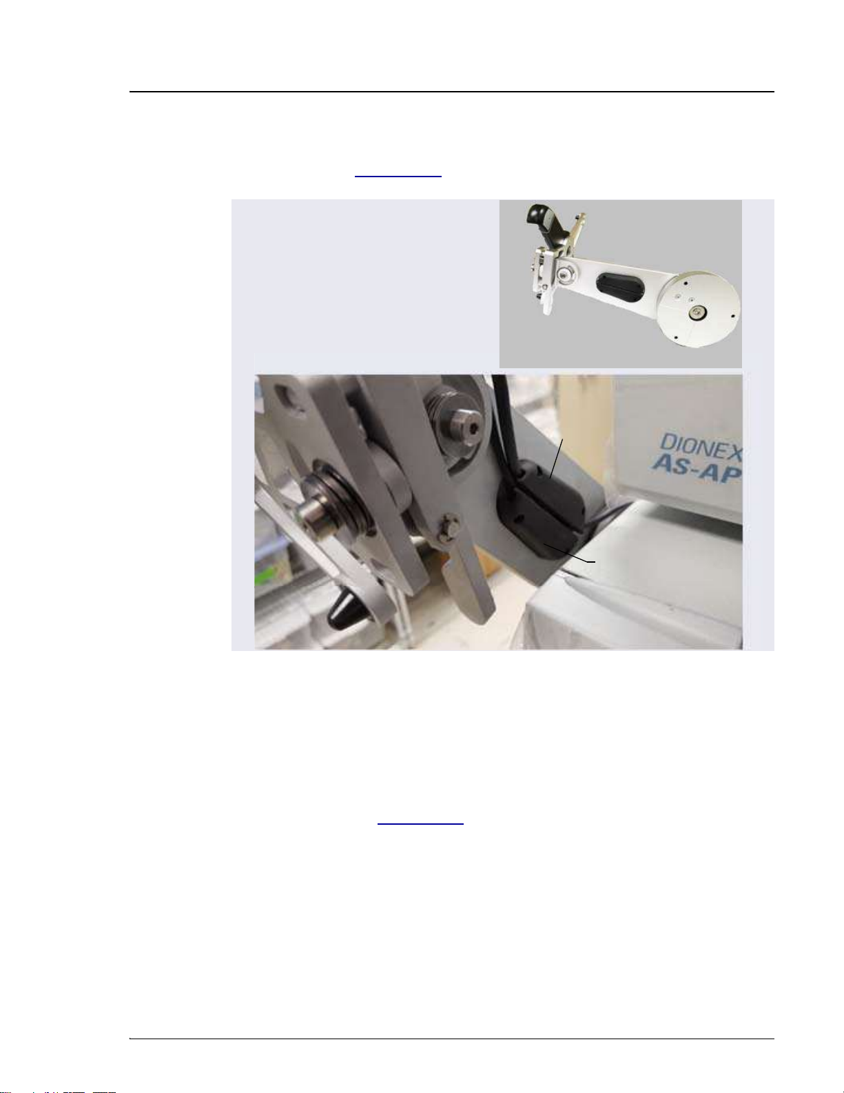
4. Place the lower-left corner of the tablet into the tablet arm/holder (see
Figure 3-38). Pull up the upper-right corner of the tablet and release it to
hold the tablet in place.
5. Adjust the cables to allow enough slack for all the tilt and rotation
positions.
6. While holding down the release lever, use the two hex screws on the
tablet holder to adjust the tablet until it is level (see Figure 3-40).
•When the tablet is to the left of the DC, turning the top screw
counterclockwise loosens the tablet and rotates it in the clockwise
direction.
•When the tablet is in front of the DC, turning the bottom screw
clockwise tightens the tablet and rotates it in the counterclockwise
direction.
7. When you finish, release the lever to lock the tablet into place.
Figure 3-38. Inserting the Tablet into the Holder
Tablet Corner Holder
Tablet Corner Holder

3 • System Setup
Doc. 22181-97001 02/18 77
3.10 Installing a Network for Tablet Access
Configuration options for networking of the Chromeleon instrument PC (IPC)
and the tablet include:
•Ethernet (cabled) connection to IPC (see Section 3.10.2) and Ethernet
(cabled) connection to tablet (see Section 3.10.3)
•Ethernet (cabled) connection from IPC to router (see Section 3.10.2) and
wireless connection from router to tablet (see Section 3.10.4)
•Installations that include a local area network (LAN) in addition to the
IPC and tablet may be possible, but are outside the scope of this manual.
For assistance, contact your network system administrator.
Notes on Network Configurations
•Before selecting a network configuration, verify that corporate IT policy
does not prohibit wireless connections.
•The Tablet Connectivity Kit (P/N 22181-62017) provides a router that is
compatible with Ethernet and wireless connections, cables, and other
parts required for communication (see Section 3.10.1).
•The adapter provided in the Tablet Connectivity Kit does not provide
wireless capability. The adapter changes the connector from Ethernet to
USB; this enables a connection to a USB port if a LAN port is not
available.
PC and Tablet Communication Test
Test network communication at the following times:
•After completing installation of the router, tablet, and IPC.
•Whenever you want to verify that the network is working and that the
tablet and IPC are on the same network.
•Whenever a communication error is suspected.
1. On the tablet desktop, tap the Windows start bar.
NOTE If the tablet was not purchased from Thermo Fisher
Scientific, you must install the ICS-6000 App (see
Section 3.11.1) before testing communication.

Dionex ICS-6000 Installation Instructions
78 Doc. 22181-97001 02/18
2. Tap the search bar and enter “CMD.” A command prompt window is
displayed.
3. Type “ping 192.168.0.1.” This command pings the PC. If the test is
successful, a response appears on the screen showing the number of
packets successfully transferred.
4. To check tablet IP repeat the previous step; this time, use the PC CMD
prompt to ping the tablet IP address (192.168.0.1).
3 • System Setup
Doc. 22181-97001 02/18 79
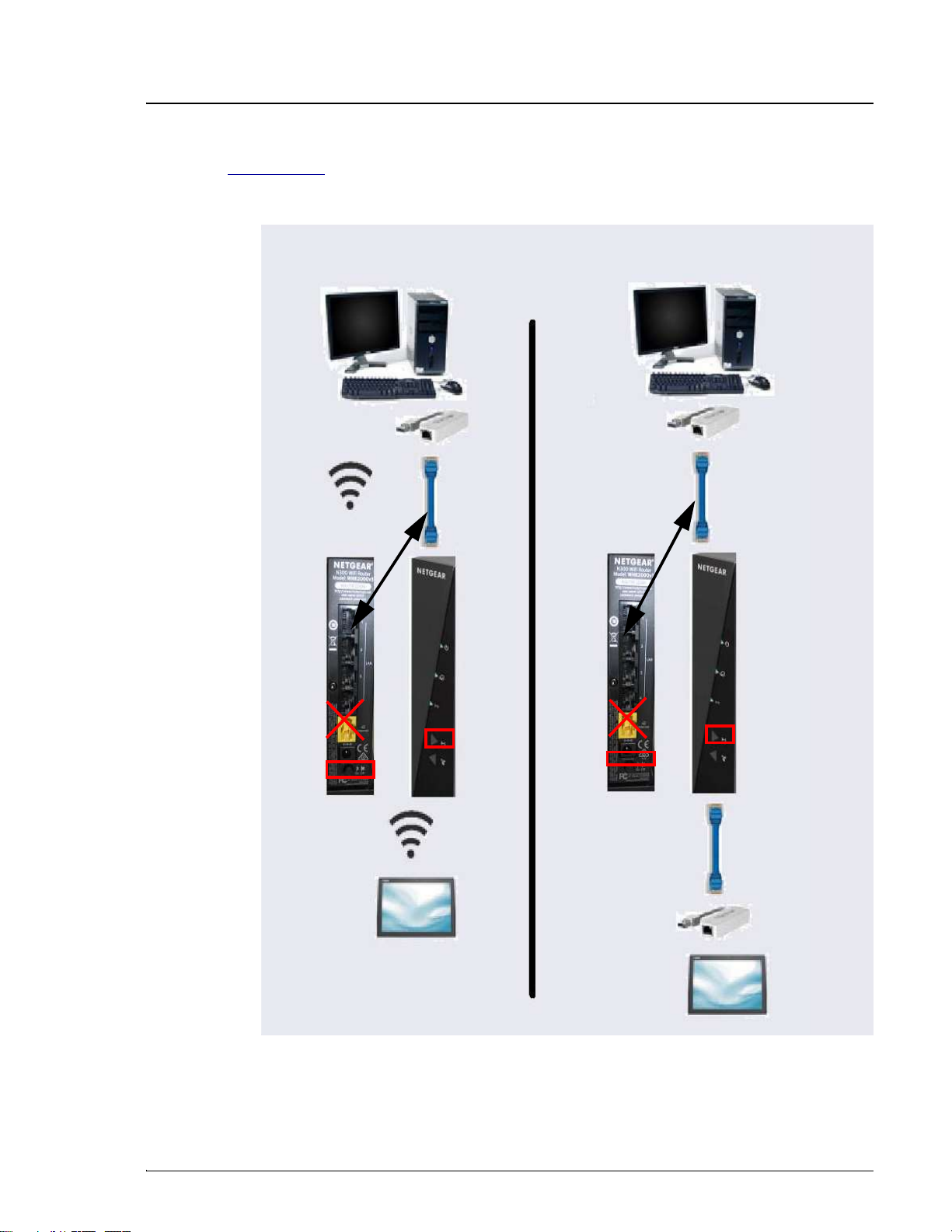
Figure 3-39 provides an overview of connections for both the wireless and
Ethernet networks.
Figure 3-39. Network Connections: Tablet to IPC
Wireless Ethernet
IPC
IPC
USB-to-LAN
Adapter
Ethernet Ethernet
USB-to-LAN
Adapter
Wireless
Router
On/Off
Button
Router
Back Router
Face
Wireless
On/Off
Button
Ethernet
Tablet
Tablet
Wireless
Router
Face
Router
Back
Adapter to USB
Router
On/Off
Button
Wireless
On/Off
Button
Dionex ICS-6000 Installation Instructions
80 Doc. 22181-97001 02/18
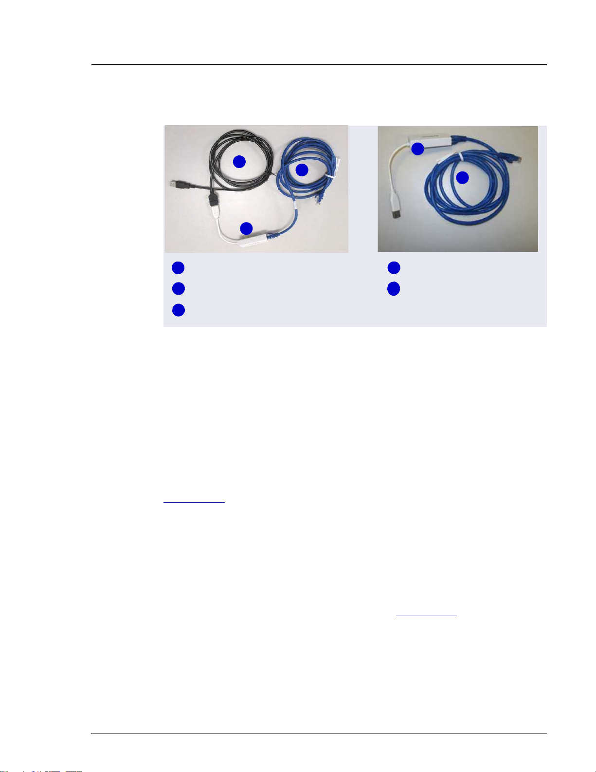
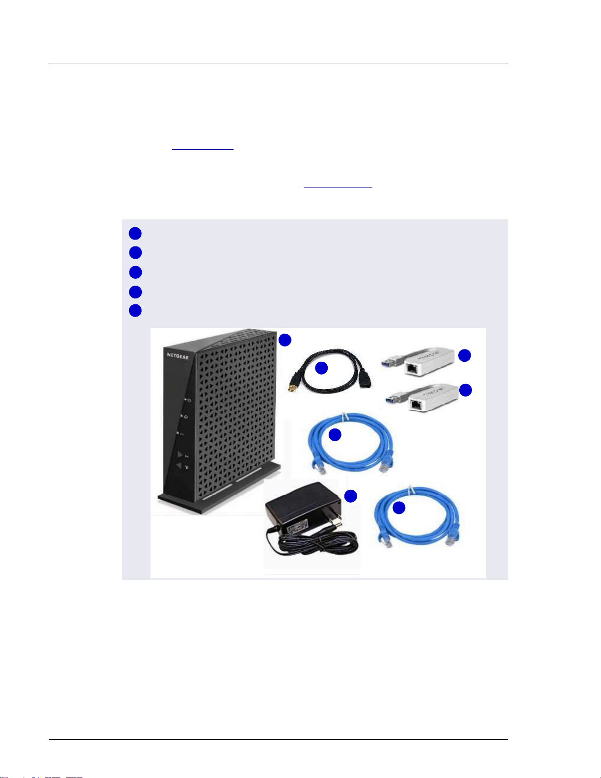
Unpacking the Tablet Connectivity Kit
Unpack the Tablet Connectivity Kit (P/N 22181-62017) and verify the kit
contents (see Figure 3-40).
Reminder: The following items may have been removed from the kit in order
to install the tablet arm and tablet (see Section 3.9.3): one of the two network
USB-to-Ethernet adapters, one of the two Ethernet cables, and the USB cable.
Figure 3-40. Tablet Connectivity Kit Items Unpacked
1
2
3
4
1
5
4
3
4
2
3
5
Wireless Router (P/N 00825-01-00269)
USB-to-Network Adapter (2) (P/N 00302-99-00131)
Ethernet Cable (2) (P/N 00302-99-00129)
USB Cable (Male-to-Female) (P/N 00302-99-00130)
Power Adapter (P/N 00825-01-00269)

3 • System Setup
Doc. 22181-97001 02/18 81
3.10.1 Installing the Router
The router should be installed as close as possible to the DC and IPC because
of the limited Ethernet cable length and wireless broadcast range.
1. Unpack the router (P/N 00825-01-00269) and the router power adapter
(P/N 00825-01-00269).
NOTE The router is shipped with an AC power cable with a
U.S. NEMA plug. You are responsible for obtaining a
locally sourced plug adapter.
2. Each router is assigned a unique network SSID (service set identifier) and
password at the factory. The SSID and password are printed on a label on
the base of the router. Write down this information before proceeding.
3. Connect the outlet prongs of the router power adapter to an electrical
outlet near the Dionex ICS-6000 to which the tablet is attached. If the
tablet arm is not attached, see Section 3.9.2.
4. Attach the connector end of the power adapter to the router.
NOTE If the electrical service is not 120 V 60 Hz, an AC plug
adapter (not provided with the system) is required to
plug in the router power adapter.
5. Press the ON/OFF button on the rear of the router (near the bottom) to
turn on the power.
6. Check the status of the wireless on light on the router (see Figure 3-41).
The light should be green for operation in wireless mode, and red
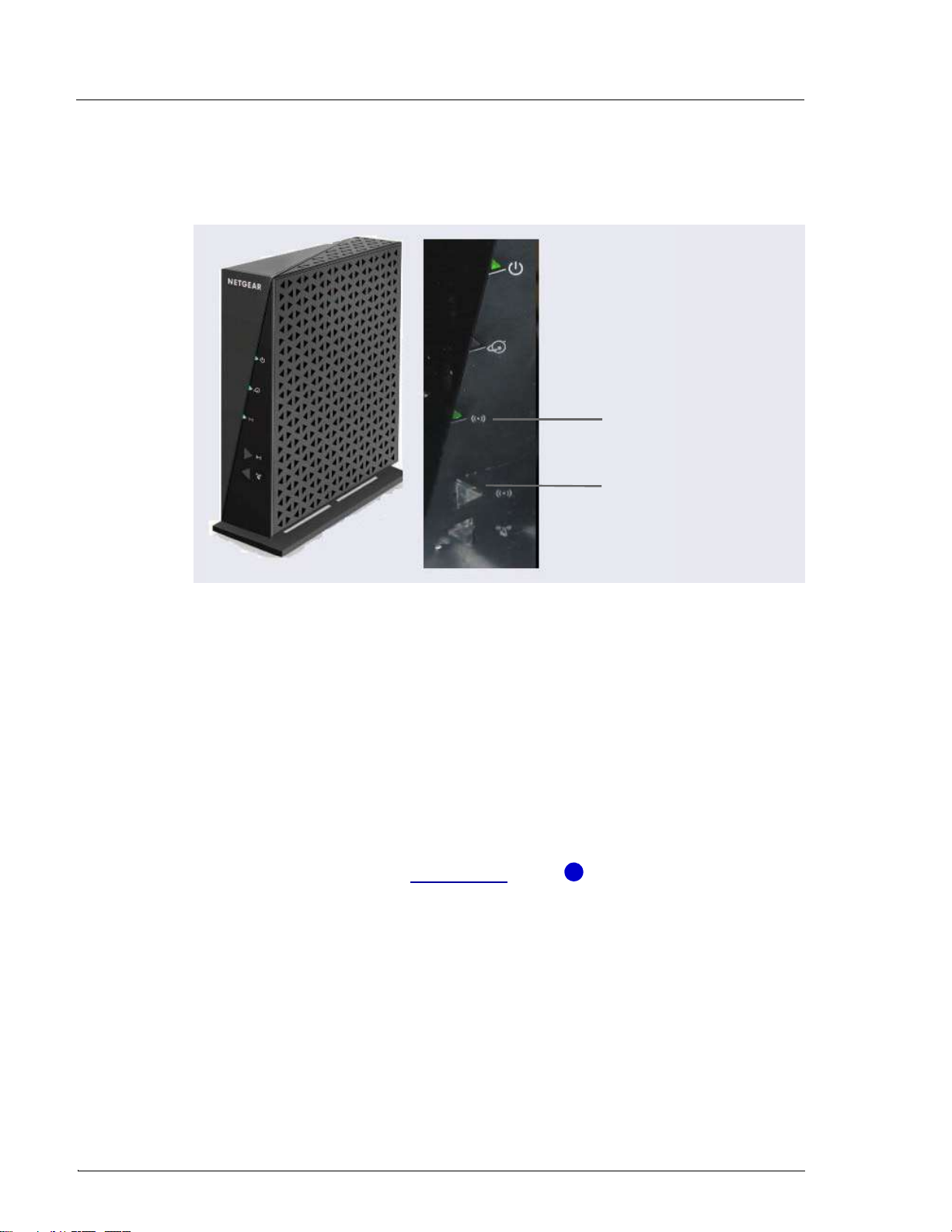
Dionex ICS-6000 Installation Instructions
82 Doc. 22181-97001 02/18
otherwise. If necessary, push the wireless on/off button to change the
mode.
3.10.2 Installing an Ethernet Instrument PC
IPC to Router Connection
This section contains setup instructions for an IPC connected via Ethernet. An
Ethernet connection is required if the IPC does not have wireless connectivity
of if IT policy prohibits wireless connections.
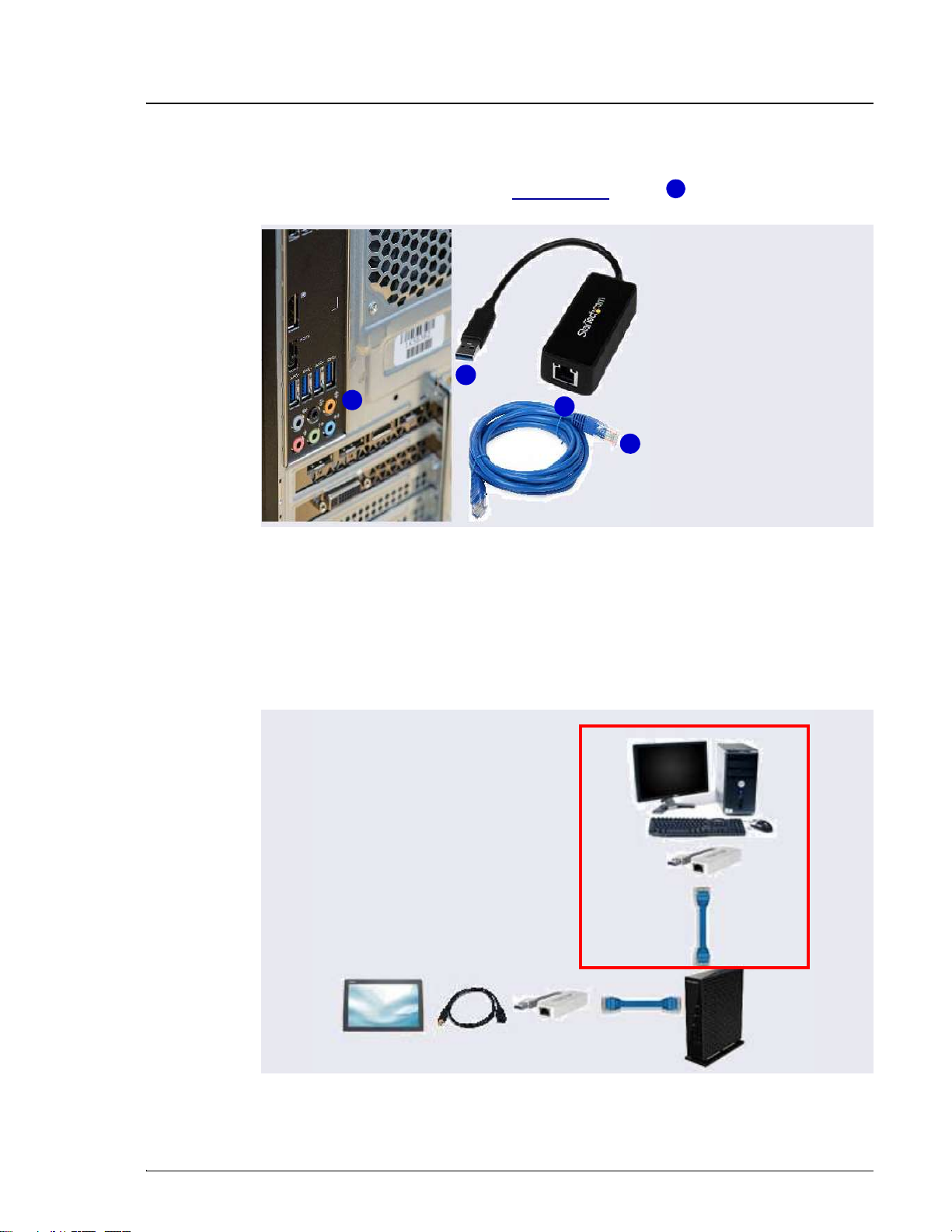
1. If an Ethernet port is not available on the IPC, attach the cable connector
on the USB-to-Ethernet adapter (P/N 00302-99-00131) in the kit to a
USB port on the IPC (see Figure 3-43, item ).
Figure 3-41. Wireless Router On/Off Button and Status Light
Wireless On Light
Wireless On/Off
Button
1
3 • System Setup
Doc. 22181-97001 02/18 83
2. Connect an Ethernet cable (P/N 00302-99-00129) to the USB port on the
USB-to-Ethernet adapter (see Figure 3-43, item ).
3. Connect the other end of the Ethernet cable (P/N 00302-99-00129) to any
available LAN port on the router.
NOTE Do not connect the cable to the yellow Internet port.
Figure 3-42. Ethernet USB-to-LAN Connection
Figure 3-43. Cabling IPC to Router to Tablet
2
1
1
2
2
Ethernet Cable
Tablet
Ethernet
Cable
Router
IPC
USB
Adapter
Optional
USB
Adapter
Optional USB
Extension

Dionex ICS-6000 Installation Instructions
84 Doc. 22181-97001 02/18
3.10.3 Installing an Ethernet Tablet
The hardware installation allows the tablet to send commands through the
router to the IPC. The commands are carried out when they are received from
the router.
1. An Ethernet cable (P/N 00302-99-00129) was routed to the rear of the DC
when the tablet was cabled for the Ethernet connection (see
Section 3.9.4). Connect the free end of the Ethernet cable to any LAN
port on the rear of the router (P/N 00302-99-00131).
NOTE Do not connect the cable to the yellow Internet port.
2. The tablet may already be installed in the tablet holder; if not, place it in
the tablet holder.
3. Connect the Ethernet cable to the tablet, if it is not already connected.
Because the tablet supplied in the Thermo Fisher Scientific tablet kit does
not have a LAN port, the Ethernet connection uses one of the USB-to-
Ethernet adapters provided in the Tablet Connectivity Kit to connect to
the tablet USB port (see Figure 3-44). If necessary, use the USB extension
cable (P/N 00302-99-00130) provided in the Tablet Connectivity Kit
between the adapter and the tablet.
Table of contents


