Neurosoft Neuro-Audio User manual

Technical Manual
Neuro-Audio
Digital System for Auditory EP, OAE
and Screening PTA
TM032.02.003.002
(30.06.2020)

Neurosoft © 2020
5, Voronin str., Ivanovo, 153032, Russia
P.O. Box 10, Ivanovo, 153000, Russia
Phone: +7 (4932) 95-99-99; + 7 (4932) 24-04-34 Fax: +7 (4932) 24-04-35
E-mail: info@neurosoft.com Internet: www.neurosoft.com

3
Contents
Introduction...............................................................................................................4
Abbreviations............................................................................................................5
Intended Use .............................................................................................................6
Contraindications ..................................................................................................... 6
Side Effects............................................................................................................... 6
Safety Measures........................................................................................................7
1. Description.........................................................................................................8
1.1. Product Description ...................................................................................... 8
1.2. Principle of Operation ...................................................................................9
1.3. Connectors and Indicators..........................................................................10
1.4. Labeling......................................................................................................13
2. Preparing the Product for Use........................................................................15
2.1. Requirements to Personnel.........................................................................15
2.2. System Placement......................................................................................15
2.3. Reducing Electrical Noise...........................................................................16
2.4. Unpacking and Checking Delivery Set........................................................18
2.5. Assembly and Connection to Computer......................................................19
3. Proper Use .......................................................................................................21
3.1. Setting-Up Procedures................................................................................ 21
3.2. Performing Tests ........................................................................................22
3.3. Troubleshooting..........................................................................................23
3.4. Actions in Emergency.................................................................................25
4. Maintenance.....................................................................................................25
4.1. General Requirements................................................................................25
4.2. User Maintenance....................................................................................... 26
4.3. Periodic Maintenance.................................................................................26
4.3.1. Checking of OAE Channel with Test Cavity........................................26
4.3.2. Checking of OAE Probe .....................................................................28
4.3.3. Calibration of Stimulus Intensity within Free Field...............................31
4.4. Disinfection.................................................................................................33
4.5. Lifetime.......................................................................................................34
5. Current Repair ................................................................................................. 34
5.1. General Requirements................................................................................34
6. Disposal ...........................................................................................................35
7. Acceptance, Delivery Set and Package Data................................................. 35
8. Warranty........................................................................................................... 36
9. Reclamation.....................................................................................................37
Annex 1. Main Specifications.................................................................................38
Annex 2. Delivery Set..............................................................................................42
Annex 3. Electromagnetic Emission and Immunity..............................................47
Annex 4. Trig In/Out................................................................................................ 51

Neuro-Audio (Technical Manual)
4
Introduction
This technical manual is a combined document describing the operation and servicing
of Neuro-Audio digital system for auditory EP, OAE and screening PTA (hereinafter
referred to as “the system”).
The document certifies the technical parameters of the system, which are guaranteed
by the manufacturer.
Do not start working with the system before you have read this manual!
You can send your responses and recommendations at the following address:
P.O. Box 10, Ivanovo, 153000, Russia
or by e-mail:
You can find additional information on Neurosoft products on our website:
www.neurosoft.com
or contact us by phone:
+7 (4932) 59-21-12 (Service Сenter)
+7 (4932) 95-99-99
+7 (4932) 24-04-34
You can also contact Neuromed Company, Authorized European Representative of
Neurosoft Company (to Mr. Benjamin Scholl) by the following address:
360 avenue du Clapier
ZAСdu Couquiou
84320 Entraigues sur-la-Sorgue
France
Phone: +33 621-304-580
E-mail: inf[email protected]

Abbreviations
5
Abbreviations
ADC — analog-to-digital converter
VЕМP — vestibular evoked myogenic potential
AEP — long-latency evoked potential
TEOAE — transient evoked otoacoustic emission
ABR — auditory brainstem response
MC — microcontroller
OAE — otoacoustic emission
DPOAE — distortion product otoacoustic emission
PC — personal computer
DSP — digital signal processor
AEP — auditory evoked potential
SOAE — spontaneous otoаcoustic emission
MLAEP — middle-latency auditory evoked potential
ASSR — auditory steady-state response
EcochG — electrocochleography/electrocochleogram

Neuro-Audio (Technical Manual)
6
Intended Use
The Neuro-Audio system is intended for use in electrophysiological and audiologic
evaluation of hearing and vestibular function as an aid in detecting hearing loss and
diagnosing hearing and vestibular related disorders. It can be used for screening and
diagnostic applications. It allows recording auditory brainstem response (ABR) and
other auditory evoked potentials (AEP), otoacoustic emissions (OAE) and screening
pure tone audiometry (PTA).
Neuro-Audio bone conduction amplifier unit is intended to record bone conduction
VEMPs. The target population for Neuro-Audio includes all ages.
The Neuro-Audio system must be used by trained personnel only, such
as audiologists, ENT surgeons, hearing healthcare professionals, trained technicians
or personnel with a similar level of education in a hospital, clinic, healthcare facility
or other appropriate professional healthcare setting. The device should not be used
without the necessary knowledge and training to understand its use and how results
should be interpreted.
Contraindications
The Neuro-Audio system must not be used:
·if patient suffers from external otitis;
·if the insertion of the ear probe (or application of any other transducer) in the ear
canal makes patient feel pain.
The Neuro-Audio system can be used, but with care:
·if patient has allergic or infectious skin diseases at the electrode or transducer
application sites.
Side Effects
There are no known undesirable side effects for the Neuro-Audio system.

Safety Measures
7
Safety Measures
To provide safety measures and exclude the possibility of electric trauma
of medical staff or patients, the medical staff is PROHIBITED to:
·use the system which mounting and setting was done improperly, without following
this technical manual;
·connect the system and surgical HF equipment to the patient simultaneously (it can
cause system damage or patient’s flash-burns in places of electrode placement);
·plug in any products not included into the delivery set, to the electrode connectors;
·eliminate faults by opening of the components included into the delivery set;
·conduct tests when the electronic unit box, computer or other devices comprising
the system are opened;
·connect patient electrodes to protective ground or other conducting surfaces.

Neuro-Audio (Technical Manual)
8
1. Description
1.1. Product Description
The Neuro-Audio is a multifunctional screening and/or diagnostic system that
interfaces with the Neuro-Audio.NET audiologic software on a PC. It is a device with
built-in 2-channel amplifier for evoked potentials recording, built-in microphone
amplifier for OAE recording and a built-in auditory stimulator. The software is used
to control the device during testing, to analyze, save and retrieve the recorded test
data, to print test reposts.
Depending on the installed software modules and licenses, it supports the following
tests:
‒auditory evoked potentials (ABR, AABR, ECochG, MLR, LLR);
‒otoacoustic emission (TEOAE, DPOAE, SOAE);
‒auditory steady-state response (ASSR, multi-ASSR);
‒cognitive evoked potentials (P300, MMN);
‒vestibular evoked myogenic potentials (VEMP: air and bone conduction);
‒pure tone audiometry (PTA: air, bone conduction and free-field).
There are 4 customized delivery sets of the Neuro-Audio system:
1. Standard delivery set (intended for ABR, AABR, VEMP and otoacoustic emission
tests: TEOAE, DPOAE, SOAE).
2. Neuro-Audio/ABR delivery set (intended only for ABR, AABR tests).
3. Neuro-Audio/OAE delivery set (intended only for otoacoustic emission tests:
TEOAE, DPOAE, SOAE).
4. Neuro-Audio/PTA delivery set (intended only for screening pure tone audiometry).
Description
9
1.2. Principle of Operation
The principle of operation is based on the recording and input of bio-potentials and
other physiological signals to computer and their further processing and analysis.
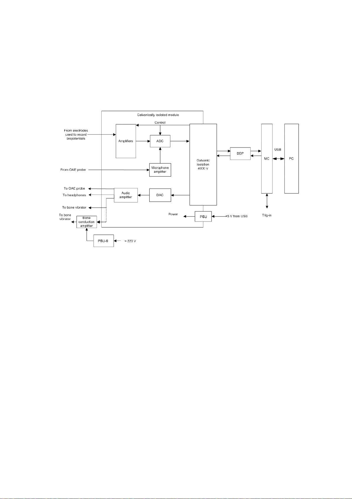
The block diagram of the system is shown in Fig. 1.
Fig. 1. The Neuro-Audio system
Biopotentials from the electrodes are transferred to the amplifiers, where they are
amplified and then digitized by the analog-digital converter (ADC) delivered
to the digital signal processor (DSP) via 4000 V galvanic isolation. The DSP controls
the operation of the amplifiers and ADC via 4000 V galvanic isolation.
The unit microcontroller (MC) provides the connection between DSP of the module
and the computer via USB. The DSP generates audio stimulator signal in a digital
form which is converted to the analogous form by the digital-analogue converter
(DAC). Then, the signal is amplified by the audio amplifier and delivered
to the auditory stimulator. If there is a bone conduction amplifier, the signal
is delivered from the audio amplifier output. Then, the amplified signal is delivered
to the bone vibrator. Besides, the unit microcontroller receives trig-in signals and
synchronizes them with the data flow from ADC.
The bone conduction amplifier is powered via mains-operated medical power supply
unit (PSU-9) or built-in batteries.
The galvanically isolated part of the amplifier unit (the amplifier module) is powered
via galvanically isolated DC converter of the power supply unit (PSU).
The digital system operates under control of PC (IBM PC type) with a mouse,
keyboard, laser or jet printer and installed licensed Windows OS. Using PC,

Neuro-Audio (Technical Manual)
10
the received signals are processed, displayed and presented in the different modes
after mathematical analysis. The initial data is stored on the hard disk and the exam
reports are generated and printed.
1.3. Connectors and Indicators
The front and side panels of the electronic unit are shown in Fig. 2, Fig. 3 and Fig. 4.
On the front panel of the electronic unit (Fig. 2) there are the touch-proof and DIN
connectors to attach the electrodes, the impedance button to switch to the Impedance
measurement mode and the LED indicator. The channels are marked with figures
“1” and “2”. The on/off indicator glows yellow when the unit is connected to PC and
it glows green during the signal recording.
The impedance indicators glow in the impedance measurement mode. You can switch
to this mode using the Neuro-Audio.NET program settings (see user manual)
or the Impedance measurement button. The colour of indicators means the quality
of the electrode placement. The green colour means the quality is high, yellow colour
– the quality is average and red colour – the quality is poor. The colours are specified
in the software settings.
Fig. 2. Front panel
Designations shown in Fig. 2:
1 — impedance indicators;
2 — “Impedance” button;
Description
11
3 — ON/OFF indicator;
4 — Touch-proof connectors;
5 — DIN connectors.
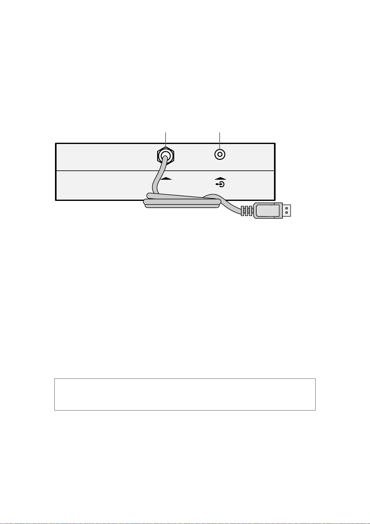
On the top side panel of the electronic unit (Fig. 3) there is a trigger socket (trig-in/trig-
out) to attach stimulators of third-party manufacturers and the USB cable for
connection to PC.
1 2
PC
Fig. 3. Top panel
Designations shown in Fig. 3:
1 — USB cable.
2 — Trigger socket (trig in/trig out).
On the bottom side panel (Fig. 4) there are the connectors to attach the headphones,
bone vibrator and OAE probe.
There are two types of connectors to attach the headphones: 3.5 stereo and
6.3 mono. Depending on the plug, they can be inserted in this or that connector. If you
use the headphones with 6.3 mono plug, pay attention to the order of connection.
The left headphone must be plugged into the connector marked as “L”, the right one
must be plugged into the connector marked as “R”.
Do not attach the headphones to the 3.5 stereo and 6.3 mono connectors
simultaneously. It leads to incorrect stimulus volume in the headphones.
There are two types of connectors to attach OAE probe: mini DIN 6 manufactured
by Neurosoft (Russia) and mini DIN 8 manufactured by Etymotic Research (USA).

Neuro-Audio (Technical Manual)
12
Fig. 4. Bottom panel
Designations shown in Fig. 4:
1 — connectors for headphones;
2 — connector for OAE probe (Neurosoft);
3 — connector for OAE probe (Etymotic Research);
4 — connector for bone vibrator.
The front and back panels of the bone conduction amplifier are shown in Fig. 5 and
Fig. 6. The description of indicator colors is shown in Table 1.
Fig. 5. Front panel of bone conduction amplifier
Connector for Neuro-Audio electronic unit
Charge indicator
Ready light
Connector for bone vibrator Connector for temperature sensor

Description
13
Fig. 6. Back panel of bone conduction amplifier
Table 1. The description of colors of bone conduction amplifier indicators
Color of indicator
Description
Ready indicator: green
Charge indicator: green The unit is on and ready for operation (stimulation).
Ready indicator: no illumination
Charge indicator: green Discharged battery. Charging from mains is required.
Charge indicator: yellow or orange The built-in rechargeable battery is charging from
mains (it usually takes 6-7 hours for complete
charge).
Charge indicator: green (flashing) Battery is fully charged.
Ready indicator: red The bone vibrator overheat protection actuated.
1.4. Labeling
The example of the label for the system is shown in Fig. 7.
Fig. 7. The example of the label for the system
Interpretation of symbols on the label:
– attention: consult operational documentation.
-
work parts of BF type according to EN 60601-1.
-
mark of conformance to 93/42/EEC “Concerning Medical Devices”
directive
Connector for
PSU
-
9
power
supply unit
On/off button

Neuro-Audio (Technical Manual)
14
-
mark of conformance to 2012/19/EC “On waste electrical and electronic
equipment (WEEE)” directive.
– number according to catalogue by ISO 15223-1.
-
serial number by ISO 15223-1.
-
date of manufacture by ISO 15223-1.
-
manufacturer’s name and address ISO 15223-1.
– ingress protection marking by EN 60529.
The equipment is identified with the GS1-128 barcode that includes the GTIN code
and the serial number (Fig. 8).
Fig. 8. The GS1-128 barcode
1 – identification key: GTIN,
2 – start digit,
3 – company number,
4 – article reference,
5 – check digit,
6 – serial number identifier,
7 – serial number.
GTIN – global trade item number can be used by a company to uniquely identify all
of its trade items. GS1 defines trade items as products or services that are priced,
ordered or invoiced at any point in the supply chain.
To ensure the automatic data reading the GS1-128 code is integrated to the barcode
in DataMatrix format (Fig. 9).

Preparing the Product for Use
15
Fig. 9. DataMatrix barcode
Data Matrix is a two-dimensional matrix barcode, consisting of black and white “cells”
or modules of different brightness arranged in either a square or rectangular pattern.
The DataMatrix barcode is described in ISO/IEC 16022:2006 standard.
To decode the data on device, DataMatrix barcode can be read quickly by a barcode
reader or by the smartphone camera as a two-dimensional image.
2. Preparing the Product for Use
2.1. Requirements to Personnel
The mounting and setting of the system should be carried out by the person
empowered by the manufacturer or technical personnel of the medical institution
where the system is to be used. Remember, that accurate mounting of the system
defines its safety and operation quality. Further, the important requirements
for the mounting and setting of the system will be marked by bold and italic fonts.
2.2. System Placement
Before mounting and setting the digital system, select a place for it taking into
consideration the power wiring and protective ground in the room and follow
the requirements and recommendations listed below.
Requirements concerning the room selection and placement of equipment:
·The recommended distance from the electronic unit to the short-wave or microwave
therapeutic equipment is not less than 5 meters.
·The patient environment (within 1.5 meters) should contain only
the electronic unit being the medical device with the required safety level.
The fact is that the safety level of the computer equipment is insufficient
for the use in the patient environment. Hence, a patient must not contact with
the metal parts of computer equipment cases and the personnel must
not touch simultaneously these parts and patient body. If the computer
equipment used in the system corresponds to EN 60601-1 or is connected via
the isolation transformer corresponding to EN 60601-1, and the isolation from
the computer network is provided via the special isolation device
corresponding to EN 60601-1, then it is not obligatory to fulfill this
requirement.

Neuro-Audio (Technical Manual)
16
·Place the electronic unit on the maximum possible distance from power cables,
switchboards, and different powerful electrical devices which can emit
electromagnetic fields of mains frequency.
Requirements to mains:
·The system should be supplied from 230 V mains equipped with TN-S or TN-C-S
ground system (according to IEC 60364-1).
·To avoid the risk of electric shock, this equipment must only be connected
to supply mains with protective earth.
·Before setting of the digital system, the quality of standard tripolar sockets
and the integrity of protective ground circuit must be checked
by the electrician. For more details see section 2.3 “Reducing Electrical
Noise”.
·In case the system components are connected to several tripolar sockets,
make sure they are grounded to one and the same protective ground circuit.
Otherwise, there is a danger of compensating current leakage (several tens
of amperes) through the system connecting cables that leads
to the equipment break-down.
2.3. Reducing Electrical Noise
There are some factors that may impact ABR test results. They are the electrodes
placement and its impedance, patient’s condition, ambient noise. However,
the electrical interference is the most important factor that can worsen the result
greatly. The information concerning the electrical interference reduction is given in this
section.
Grounding is crucial for the good ABR recording and safe operation.
The power cord contains a ground lead (typically indicated by yellow and green
colours), but often the ground at the test site may not be sufficient.
In such cases follow these recommendations.
Ground the patient bed if it is made of metal.
Turn off all other electrical equipment not used in the room, especially
the sources with neon lights.
In some cases, it may be necessary to find another room for testing if there is too
much ambient or electrical noise.
You can also try to move a test site within the room as the patient might be near
the power cord (or a kind of that) hidden in the wall close to the patient and
electrodes.

Preparing the Product for Use
17
Electrical interference may also appear through the ground lead if this is connected
to many computers, autoclaves, instruments using high power etc. In this case
a dedicated ground for the ABR recording site should be established.
Avoid any mixing of cables (for example, USB cables/power cord etc. mixed
up with the electrodes cable used for the EP system).
Sometimes, the ground lead is found inside the wall outlet, but it is not connected
to the ground.
If the ground is not connected or even missing, the ABR recordings will be distorted
greatly.
The Neuro-Audio digital system is connected to the ground lead via a ground contact
of tripolar outlet. If the ground lead is not connected, the digital system will pick
up electrical noise/interference. On the screen it will be displayed as total harmonic
distortion fully overlapping the ABR waveforms.
Some notebooks are not provided with the ground connection to the outlet ground.
If you use such a notebook as a part of the digital system, take special measures
to ensure the notebook ground contact to the outlet ground. To do this, use the power
supply units with the required contact (a tripolar connector for mains lead attachment).
To make sure that there is a connection between the notebook ground and outlet
ground, measure the impedance between the protective ground pin of power supply
unit outlet and ground connector pin attached to notebook. The impedance should not
exceed 0.1 Ω.
Check the ground for proper and correct function of the digital system.
Due to high voltage, only experienced technicians or properly trained staff
must change and check the ground.
To check the ground, follow these recommendations:
1. Use a dedicated ground tester.
2. Compare voltage/impedance from the wall outlet ground lead to a triangle
of earth rods. The resistance must not exceed 8 Ω, and the peak-to-peak
amplitude must not exceed 0.5 V.
3. More simple check is to use a voltage meter and measure the voltage directly
in the wall outlet. Check the following:
3.1. The voltage between the phase (hot) and zero (neutral) sockets must
be stable (230 V for Europe /110 V for US (country specific).

Neuro-Audio (Technical Manual)
18
3.2. The voltage between the phase (hot) and ground sockets must be stable
(230 V for Europe/110 V for US (country specific). It is the same voltage
as in item 3.1 (see above) with a deviation of max 5 V.
If the measured voltage is much less than 230 V Europe/110 V US,
the ground is not connected to true ground. Even though you can see
the lead inside the wall outlet this lead is not connected to the true ground.
3.3. The voltage between zero (neutral) and ground it must be at about 0 V.
If the measured voltage differs much from 0 V, it means that the ground
is not connected to the true ground. Even though you can see the lead
inside the wall outlet this lead is not connected to the true ground.
The ABR equipment must be connected to a proper true ground to provide safe
operation and obtain good ABR recording and correct test results.
To obtain the best ground, a separate ground dedicated to ABR recording site should
be wired and connected directly to the true ground using at least three earth rods.
The best test site for ABR recordings is:
1. The electric magnetic shielded room (it is also soundproof as well).
2. Separate ground only for ABR recording.
Besides, follow these recommendations to exclude other factors except electrical
noise:
1. Turn off the light and other electrical equipment not being used as the patient will
be as antenna and pick up electrical interference.
2. Conduct testing in a soundproof room.
3. Do not let other patients/visitors come in the room as they may disturb the patient
trying to relax.
2.4. Unpacking and Checking Delivery Set
If the box with the digital system was under the conditions of excessive moisture
or low temperature which differs significantly from the working conditions, place
it in the room with normal conditions and leave there for 24 hours.
Unpack the box and take out the components of the digital system. The delivery set
should coincide with the packing list.
The computer equipment packed in separate boxes should be opened according
to the user and technical manuals for these products.

Preparing the Product for Use
19
Check the components of the digital system and make sure that there is no external
damage.
2.5. Assembly and Connection to Computer
If you buy the digital system with the computer, the equipment is delivered with
installed and configured software. If you buy the digital system separately, please,
install the software from the flash drive included in the delivery set.
The software must be installed before the first connection of the digital
system to PC. Read the corresponding section of the user manual before
starting to work.
If the electronic media with the software is not available, please contact
your local dealer. The list of authorized Neurosoft dealers can be found
here: https://neurosoft.com/en/pages/dealers.
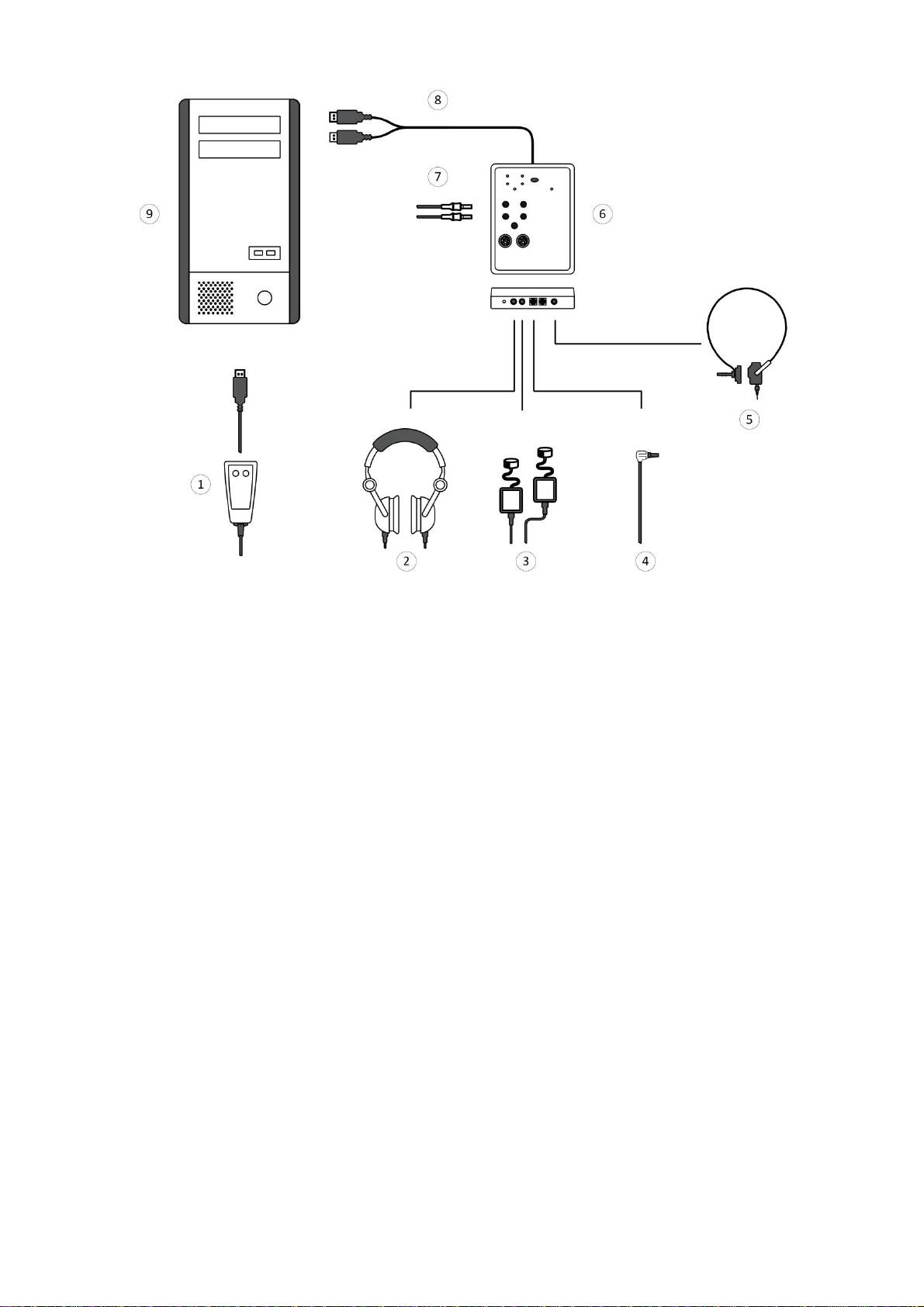
The digital system consists of the electronic unit and can be supplied with the patient
button depending on the delivery set variant (Fig. 10). The electronic unit and patient
button can be connected to PC either directly or using USB hub (not shown
in Fig. 10). Remember, that the USB connector of the electronic unit (with a blue
mark) and the patient button must be attached to the same USB controller of your PC.
It can be done, if:
·the devices are attached to one and the same USB hub;
·the devices are attached to the alongside USB connectors (typically, the connectors
of one controller are located nearby);
·the devices are attached to different USB hubs but connected to one and the same
USB controller.
Do not use the system with the USB hubs not connected to the mains.
The connection to USB connectors on the monitor or keyboard does not
ensure the correct device operation.
Neuro-Audio (Technical Manual)
20
Fig. 10. Connection to PC
Designations shown in Fig. 10:
1 — patient button,
2 — auditory stimulator,
3 — insert earphones,
4 — OAE probe,
5 — bone vibrator,
6 — Neuro-Audio electronic unit,
7 — electrodes,
8 — to USB connector,
9 — PC system unit.
Place the holder to the testing site as near as possible and fix the Neuro-Audio
electronic unit on it. Connect the required equipment (according to Fig. 10).
The electrical units can be connected to PC when the power supply is on or off.
The Neuro-Audio electronic unit is supplied with a cable with two USB connectors.
To ensure the proper operation, attach both connectors to PC.
Table of contents
Other Neurosoft Diagnostic Equipment manuals


