Filtrine QCP Manual

QCP INSTALL]
REV. 03.15.19
Filtrine Mfg. Co. • 15 Kit St. Keene, NH 03431 USA
800-930-3367 • 603-352-5500 • FAX 603-352-0330
WEB www.filtrine.com • EMAIL cool@filtrine.com
FILTRINE IS ISO 9001:2015 CERTIFIED
PRODUCT LINE APPROVED MARK AVAILABLE
MADE IN USA
Please read these instructions completely before installation.
INSTALLATION INSTRUCTIONS
The QCP Quick Connect Panel provides all the diagnostics that
medical equipment manufacturers require.
• Mount the QCP panel in a location where meters can be
read by the medical equipment operators. Consideration
should be given to the routing of chilled liquid line.
• Excessive pipe lengths cause heat gain as well as pressure
reduction. Locate the panel between the chiller and medical
equipment, preferably close to the medical equipment.The
closer the panel is to the medical heat exchanger, the more
useful the temperature readings will be.
• All coolant lines must be insulated to reduce heat gain and
to prevent condensation from forming during high humidity
conditions.
• The piping procedure simply consists of matching QCP
connections to the appropriate points and setting the ball
valves to the desired operation mode. (See Operation
Modes table on page 2.)
• If plumbing line size reduction is being considered, it
must be veried that proper ow and pressure can be
maintained. As a general rule, reducing the pipe size is not
recommended.
• When installation has been completed, put the unit in Full
Bypass Mode. Close the ball valve that feeds the city water
drain while lling the system. If this valve is left open while
the chiller is inoperative and being lled, the uid being
added to the system will run down the drain. Once the chiller
has been started, open this valve.
A list of plumbing/electrical connections to the QCP panel
and where they should be routed:
CITY WATER DRAIN*This connection is piped to a oor
drain or any other suitable water
disposal drain.
TO CHILLER Piped to the RETURN connection
at the chiller.
FROM CHILLER Piped to the chiller DISCHARGE
connection.
CITY WATER SUPPLY*Connect to the municipal water
supply for backup cooling.
FROM EQUIPMENT Piped to the discharge line of the
medical equipment.
SOLENOID COILS*Connect the wires in parallel and
refer to the chiller electrical dia-
gram.
* Optional equipment for QCP-AS
OPERATION
Your QCP will give you years of trouble-free service. Like any
other piece of ne equipment, occasional maintenance may
be required.You will soon discover the exibility designed into
the QCP. In most circumstances, service can be performed on
the unit or chiller without interrupting medical requirements.
There are ve operation modes of the QCP panel summa-
rized below:
1. NORMAL
OPERATION
The standard operating conguration. See
Mode 1 on next page and note location/
settings of valves and ow paths.
2. FULL
BYPASS
This conguration isolates the chiller from
the medical equipment. It can be used when
starting the chiller if the medical equipment
is not yet operational. The chilled water is
simply routed from the chiller discharge
back to the return line. See Mode 2 in chart
on next page and note location/settings of
valves and ow paths.
3. SERVICE
FLOW
METER
In the event the ow meter or other instru-
ments in this path need service, ow can
be routed as shown. See Mode 3 in chart
on next page and note location/settings of
valves and ow paths.
4. SERVICE
FILTER
Filter changes will be required when the
system is initially started and periodically
thereafter. This mode allows uninterrupted
service to the medical equipment while a l-
ter change takes place. See Mode 4 in chart
on next page and note location/settings of
valves and ow paths.
5. CITY
WATER
BACKUP*
This condition will occur if the chiller fails
and actuates solenoids 1 and 2. Notice that
the ow of water is from the city water con-
nection through the medical equipment
and down the drain. IMPORTANT: The city
water pressure must not exceed 80 p.s.i.
The automatic backup will only work if the
system was previously operating in Mode 1
(Normal Mode). See Mode 5 in charton next
page and note location/settings of valves
and ow paths.
* Optional equipment for QCP-AS
Charts on reverse
FILTRINE QCP – QUICK CONNECT PANEL
INSTALLATION, OPERATION AND MAINTENANCE INSTRUCTIONS
QCP INSTALL]
REV. 03.15.19
Filtrine Mfg. Co. • 15 Kit St. Keene, NH 03431 USA
800-930-3367 • 603-352-5500 • FAX 603-352-0330
WEB www.filtrine.com • EMAIL cool@filtrine.com
FILTRINE IS ISO 9001:2015 CERTIFIED
PRODUCT LINE APPROVED MARK AVAILABLE
MADE IN USA
FILTER MAINTENANCE
The lter is a bag type. Using a 50 micron
bag, the pressure drop is less than 5 p.s.i.
when new.The lter should be changed
if the pressure drop across the unit ex-
ceeds 12 p.s.i. A spare lter should be
kept on hand at all times.
Study the flow path of Mode 4 op-
eration in the chart to the right. This
conguration allows the replacement
of the lter element while delivering
uninterrupted flow to the medical
equipment.This will probably be the rst
routine maintenance performed on the
QCP. Since the system is a closed loop,
the coolant will eventually be cleaned
of all contamination and lter changes
will become rare.
If repeated city water operation is
actuated, lter contamination is likely.
The lter element should be changed
when the pressure drop across the unit
is greater than 12 p.s.i.g.
FILTRINE QCP – QUICK CONNECT PANEL
INSTALLATION, OPERATION AND MAINTENANCE INSTRUCTIONS
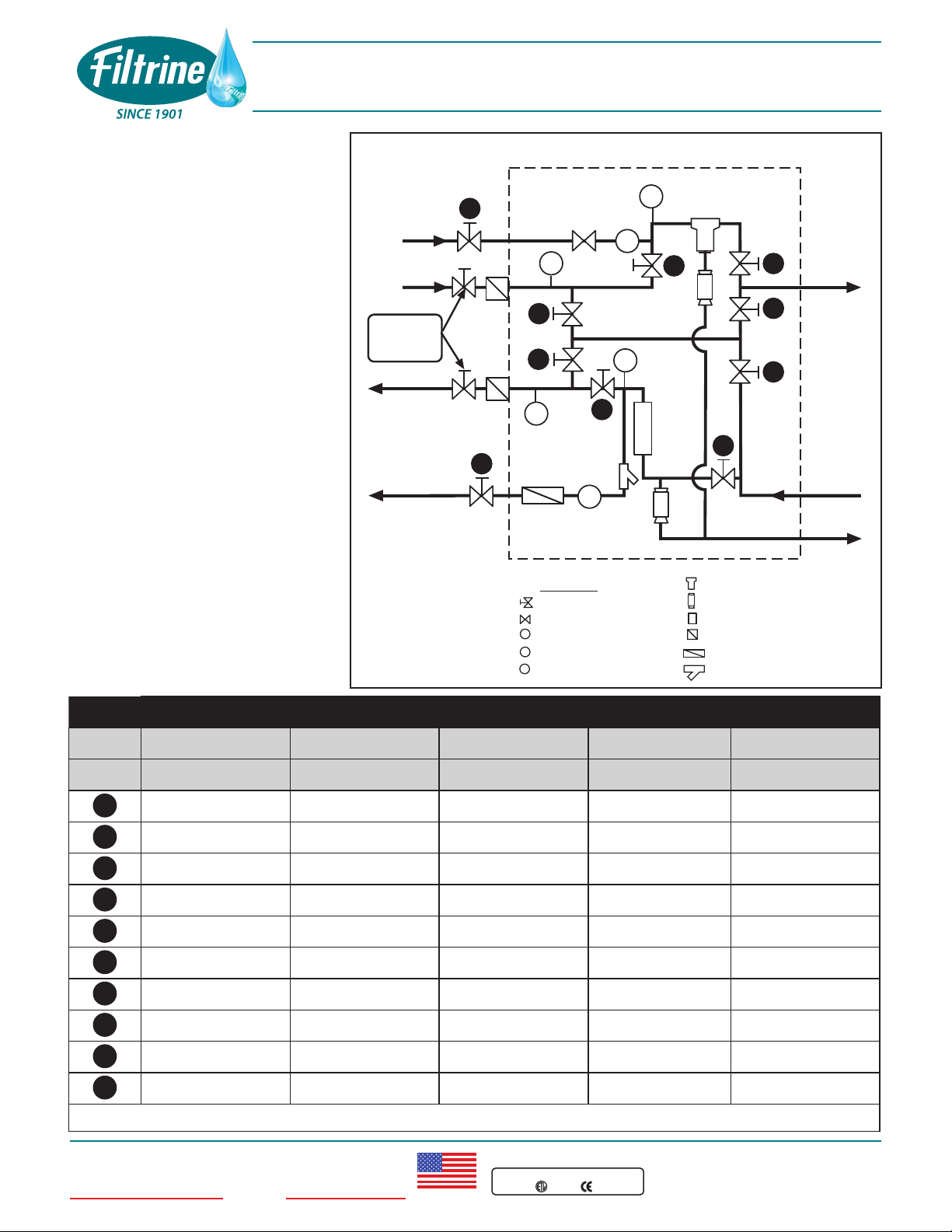
QCP OPERATION MODES: O=OPEN / C=CLOSED
NORMAL FULL BY-PASS SERVICE FLOW METER SERVICE FILTER CITY WATER BACK-UP
*
VALVE 1 2 3 4 5
AO O O C O
BO O O C O
CC C C O C
DC O C O C
EC C O C C
FO O C O O
GC O O C C
HO O C O O
IO C O C O
JO C O O O
*Optional equipment for QCP-AS
T
P
S
M
F
T
P
S
F
S
P
BALL VALVE
BACKFLOW PREV.
SOLENOID
PRESSURE GAUGE
TEMP. GAUGE
CITY
WATER
IN (OPT.)
A
I
B
CD
E
F
G
H
J
QCP PLUMBING SCHEMATIC
T
M
FILTER
1/2" DRAIN VALVE
FLOW METER
CHECK VALV E
IN-LINE CK VALVE
Y- STRAINER
LEGEND
TO
CHILLER
FROM
CHILLER
Provided by
installing
contractor
CITY WATER
DRAIN (OPT)
FROM
EQUIP
TO
DRAIN
TO
EQUIP
This manual suits for next models
1


