Daikin Service Checker TYPE 3.1 User manual

- 0 -
SERVICE CHECKER TYPE 3.1
INSTRUCTION MANUAL
Issued by
Maintenance Sales Dep.
After Sales Service Div.
DAIKIN INDUSTRIES LTD.
201210

- 1 -
Contents
Introduction 2
Outline of the Manual --------------------------------------------------------------------------------- 3
Confirming of packaged items -----------------------------------------------------------------------4
Preparation-------------------------------------------------------------------------------------------------5
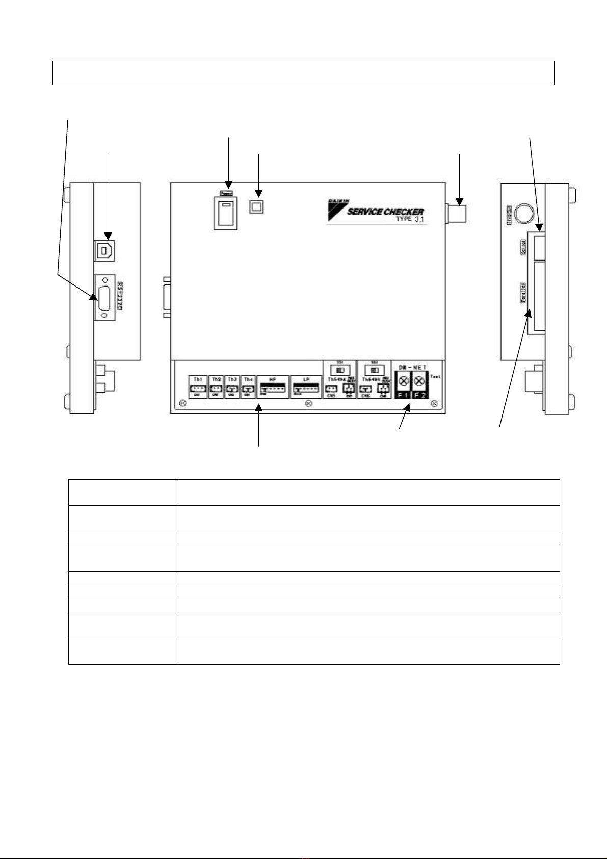
Name of each part --------------------------------------------------------------------------------------6
Chapter 1 Installing of TYPE 3 software 7
1.1 Obtaining Service Checker TYPE3 software ---------------------------------------------- 7
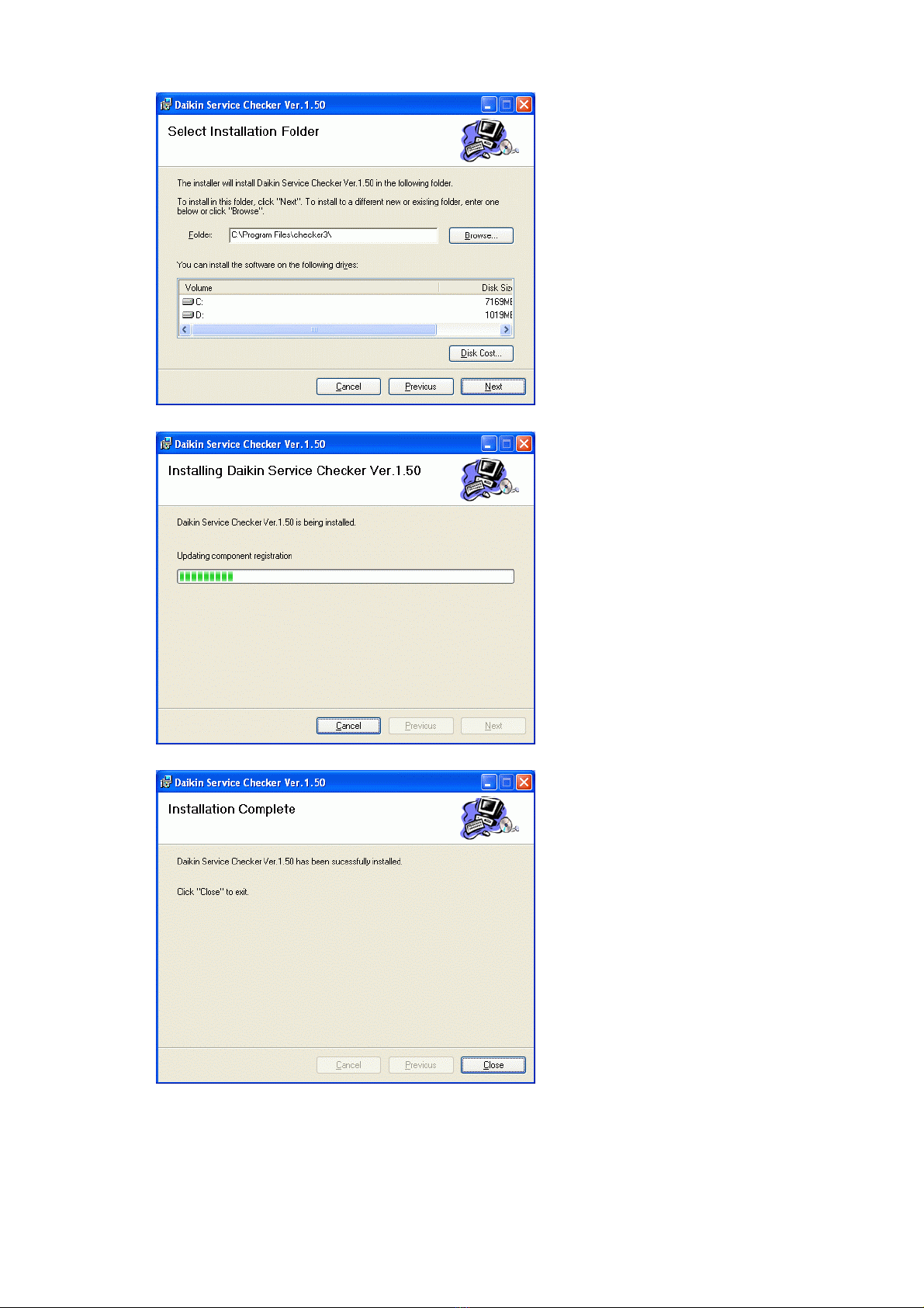
1.2 Installing of Checker TYPE 3 software--------------------------------------------------------7
1.3 Removing Checker TYPE 3 software ---------------------------------------------------------9
Chapter 2 Connection to air-conditioner 10
2.1 DIII-NET connection -----------------------------------------------------------------------------10
2.2 Sensor connection--------------------------------------------------------------------------------12
2.3 Switching on the power supply of Checker TYPE 3-------------------------------------14
Chapter 3 Starting up and ending of TYPE 3 software 15
3.1 Starting up of TYPE 3 software ---------------------------------------------------------------15
3.2 Setting of customer data------------------------------------------------------------------------16
3.3 Setting of SS data --------------------------------------------------------------------------------17
3.4 Setting of RS-232C(COM) port ---------------------------------------------------------------17
3.5 Ending of TYPE 3 software -------------------------------------------------------------------18
Chapter 4 Recording of operation data 19
4.1 Displaying of operation data-------------------------------------------------------------------19
4.1.1 Selection of customer data and others ---------------------------------------------29
4.1.2 Displaying of network map-------------------------------------------------------------23
4.1.3 Inputting of detailed data ---------------------------------------------------------------27
4.1.4 Displaying of operation data-----------------------------------------------------------29
4.2 Setting of recording ------------------------------------------------------------------------------31
4.2.1 Setting of periodical recording(in case of DIII-NET connection)-------------31
4.2.2 Setting of periodical recording (in case of only sensor input only)----------35
4.2.3 Setting of trigger recording -----------------------------------------------------------37
4.3 Centralized operation----------------------------------------------------------------------------39
Chapter 5 Playing back of operation data 41
5.1 Playing back of operation data----------------------------------------------------------------41
5.2 Playing back of network map------------------------------------------------------------------44
5.3 CSV output -----------------------------------------------------------------------------------------46
5.4 Data transfer ---------------------------------------------------------------------------------------48
List of applicable models 50
Specifications------------------------------------------------------------------------------------------------------------50

- 2 -
Introduction
i) Thank you for purchasing our Service Checker TYPE 3.1.
This Instruction Manual explains operation methods on how to use the Service Checker TYPE
3.1 and the TYPE 3 software.
Read carefully the Manual before using correctly the Service Checker TYPE 3.1 and the TYPE 3
software to use this checker correctly.
If improper handling of the Service Checker TYPE 3.1 and the TYPE 3 software is made without
observing correctly the notes specified in the Manual, it may cause accidents to human bodies or
failures of air conditioning systems.
Utilize fully the Manual with keeping it carefully in a proper place adjacent to the Service Checker
TYPE 3.1.
ii) Notes on safety :
Notes in the Manual of which negligence to observe may cause fatal or serious injuries to human
bodies are headed “WARNING”.
On the other hand, notes in the Manual of which negligence to observe may cause failures of
the air-conditioning systems are headed “CAUTION”.
iii) The Service Checker TYPE 3.1 has been developed for enhancing customer-service
capabilities of Daikin’s air- conditioners. It is a personal computer- monitored device which is
connected to an air-conditioner and reads out operation data (by temperature sensors, pressure
sensors, several kinds of solenoid valves, operating modes, etc.).
iv) The Service Checker TYPE 3.1 is possible to measure six temperature measurement points
and two pressure measurement points to monitor.
v) The contents of the Manual are subject to change without notice.
No part of this publication may be transmitted in any form without the prior permission of the
publisher.
We shall not have any responsibilities and liabilities on the results arising from operating the
Service Checker TYPE 3.1.
The contents of this Manual are valid as of Nov, 2012 and they may be modified for
improvement without any advance notice.
vi) CE marking
This is a group 1, class B product according to EN 55011. This means that this product does not
generate and/or use intentionally radio-frequency energy, in the form of electromagnetic
radiation, inductive and/or capacitive coupling, for the treatment of material or inspection /
analysis purpose and that it is suitable for use in domestic establishments and in establishments
directly connected to a low voltage power supply network which supplies buildings used for
domestic purposes.

- 3 -
Outline of the Manual
1. Firstly, read carefully the section of “Introduction”. Then, confirm the contents of the
packaged items by following the procedures of “Confirming of packaged items”. Then,
prepare for a personal computer.
2. Install the checker TYPE 3 software(English) into the personal computer by following the
procedures of “Chapter 1 Installing of TYPE 3 software”. Perform this installing at the time
of purchasing the Service Checker TYPE 3.1 and every version-up of the TYPE 3 software.
Refer to the “1.2 Deleting of TYPE 3 software”when the TYPE 3 software needs to be deleted
from the computer.
3. Refer to the “Chapter 2 Connection to air-conditioner”on the connecting between an
air-conditioner and the Service Checker TYPE 3.1 and the personal computer.
4. Refer to the “Chapter 3 Starting- up and ending of TYPE 3 software”on the starting- up and
ending of the TYPE 3 software and the setting of customer data and others.
5. After connecting the Service Checker TYPE 3.1 to the air-conditioner and the personal
computer, operation data and network map(linking between an indoor unit and an outdoor unit)
can be displayed by following the procedures of the “Chapter 4 Recording of operation data”.
Also, following the procedures of the “4.2 Setting of recording”, it is possible to record data
after setting to record them into the hard disc of the personal computer.
6. When recording, operation data and network map are recorded, while in playing back, the
operation data and network map are played back by following the procedures of the “5.1
Playing back of operation data”and the “5.2 Playing of network map”respectively.
Over view of service checker TYPE3

- 4 -
Confirming of packaged items
The Service Checker TYPE III consists of five standard items packaged as follows. Check up the
contents in the package.(See optional items in the “Specification”at the end of the Manual.)
1. Service Checker TYPE 3.1
(1) Service Checker TYPE 3.1
(2) RS-232C cable
D-sub 9 pin female - D-sub 9 pin female straight (2m)
(3) USB cable
A-B connector cable (2m) : only for power supply (DC 5V)
2. TYPE 3 Software-2 (Parts Number : 999151T)
CD-ROM : software, manual, and information
Caution
Please always use the cable (2m)
originally attached to the Checker TYPE 3.1
Caution
Please always use the cable (2m)
originally attached to the Checker TYPE 3.1

- 5 -
Preparation
Prepare the following
(1) Personal computer with the following specifications.
PC type :
MS Windows base PC
OS :
Windows 95/98/98SE/NT4.0/Xp/Vista/7 (32bit)
Serial Port :
RS-232C or USB-RS232C / PC card-RS232C adapter
(2) If the Checker TYPE 3 is connected to DIII-NET terminal for VRV-system air conditioners for
building, make up DIII-NET connecting cables as follows.
Procedures
Prepare the following signal wires. (Refer to the below notes.)
When connecting to an outdoor unit, it is appropriate for the signal wires to have 2 m in
length. When connecting to an indoor unit or wiring indoor from the outdoor unit, it is
possible to lengthen the signal wires within the limits of the DIII-NET length.
For control signal wiring, use vinyl cords or cables with two-core and sheathed as follow.
Vinyl cabtyre cylindrical cord VCTF JISC3306
Vinyl-insulated vinyl sheathed cable for control CVV JISC3401
Vinyl-insulated vinyl sheathed, cylindrical cable for control CVS JISC3401
Vinyl-insulated vinyl sheathed, cylindrical cable VVR JISC3342
600V vinyl cabtyre cable VCT JISC3312
(Note) Please do not use shielded cable.
Cautions: 1. Do not use multiple-cored wires with 3 cores or more.
2. Use wires with a cross section of 0.75mm2-1.25mm2.
3. Do not make wires bound in control- signal wiring. Do not make
long-distance wiring by having signal wires bound packed with tapes,
tie-laps and the like.
4. Wire the signal wires away from power lines to prevent the effects of
electric noise. Since Daikin’s air conditioners and related products will
generate much lower electric noises, it allows to have a distance of
minimum 50mm between the power lines and the control signal wires.

- 6 -
Name of each part
RS-232C connector
Power supply connector Power switch Serial Connector
(USB-B) Operating lamp Trigger Output
DIII-NET terminal Parallel connector
Sensor connector
RS-232C connector
ApersonalcomputerisconnectedbyusingRS-232Ccable. (Use
RS-232C cable originally attached to the Checker TYPE 3.1)
USB B-connector USB cable connector for power connection. (DC 5V)
( Use USB cable originally attached to the Checker TYPE 3.1)
Power switchWhen switching on, the red lamp is lit.
Operating lampWhen the Checker TYPE 3 is normally operated, the green lamp is
flashed.
Serial ConnectorNot use
Parallel connectorNot use
Trigger Output Not use
Sensor connectorThis connector is used for connecting the optional sensor kit .(Parts
Number : 999107T)
DIII-NET terminalThis terminal is for connecting the connecting cable made based on the
DIII-NET prepared in (2), the section of the “Preparation”.

- 7 - Chapter 1 Installing of TYPE 3 software
Chapter 1 Installing of TYPE 3 software
1.1 Obtaining Service Checker TYPE3 software
Obtaining Service checker TYPE3 software
1) CD-ROM (service parts 999151T)
2) Download from Internet Web Page (Only the case of Version UP)
http://airnet.jpn.org/chk/
software installer module : checker3_eng_v150.msi ( V150 is version )
1.2 Installing of Checker TYPE 3 software
When the Service Checker TYPE 3.1 is newly purchased, or the version-up of the TYPE 3
software (English) is made , install the new version of TYPE 3 software into the personal
computer.
(Note) When the version-up of the TYPE 3 software is made , be sure to delete the old
version in accordance with the procedures of the “1.2 Deleting of TYPE 3
software”before installing the new version of the software.
Procedures
1)Executing installer module. ( file double click. )
checker3_eng_v1xx.msi

- 8 - Chapter 1 Installing of TYPE 3 software
2)Selectinstallationfolder
3)Installingsoftware
4)Complete

- 9 - Chapter 1 Installing of TYPE 3 software
1.3 Removing Checker TYPE 3 software
When removing (uninstalling) the checker TYPE 3 software(English), follow the procedures
described below.
1) Use Installer module.
2) Use Control panel of Windows
Procedures
1) Use Installer module.
Fallowing screen is displayed when the old version is already installed.
Please select “Remove Daikin Service Checker Ver.1.xx”.
2) Using Control panel of Windows
Click “Add or Remove Programs”,
Select “checker TYPE3 software”and remove it.

- 10 - Chapter 2 Connection to air- conditioner
Chapter 2 Connection to air-conditioner
WARNING: 1. When using the Service Checker TYPE 3.1 in outdoor at rainy weather, be sure to
protect it from rain so that it becomes free from the danger of electric shock and
fires.
2. When leaving the Checker for a long time as it is, take proper measures against
leak current and rain water which may cause fires.
The connecting method between the Checker TYPE 3 and Daikin’s air-conditioning systems
consists of three : [DIII-NET connection] and [Sensor connection]. Select an appropriate one
depending on their features.
2.1 DIII-NET connection
Features of DIII-NET connection
・Possible to monitor simultaneously the operation data of multiple outdoor and indoor
units on the DIII-NET by connecting to VRV-system air-conditioners for building and
chillers conforming to the DIII-NET in internal and external data transmission.
Units conforming to the DIII-NET are shown in the [List of applicable units] at the end of
this Manual.
(Note)The range exceeding the limits of the DIII-NET expansion adapter (DTA109A1)
is not possible to monitor.
・To connect to the DIII-NET terminals(F1, F2) located on the PCB of an outdoor unit or
an indoor unit.
(Note)In case of an indoor unit, connect the end of the indoor unit not so as to create
sub-branching.
・When the Service Checker TYPE 3 is connected to the DIII-NET for the first time, be
careful to note that air conditioners on the DIII-NET will be set to restart standby for
several minutes.
In performing customer management, unless PCBs are replaced or the number of air
conditioners has changed, the air conditioners will not be set to the standby state from
the second time on by utilizing the previously recorded data of network map.
・The intervals of monitoring operation data are different depending on data items.
Besides, be careful to note that the operation data of an indoor unit are monitored at
intervals of several minutes.
・If the length of a connecting cable for the DIII-NET is within the limits of the DIII-NET, it
is possible to lengthen the cable.
・Not possible to use in combination with PCB connection but Sensor connection.

- 11 - Chapter 2 Connection to air- conditioner
Procedures
1) Screw tightly the clip-free end of DIII-NET connection cable made up by following the
item (3) of the “Preparation”at DIII-NET terminals(F1, F2) of the Checker TYPE 3. (If
an air-conditioner side is first connected and the resultant short-circuit should occur, it
may cause the failures of the air-conditioner.)
DIII-NET terminals
2)Connect the clipped side of the DIII-NET connection cable to the air conditioner.
WARNING : Be sure to connect the clipped side to the transmission terminal board (F1,
F2) of the air conditioner(outdoor unit or indoor unit). If wrongly connected
to power terminals of centralized equipment and the like, it may cause fatal
injuries by electrical shock to human bodies and failures of equipment.
CAUTIONS :1. In case of connecting to an indoor unit, connect the end of the indoor unit in
consideration of not creating sub-branching. If sub-branching is created,
communication errors may occur.
2. Do not need to correspond F1, F2 of the transmission terminal board of
the air conditioner to F1, F2 of the Checker TYPE 3 like F1-F1 or F2-F2
respectively.
Connect the clip-attached side of the DIII-NET connection cable to the transmission terminal
board (F1, F2) of the air conditioner.
If sensor connection is needed, proceed to the section of [2.3 Sensor connection], otherwise,
proceed to the section of [2.4 Switching on of the Checker TYPE 3].

- 12 - Chapter 2 Connection to air- conditioner
2.2 Sensor connection
Features of sensor connection
・In case of air conditioners not conforming to the DIII-NET connection, it becomes
possible to measure temperature and pressure by connecting the optional sensor kit
(Parts Number: 999107T).
・Six temperature points and two pressure points are possible to measure. Among
these points, two measurement points of temperature can be monitored as a signal of
DC 0-5V or DC 0-1V via measuring instrument by shifting the switch.
・Possible to use in combination with either the DIII-NET connection.
Procedures
1) Connect the sensors of a sensor kit to the Sensor connector at the front side of the
Checker TYPE 3.
WARNING : When measuring current and voltage, be sure to input a signal of
0-5VDC or 0-1VDC via measuring instrument to [A] and [V] terminals.
Do not connect these terminals to directly an object to be measured
current or voltage or add more than 5VDC to these terminals since fatal
injury to human bodies by electric shock or fires and failures of air
conditioning systems may be caused.
Connector
Cable of sensor kit
Th1Connect air temperature thermistor (for outdoor) Th1(white).
Th2Connect pipe temperature thermistor Th2(white).
Th3
Connect discharge pipe temperature thermistors Th3(red). Since the discharge
pipe temperature thermistors differs from other thermistors in a converting
(resistance value to temperature value) method, be sure to use the thermistor
Th3.
Th4Connect pipe temperature thermistor Th4(blue).
HPConnect high pressure sensor, HP(blue). Do not connect LP since HP differs
from LP in a converting(resistance value to pressure value) method.
LPConnect low pressure sensor, LP(red). Do not connect HP since LP differs from
HP in a converting(resistance value to pressure value) method.
Th5Connect air temperature thermistor(for indoor), Th1(white). To make Th5 valid,
place the upper switch in Th5 side. Aand Th5 are not possible to use
simultaneously.
A
Using optional cableA(red), connect to measuring instrument, To make A valid,
place the upper switch in A side. Aand Th5 are not possible to use
simultaneously. The conversion of a voltage signal from measuring instrument
into current is set by periodical recording in the “4.2 Setting of records”of the
TYPE 3 software.
Th6Connect air temperature thermistor (for indoor), Th4(blue). To make Th6 valid,
place the upper switch in Th6 side. V and Th6 are not possible to use
simultaneously.

- 13 - Chapter 2 Connection to air- conditioner
V
Using optional cable V (blue), connect to measuring instrument. To make V valid,
place the upper switch in V side. V and Th6 are not possible to use
simultaneously. The conversion of a voltage signal from measuring instrument into
voltage value is set by periodical recording in the “4.2 Setting of records”of TYPE 3
software.
(Note)In case of shifting [Th5] to [A] or [Th6] to [V] by using the switch of the
Checker TYPE 3, shift at a screen before the screen of [Display of network
map], otherwise, operation data will not be correctly recorded.
2) Set the sensor part to air conditioning systems.
* When measuring current and voltage, be sure to input a voltage signal of 0-5VDC or
0-1VDC via the measuring instrument to the sensor connectors of the Checker TYPE
3.
CAUTION
Please always use the sensors of Sensor Kit (Parts Number: 999107T)

- 14 - Chapter 2 Connection to air- conditioner
2.3 Switching on the power supply of Checker TYPE 3
Procedures
1) Connect the RS-232C cable attached to the Checker TYPE 3.1 to the RS-232C connector of
the Checker TYPE 3.1 and the Serial connector of a personal computer.
RS-232C connector (D-sub 9 pin)
USB cable (Power Supply) connector
2) Connect the Power Supply ( PC, AC-adapter, battery ) use USB cable, Power Supply connector
of the Checker TYPE 3. [ DC-5V ]
3) Turn on the Power Switch of the Checker TYPE 3.1. The red lamp of the Power Switch lights.
When the Checker TYPE 3 is normally operating, the green lamp flashes.
Power Switch Operation Lamp

- 15 -Chapter 3 Starting up and ending of TYPE 3
software
Chapter 3
Starting up and ending of TYPE 3
software
3.1 Starting up of TYPE 3 software
Procedures
1) Start Service Checker software by start menu.
2) After the Service Checker software is started, the following main menu is displayed.
[Record(F1)]:Press when recording.(Refer to Chapter 4 Recording of operation data)
[Play(F2)]:Press when monitoring recorded operation data.
(Refer to 5.1 Play of operation data.)
[Data transfer(F3)]:Recorded operation data and customer data are transferred to a
another folder. (Refer to 5.4 Data transfer.)
[Customer data(F4)]:Customer data are input and edited (Be sure to input customer ID .)
Recorded network map data are possible to see here.(Refer to 3.2
Setting of customer data and 5.2 Playing back of network map.)
[SS data(F5)]:SS data are normally input. (Refer to 3.3 Setting of SS data.)
[END(F12)]:The TYPE 3 software is ended. (Refer to 3.5 Ending of TYPE 3
software.)

- 16 -Chapter 3 Starting up and ending of TYPE 3
software
3.2 Setting of customer data
The TYPE 3 software manages the operation data of every customer. For that reason, be
sure to input customer ID at least. If the [Record only] without customer data management is
used in the DIII-NET connection, since restart standby is applied every time at the side of an
air conditioner, input customer data as much as possible.
(Note)Other than input from the following step of [Customer data] menu, the input of
customer data is possible by selecting the [Record(F1)] of the [Main menu].
Procedures
1) Press the [Customer data(F4)] in the [Main menu] to display the window of the [Customer
selection].
2) When customer data are newly input, press
the [New customer(F3)] to display the window of the next [Input customer data].
・When the current customer data need to be changed, select the customer by cursor, then,
press the [Edit customer data(F4)] to display the window of the next [Input customer
data].
・When customer data need to be deleted, press the [Delete customer(F9)]
3) Be sure to input the [Customer ID] with alphanumeric letters to identify customers.
4)Input the [Customer name] as much as possible to display in the windows of the [Selection
of operation data] and others.
5)Other items are only for memos.
6)When ending, press the [Record(F1)] button. When returning to previous state (input
waiting state) without recording, press the [Cancel(ESC)] button.

- 17 -Chapter 3 Starting up and ending of TYPE 3
software
3.3 Setting of SS data
Procedures
1) Press the [SS data(F5)] in the window of the [Main menu] to display the window of the
[Input SS data].
2) Input each item. Other than the item of [ In charge of ], use as memos.
・Input the name of the [Person in charge of SS] before pressing the [Add(F5)] button.
When deleting, select the name to be deleted by cursor before pressing the Delete(F6)].
・After completing the input, press the [Record(F1)] button.
・When returning without recording, press the [Cancel(ESC)].
3. 4 Setting of RS-232C(COM) port
The personal computer is equipped with the setting of RS-232C ports No. (COM1 to COM8).
Default setting is COM1.
Setup of PC MS-Windows setting.
If changing the ports, change by pressing the [Communication port(T)] in the menu of the
[Option].
A USB-RS232C adapter uses COM4
or
more than it in many cases.

- 18 -Chapter 3 Starting up and ending of TYPE 3
software
3. 5 Ending of TYPE 3 software
1) When ending the TYPE 3 software, press the [End(F12)] button in the window of the [Main
menu].
2) In case of ending the TYPE 3 software after recording and playing back, it is necessary to
repeat several times pressing the [Cancel(ESC)] to return to the window of the [Main
menu]. In this case, by pressing the ×button in the extreme upper right of the
window, the TYPE 3 software will end at once.
[ Example of the display of operation data]
3) Also, by selecting the [End(X)] of the menu of [Function (F)] located in the extreme upper
left of the window, the TYPE 3 software will end at once.

- 19 - Chapter 4 Recording of operation data
Chapter 4 Recording of operation data
The TYPE 3 software manages data by the hierarchy structure of [customer-network map-operation data].
Customer Network map Operation data
System 1: Mar. 23
System 2: Mar. 23
System 1: Feb. 11
A building 1F
:
System 1: Apr. 2
A building 2F :
A customer
: :
B customer : :
: : :
4.1 Displaying of operation data
4.1.1 Selecting of customer data and others
Procedures
(1) Press the [Record(F1)] in the [Main menu] to display the window of the
[Customer selection].
(2) In this window of the [Customer selection], input customer-related data.
Recording data only without relating to customers is also possible.
Table of contents
Popular Diagnostic Equipment manuals by other brands

Topdon
Topdon ArtiLink 500 Update instruction

Hologic
Hologic Genius Review Station Operator's manual

Bosch
Bosch Rexroth PS5000 Commissioning and operating instructions

Harbor
Harbor CEN-TECH TIMING LIGHT Owner's manual & safety instructions

TecMate
TecMate VacuumMate Allweather Service manual

INFERUM
INFERUM ROFES E01C Operating and service manual