Direct Airscale PILATUS PC 9 Owner's manual
1
1.80m 1.68m ASYMM
3.7kg 4.8kg
install Kit
install Kit
YES
YES
TECHNICAL INSTRUCTIONS
May change without notice
50dm
2
SERVOS
Ailerons
Rudder + wheel
Elevator
Flaps
Retract
Gas or bec
Direct Airscale
Code : 3642
scale model
PILATUS PC 9

2
ank you for choosing a Direct Airscale model. If you have any problems do not hesitate to consult
our website. Especially the section CLUB DA (Direct Airscale club) for each plane where you will nd
information. You also can consult me directly by phone but try to be a maximum shorter . ank
you. You also can participate in the interaction you’ll nd at general chapter CLUB DA.
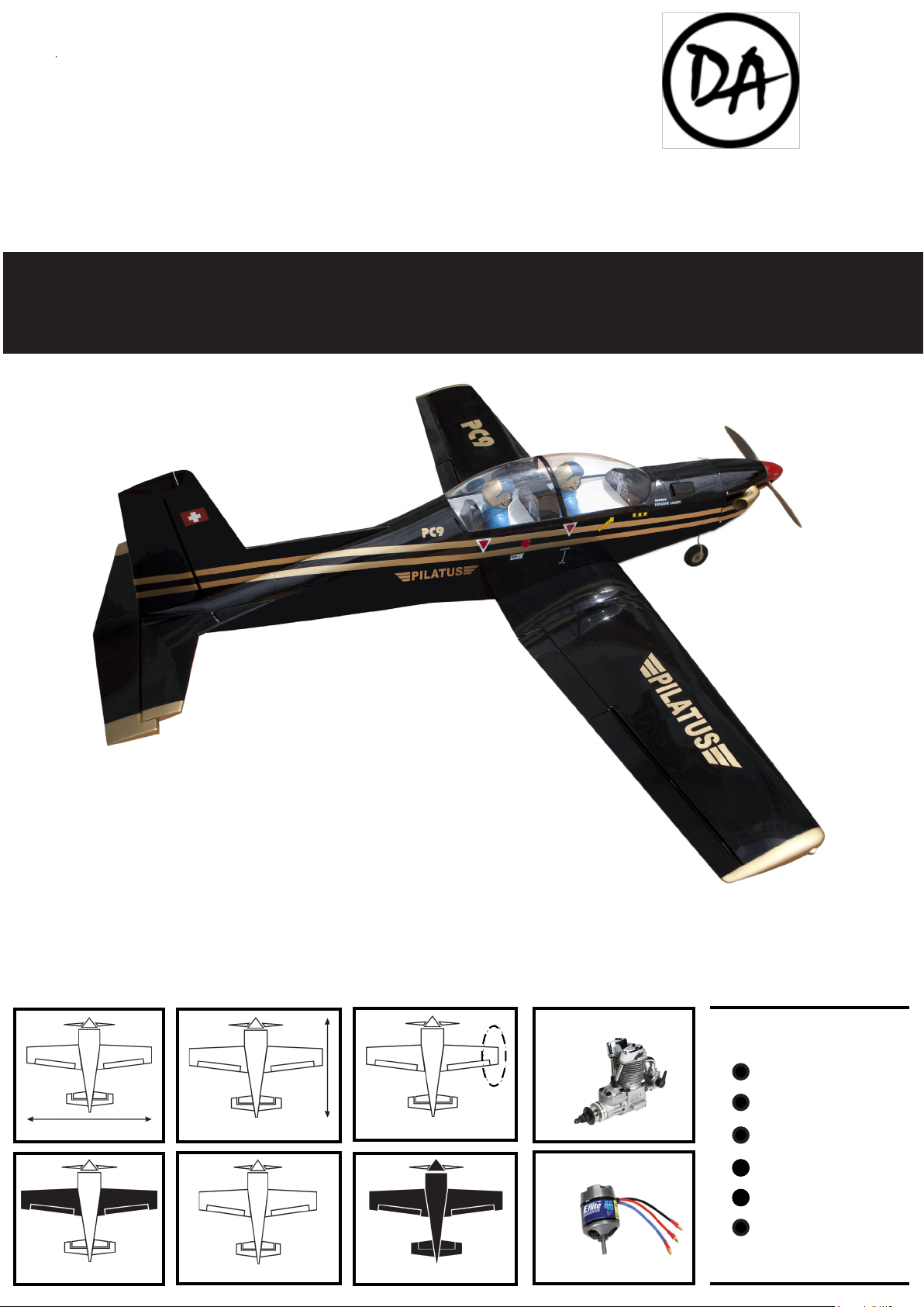
Our PILATUS PC 9 is presented in a black and gold livery military parade, held by the Swiss
and Bulgarian armies among others. It is a light aircra that we have equipped a tricycle me-
chanical retracts. A kit for the installation of an electric motor is provided. It is naturally sta-
ble with wings in the format “hang” rectangular double dihedral tailplane and rejected very
rear of the fuselage. Proudly camped on its tricycle landing gear, it is pleasant to look at and fun
to drive. Quite presentable in meetings warbird or interclub. In all modesty is a must 1.80m that
will feel. To respect the genuine our model PC9 is equipped with aps that this type of wing al-
lows to train the reactions induced by the output of the landing aps. e aps are slot eect which
enhances their sweetness and power liing. All characteristics that should take a lot of votes.
CONGRATULATIONS.
WARNING
ADDITIONAL ITEMS REQUIRED.
TOOLS AND SUPPLIES.
• Propulsion set depending your choice :
gas or electric.
• Radio set minimum 4 channels.
• 4 servos.
• Propeller.
• Electric lipo pack or Ni-Mh.
• Switch or Bec controller and fuse.
If you are inexperienced with basic r/c ight we strongly recommended you contact the nearest
model aircra club. Experienced members will help you to install additional accessories to put your
aircra airworthy. e club will ensure your training and you will avoid ying illegally and destroy
your aircra from the rst ight.
• ick cyanoacrylate glue.
• 30 minute epoxy.
• Electric drill.
• Assorted drill bits.
• Modelling knife.
• Straight ruler.
• Miscellaneous sandpaper.
• 90° builder’s triangle.
• Wire cutters.
• Tape & T-pin
• A set of small keys 6 section
• A set of screw drivers
KIT CONTENTS.
• Light and rigid balsa and plywood construc-
tion
• Fuselage and wings built and Oracover ® cov-
ered
• Decoration and lettering print on cover
• Painted clear canopy
• 2 Pilots included
• 2 dash boards
• Rigid wire landing gear
• Mechanical retracts included (3 wheels)
• Controlled front wheel
• Spinner
• Fiber cowl
• Methanol engine installation kit (tank, motor
mount, ...)
• Electric motor installation kit (part wooden
lipo kit ...)
• All mounting hardware , screws , ttings ,
linkages , ...
• English mounting instructions with photos
• Country translations send beside
3
To prevent damage to the coating cover
your workbench with a cloth or blanket.
Do not pull on the packaging you may be
too much pressure and break your plane.
Carefully unpack the wings and fuselage us-
ing scissors or a cra knife. Open aware of
hardware apart and sort all parts in order to
understand who goes where. Store in a se-
ries of independent small boxes. When you
work, do not let scews, miscellaneous hard-
ware, accessories and tools below dierent
parts of your aircra. Check constantly. Be-
fore gluing carefully prepare all the parts,
try them and if needed dig slots a bit more.
Work slowly and read many time techni-
cal instructions to be sure to understand all
tricks.Repeat gestures before using glue. If
overows do not use acetone on coatings
and plastics. Oen simply wipe with a paper
towel.
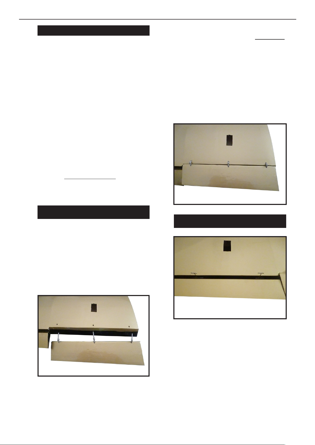
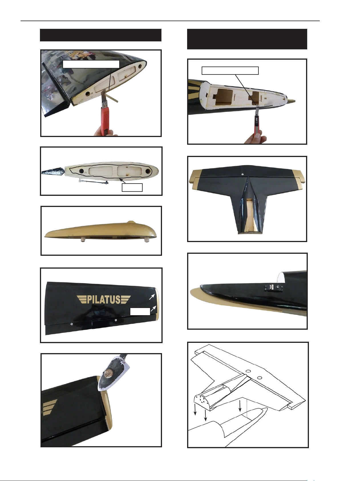
To ensure the mobility of aps we planned
cylindrical hinges. e trick is that these
hinges are installed at 90°mean 45°on each
side. See photos. at way when you leave
the aps deport these hinges and shutters
create a slot eect that brings the li in ad-
dition to limiting the braking eect of tur-
bulence aps and thus repel the stall speed.
All hinges are pre-installed but not glued.
Before removal for sizing carefully locate all
positions with a ballpoint pen not to create a
gap for the collage.Note the middle hinge so
that the same amount is depressed in both
parties. Plant may also serves as a needle
stop which provides the necessary play and
exibility. If you use the cyano coat once all
the hinges with a veil of cyano.
Drill your 45° holes about 2mm before the
edge. Be careful not to cross! Cut hinges
taking into account the thickness of the
wing. Introduce all hinges. e hinges must
be pressed closer, gently so that the oset is
reasonable. To check the alignment of the 3
hinges use simply your eye. If you need to
reduce the oset just push a bit more. Flaps
are manipulated to test the exibility of op-
eration. Monitoring the orientation of the
hinge pins to be perpendicular to the rota-
tional movement.
HINGING THE FLAPS.
INSTALLING HINGES GENERAL.
TIPS FOR ASSEMBLY

4
HINGING THE ELEVATORS.
Aileron control horn : See below pictures.
HINGING THE RUDDER.
HINGING THE AILERONS.
AILERONS CONTROL HORN.
M3x40mm
2 sets.
Paste all hinges on the xed parts (wings,
tail).
Aer a reasonable period of time depend-
ing on the glue used permanently installed
mobile appendages ensuring that there is a
slight clearance for free movement of fric-
tion . During drying maneuver the pieces
to make sure everything runs smoothly. If
epoxy clean the excess glue with paper. Do
not use acetone.
Proceed as described at general, then check
the ns are aligned wingtip and move free.
See below pictures.
Proceed as described at general, then check
the edge ns are aligned and move free.
See below pictures.
Proceed as described at general, then check
the edge ns are aligned and move free.
See below pictures.
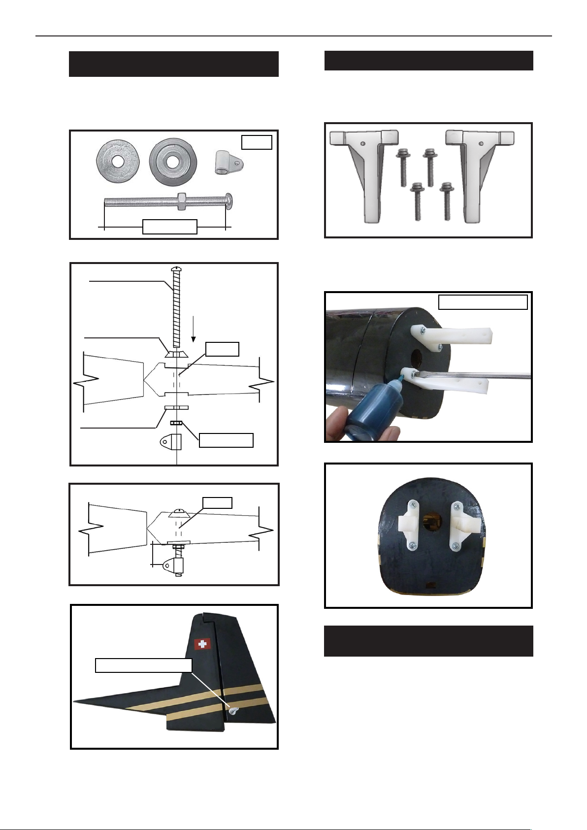
Hinge.

5
Repeat the process for the ap control horn.
FLAP CONTROL HORN.
CONTROL HORN
M3 SCREW.
Epoxy.
Epoxy.
18mm
Aluminum washer.
Aluminum washer.
M3 Lock nut.
Install the elevator control horn using the
same method as same as the aileron control
horns.
ELEVATOR CONTROL HORN.
M3x45mm
2 sets.
Aluminum washer.
Aluminum washer.
Control horn M3
Epoxy.
Elevator.
M3 Lock nut.
Horizontal
Stabilizer.
Epoxy.
Horizontal
Stabilizer.
18mm.
Wing bottom.
Aileron
Aileron control horn.
Elevator control horn.
Flap control horn.
6
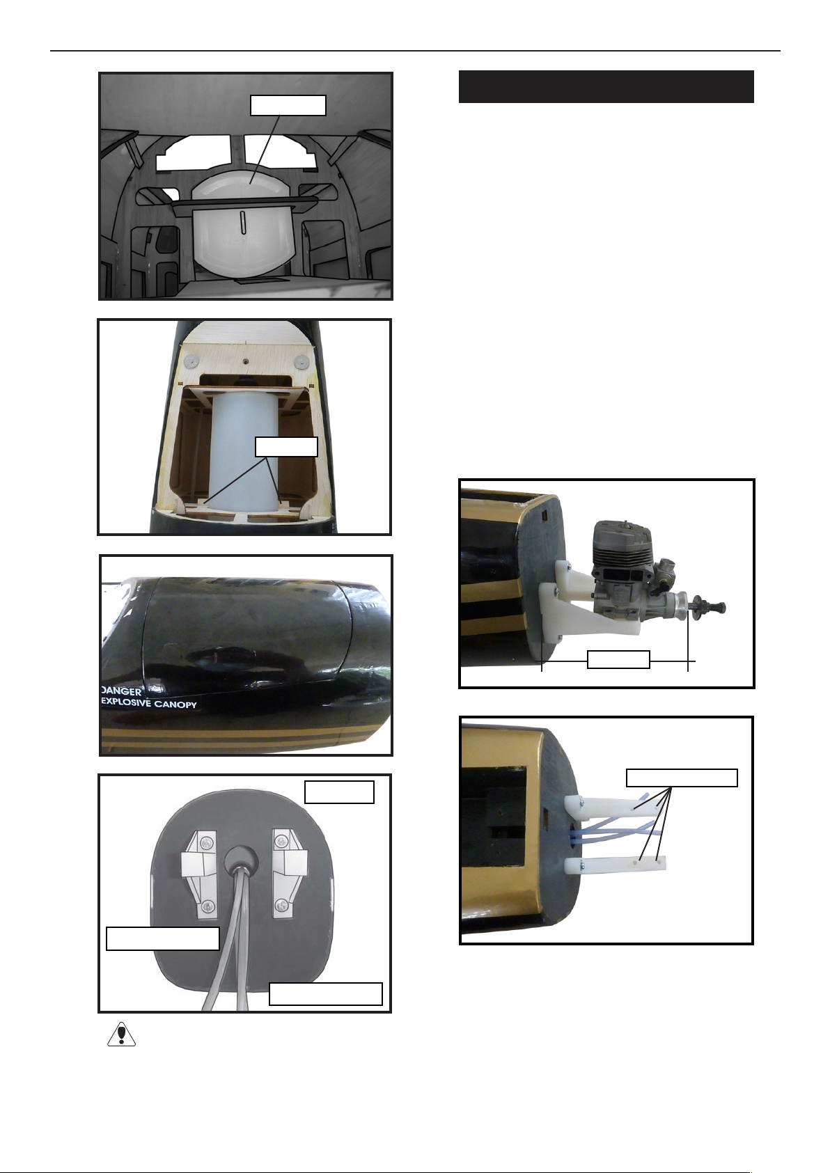
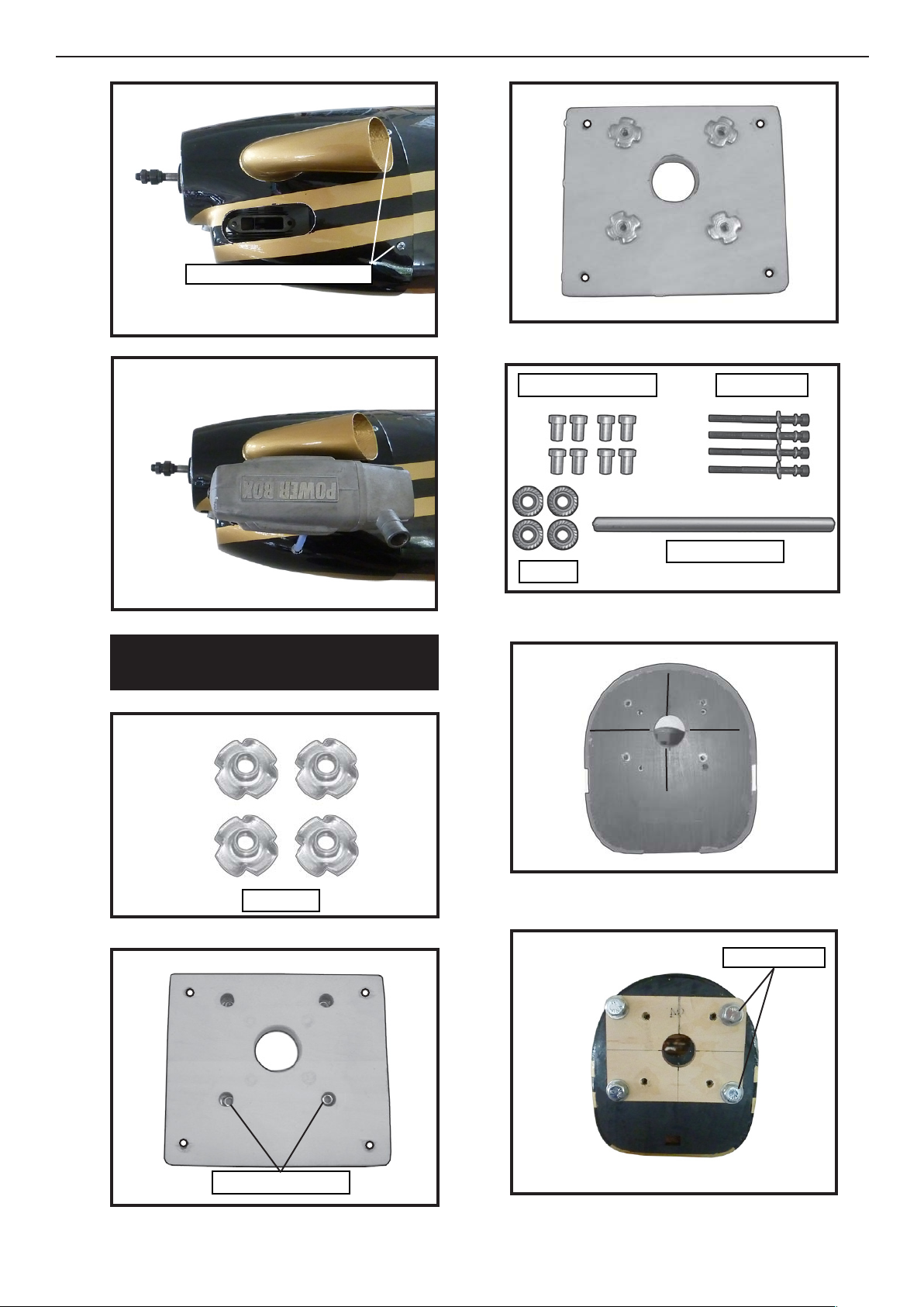
See below pictures. Make yourself the tem-
plate of your engine on paper.
Mark and drill 4 holes for engine mount.
Insert 4 blind nuts to rewall.
Control horn M3
Aluminum washer.
Rudder
Fuselage
Aluminum washer.
Epoxy.
M3 Lock nut.
Epoxy.
Rudder.
Fuselage
18mm
ENGINE MOUNT INSTALLATION.
.
M4x30mm
INSTALLING THE STOPPER
ASSEMBLY.
1) Using a modeling knife, carefully cut
o the rear portion of one of the 3 nylon
tubes leaving 1/2” protruding from the
rear of the stopper. is will be the fuel
pick up tube.
Rudder control horn.
read locker glue.
Using the same techniques used aileron
control horn. See picture below.
RUDDER CONTROL HORN.
M3x45mm
2 sets.

7
2) Using a modeling knife, cut one length
of silicon fuel line. Connect one end of
the line to the weighted fuel pick up and
the other end to the nylon pick up tube.
3) Carefully bend the second nylon tube up
at a 45º angle. is tube is the vent tube.
Carefully use a lighter or heat gun to per-
menently set the angle of the vent tube.
Vent tube. Fuel pick up
Fuel fill tube.
tube.
Important: When the stopper assembly is
installed in the tank, the top of the vent tube
should rest just below the top surface of the
tank. It should not toch the top of the tank.
4) Test t the stopper assembly into the tank.
It may be necessary to remove some of the
ashing around the tank opening using a
modeling knife. If ashing is present, make
sure none falls into the tank.
5) With the stopper assembly in place, the
weighted pick-up should rest away from the
rear of the tank and move freely inside the
tank. e top of the vent tube should rest just
below the top of the tank. It should not touch
the top of the tank.
FUEL TANK INSTALLATION.
You should mark which tube is the vent
and which is the fuel pickup when you attach
fuel tubing to the tubes in the stopper. Once
the tank is installed inside the fuselage, it may
be dicult to determine which is which.
6) When satised with the alignment of the
stopper assembly tighten the 3 x 20mm ma-
chine screw until the rubber stopper expands
and seals the tank opening. Do not over-
tighten the assembly as this could cause the
tank to split.
Glow Engine.
C/A glue.
8
Blow through one of the lines to ensure
the fuel lines have not become kinked inside
the fuel tank compartment. Air should ow
through easily.
1) Install the pushrod housing through the
predrilled hole in the rewall and into the
servo compartment. e pushrod housing
should protrude 1/4” out past the front of the
rewall. Make a Z-Bend 1/4” from one end
of the plain wire pushrod.
2) Place your engine onto the engine mount.
Adjust the engine is centered of the adges of
the engine case.
4) Remove the engine. Using an drill bit,
drill the mounting holes through the engine
mount at the four location marked.
5) Bolt the engine to the engine mount using
the four machine screws. Double check that
all the screws are tight before proceeding.
6) Attach the Z-Bend in the pushrod wire to
the throttle arm on the carburetor.
3) When you are satised with the alignment,
mark the location of the engine mounting.
MOUNTING THE ENGINE.
Vent tube.
Fuel pick up tube.
Fuel ll tube.
C/A glue.
150mm
4.2mm diameter.
Fuel tank.

9
COWLING.
1) Slide the berglass cowl over the engine
and line up the back edge of the cowl with
the marks you made on the fuselage then
trim and cut as shown.
2) While keeping the back edge of the cowl
ush with the marks, align the front of the
cowl with the cranksha of the engine. e
front of the cowl should be positioned so the
cranksha is in nearly the middle of the cowl
opening. Use the spinner backplate as a
guide. Hold the cowl rmly in place using
pieces of masking tape.
3) Install the muer and muer extension
onto the engine and make the cut out in the
cowl for muer clearance. Connect the fuel
and pressure lines to the carburetor, muer
and fuel ller valve. Secure the cowl to fuse-
lage using the M3x10mm screws (4).
Because of the size of the cowl, it may be nec-
essary to use a needle valve extension for the
high speed needle valve. Make this out of suf-
cient length 1.5mm wire and install it into
the end of the needle valve. Secure the wire in
place by tightening the set screw in the side of
the needle valve.
Machine screw M4x30mm
Pushrod.
Trim and cut.
Trim and cut.
Trim and cut.
Needle valve.
10
Electric Conversion ( Ep Power)
(OPTION).
Blind nut.
Diameter = 5.2mm
Aluminum spacers.
Aluminum tube.
M6x120mm.
M5 Nut
M6x120mm
Machine screw M3x10mm

1111
Aluminum spacers.
Aluminum tube.
B
A
4 sets.
Aluminum tube.
BB
B B
Electric motor.
155mm
Electric motor.
M4x15mm
1
1
C/A glue.
Battery.
Remove top hatch.

12
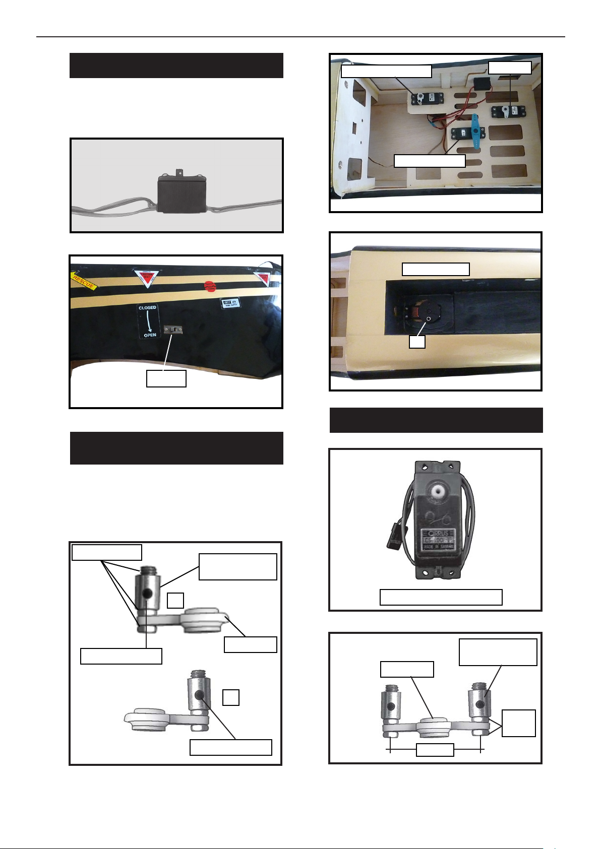
INSTALLING THE FUSELAGE SERVOS.
.
Because the size of servos dier, you
may need to adjust the size of the precut
opening in the mount. e notch in the
sides of the mount allow the servo lead to
pass through.
1) Install the rubber grommets and brass
collets onto the throttle servo. Test t the
servo into the aileron servo mount.
2) Secure the servos with the screws pro-
vided with your radio system.
rottle servo.
Steering servo arm.
Rudder servo.
Retract servo.
Cut.
Elevator servo.
Install the spinner backplate, propeller
and spinner cone.
SPINNER INSTALLATION.
e propeller should not touch any
part of the spinner cone. If it does, use a
sharp modeling knife and carefully trim
away the spinner cone where the propel-
ler comes in contact with it.
1313
Switch.
THROTTLE - RETRACT SERVO ARM
INSTALLATION.
SERVO GEAR INSTALLATION.
Install adjustable servo connector in the
servo arm as same as picture below:
INSTALLING THE SWITCH.
Install the switch into the precut hole in
the side of fuselage.
Servo arm.
Adjustable servo
connector.
Loctite secure.
Diameter = 2mm
Diameter = 3mm
2
1Servo for retractable only.
Adjustable servo
connector.
Loctite
secure.
Servo arm.
25mm
rottle servo arm.
Steering servo.
Rudder.
Retract servo.
2

14
PUSHROD INSTALLATION.
GEAR INSTALLATION.
135mm
145mm
1
23
1
2
3
1
Electric wire.
Wing bottom.
M3x15mm
Remove covering.

15
servo arm.
Open Position
Close Position
servoarm. 12mm.
25mm.
16
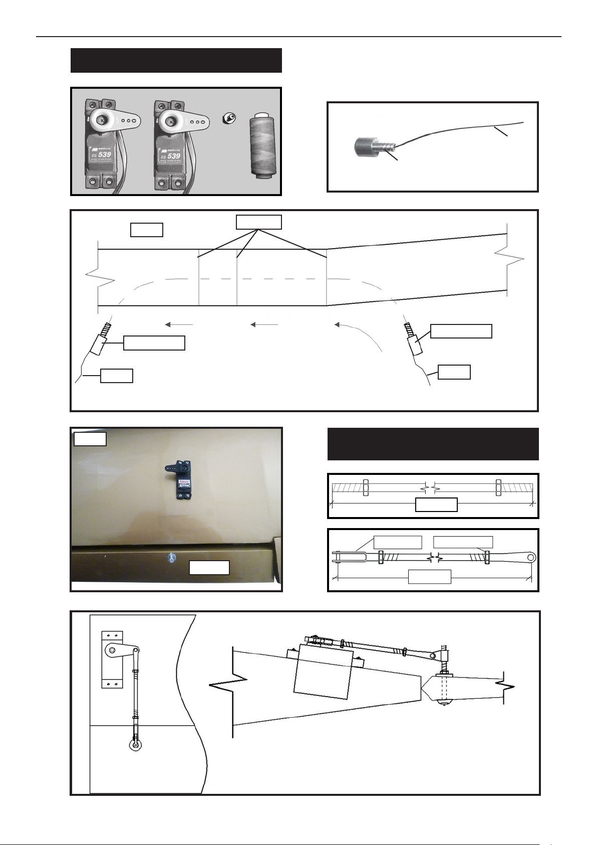
INSTALLING THE AILERON SERVOS.
Servos
.
Small weight
.
Thread
Small weight.
String.
Installing the aileron servo in place using
the same techniques used to ap servo.
Wing. Wing rib.
Small weight.
Small weight.
String. String.
Attach the string to the servo lead and carefully thread it though the wing.
M3 lock nut.
M3 clevis.
.
110mm
90mm
AILERON PUSHROD HORN
INSTALLATION.
Wing.
Wing.Aileron
Aileron.
Wing.
Aileron.
AILERON PUSHROD HORN INSTALLATION.
17
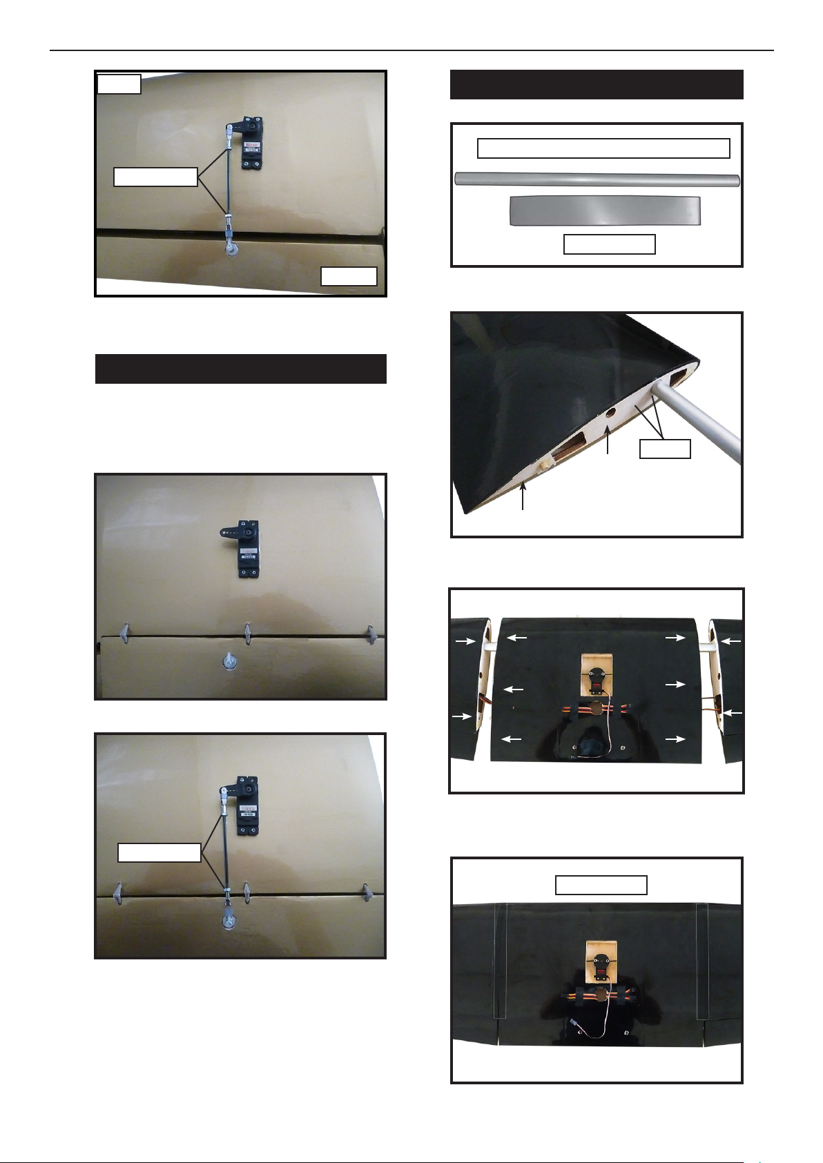
Repeat the proccedure for the other wing.
Repeat the procedure for ap pushrod
as same as aileron pushrod.
INSTALLING THE FLAP PUSHROD.
WING ASSEMBLY.
Wing.
M3 lock nut.
Aileron.
M3 lock nut.
Aluminum tube diameter = 19x 806 mm
Masking tape.
Epoxy
Masking tape.
18
INSTALLING THE HORIZONTAL
STABILIZER.
WING TIP INSTALLATION.
Remove the covering.
Epoxy.
Epoxy.
Remove the covering.
1919
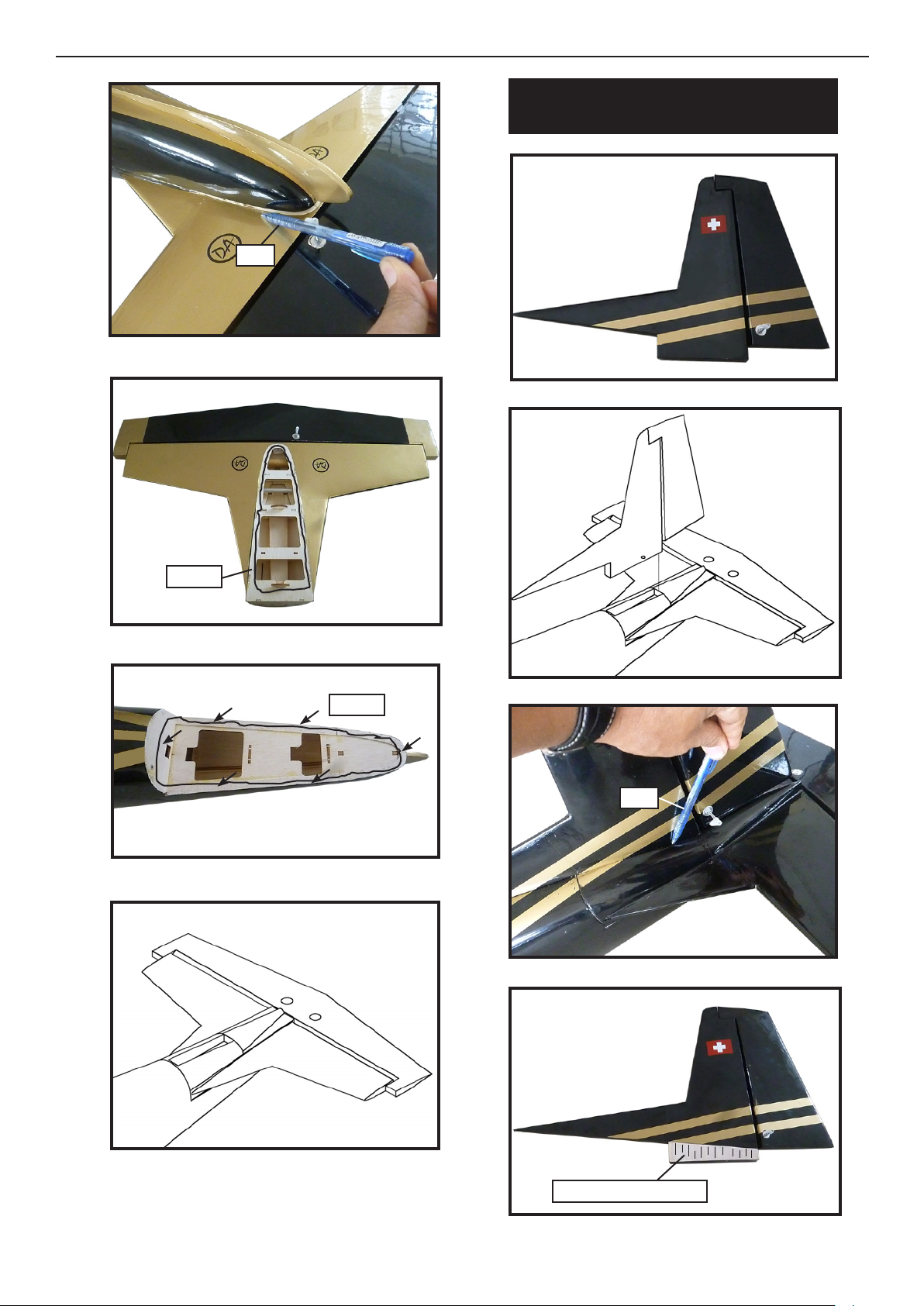
INSTALLING THE VERTICAL
STABILIZER.
Pen.
Epoxy.
Epoxy.
Pen.
Remove the covering.
20
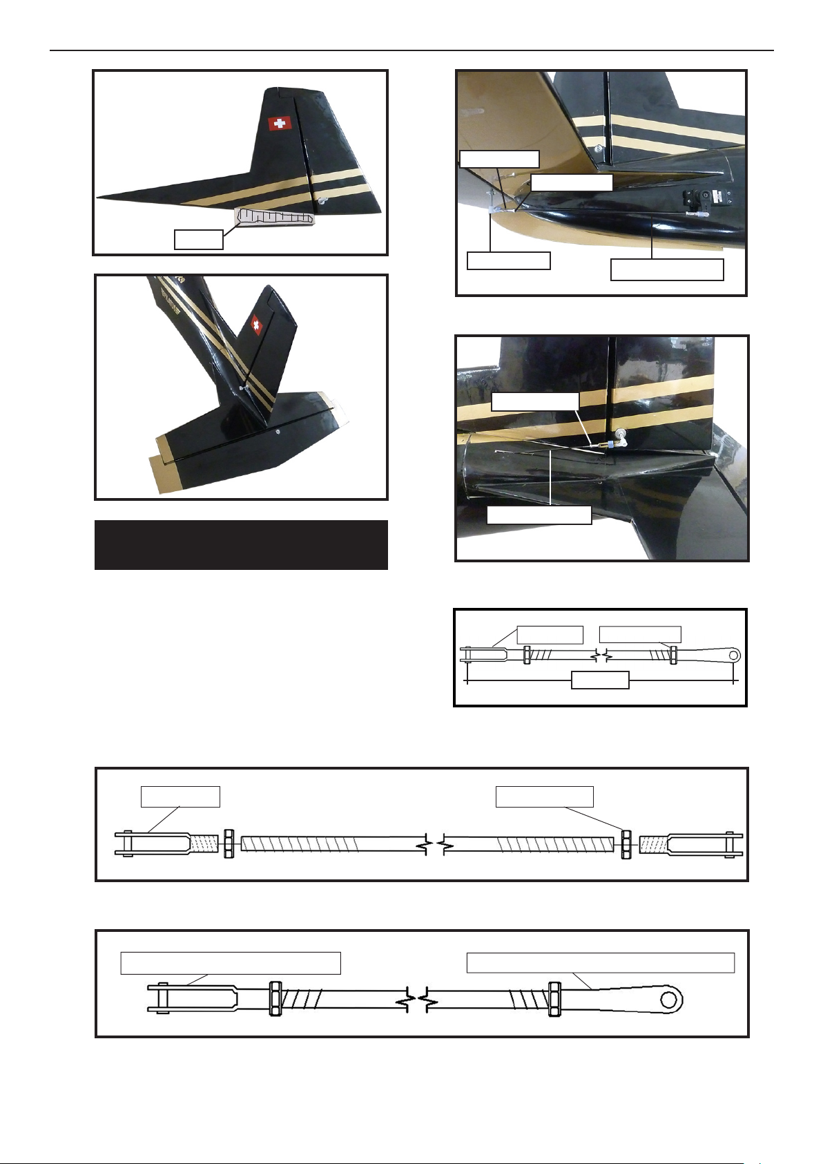
Attach to servo arm in fuselage. Attach to elevator - rudder control horn.
M2 Lock
nut.M2 clevis.
Epoxy.
ELEVATOR - RUDDER PUSHROD
HORN INSTALLATION.
1) Elevator and rudder pushrod assembly
follow pictures below.
2) Install servos arm to servos. Notice the
position of the servo arms on the servos.
See picture below.
Elevator pushrod.
Contro horn.
Metal clevis.
M3 lock nut.
Rudder pushrod.
M2 lock nut.
M3 lock nut.
M3 clevis.
155mm
Table of contents
Other Direct Airscale Toy manuals


Popular Toy manuals by other brands

Banzai
Banzai Mini Golf Fun Park manual

Eduard
Eduard Zoom B-1B interior S.A. manual

WARCRADLE STUDIOS
WARCRADLE STUDIOS Dystopian Wars Templehof Battlefleet Assembly instructions

Hasbro
Hasbro TRANSFORMERS BUMBLEBEE VOICE CHANGER MASK manual

Hasbro
Hasbro PLAYSKOOL Magic Screen Learning Desk manual

Hasbro
Hasbro Cybertron Cannonball 81239 instructions


