Direct Airscale SPACE WALKER ELECTRO Owner's manual

1
1.58m 1.16m ASYMM
2.1kg 2.9kg
install Kit
install Kit
NO
YES
SERVOS
TECHNICAL INSTRUCTIONS
May change without notice
space walker electro
Ailerons
Rudder + wheel
Elevator
Flaps
Retract
Gas or bec
41dm
2
Direct Airscale
Code : 4131
scale model

2
ank you for choosing a Direct Airscale model. If you have any problems do not hesitate to consult
our website. Especially the section CLUB DA (Direct Airscale club) for each plane where you will nd
information. You also can consult me directly by phone but try to be a maximum shorter . ank
you. You also can participate in the interaction you’ll nd at general chapter CLUB DA.
For our SPACE WALKER electro we respected the concept of scale to provide a lightweight,
economical airplane engine but can collect any aerobatics as it is true that wood (balsa and ctp) and
good quality wing serious manufacturer key can provide you with any “envelope” that will accept any
physical injuries you inict it. . . Signicantly higher than the real one! To tell you whether or not you
y model. One day yes, one day not, can be a good answer. Our decor is dierent from that intended
by designers like spider-man but still takes one chosen by many U.S. homebuilders. Have fun, let you
go, y quiet or clownish, our “space walker” is made for this.
CONGRATULATIONS.
WARNING
ADDITIONAL ITEMS REQUIRED.
TOOLS AND SUPPLIES.
• Propulsion set depending your choice :
gas or electric.
• Radio set minimum 4 channels.
• 4 servos.
• Propeller.
• Electric lipo pack or Ni-Mh.
• Switch or Bec controller and fuse.
If you are inexperienced with basic r/c ight we strongly recommended you contact the nearest
model aircra club. Experienced members will help you to install additional accessories to put your
aircra airworthy. e club will ensure your training and you will avoid ying illegally and destroy
your aircra from the rst ight.
• ick cyanoacrylate glue.
• 30 minute epoxy.
• Electric drill.
• Assorted drill bits.
• Modelling knife.
• Straight ruler.
• Miscellaneous sandpaper.
• 90° builder’s triangle.
• Wire cutters.
• Tape & T-pin
• A set of small keys 6 section
• A set of screw drivers
KIT CONTENTS.
• Light and rigid balsa and plywood construc-
tion
• Fuselage and wings built and Oracover ® cov-
ered
• Decoration and lettering placed
• 2 Pilots included
• 2 dash boards
• Aluminum landing gear
• Fiber wheel cover decorated
• Large diameter wheels
• Controlled tail wheel
• Spinner
• Fiber cowl
• Electric motor installation kit (part wooden
lipo kit ...)
• All mounting hardware, screws, ttings, link-
ages, ...
• Mounting instructions in English with photos
• Country translation send beside

3
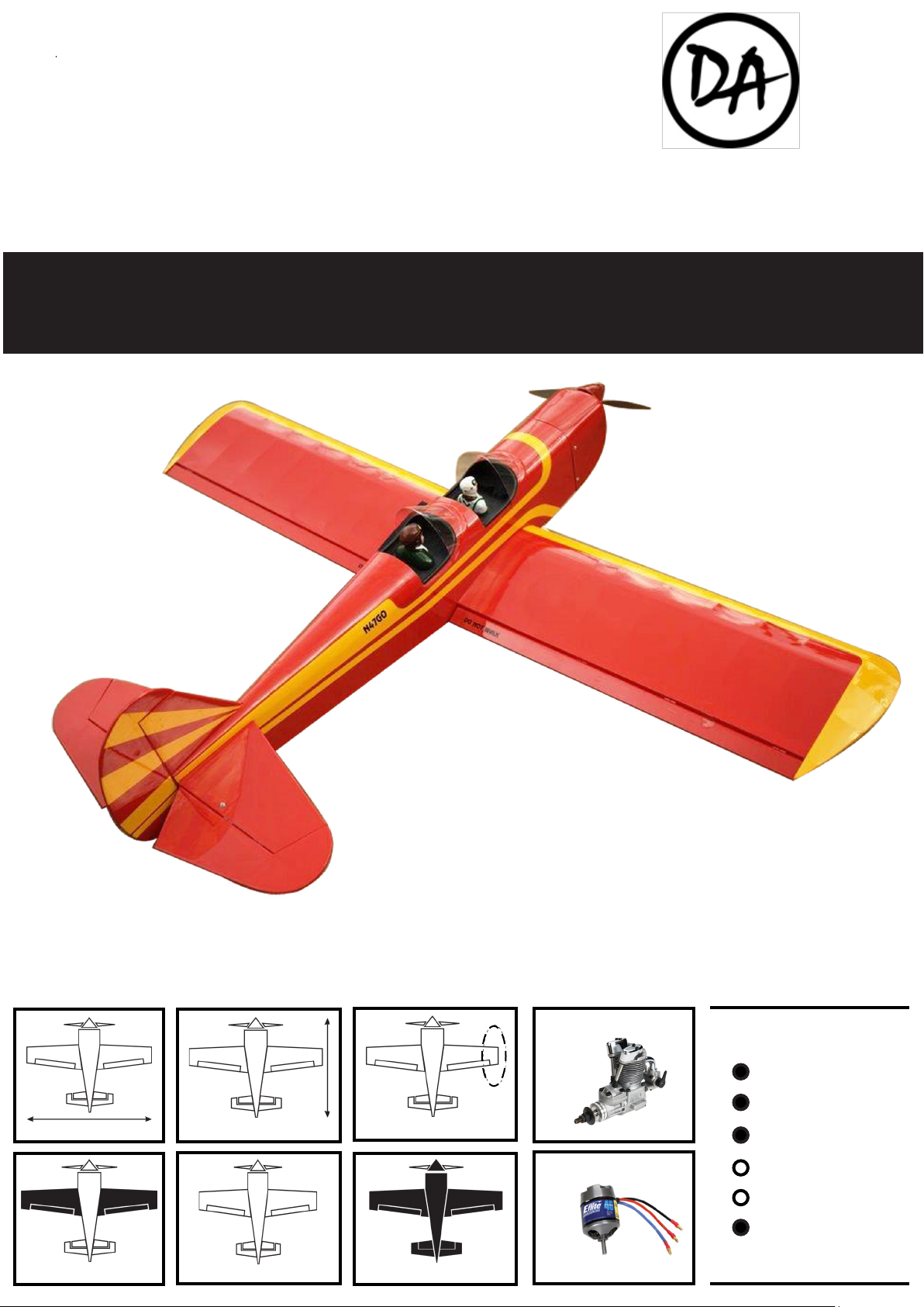
HINGING THE AILERON.
e control surfaces, including the ai-
lerons, elevators, and rudder, are pre-
hinged with hinges in stalled, but the
hinges are not glued in place. It is im-
perative that you properly adhere the
hinges in place per the steps that fol-
low using a high-quality thin C/A glue.
Note :
1) Carefully remove the aileron from one
of the wing panels. Note the position of the
hinges.
2) Remove each hinge from the wing panel
and aileron and place a T-pin in the center of
each hinge. Slide each hinge into the aileron
until the T-pin is snug against the aileron.
is will help ensure an equal amount of
hinge is on either side of the hinge line when
the aileron is mounted to the wing panel.
3) Slide the aileron on the wing panel until
there is only a slight gap. e hinge is nowcen-
tered on the wing panel and aileron. Remove
theT-pinsandsnugtheaileronagainstthewing
panel. A gap of 1/64” or less should be main-
tained between the wing panel and aileron.
.
Hinge
T-pin
4) Deect the aileron and completely satu-
rate each hinge with thin C/A glue. e ailer-
ons front surface should lightly contact the
wing during this procedure. Ideally, when
the hinges are glued in place, a 1/64” gap or
less will be maintained throughout the lengh
of the aileron to the wing panel hinge line.
e hinge is constructed of a special
material that allows the C/A to wick
or penetrate and distribute through-
out the hinge, securely bonding it to
the wood structure of the wing panel
and aileron.
Note :
5) Turn the wing panel over and deect the
aileron in the opposite direction from the
opposite side. Apply thin C/A glue to each
hinge, making sure that the C/A pene-
trates into both the aileron and wing panel.
6) Using C/A remover/debonder and a pa-
per towel, remove any excess C/A glue that
may have accumulated on the wing or in the
aileron hinge area.
7) Repeat this process with the other wing
panel, securely hinging the aileron in place.
8) Aer both ailerons are securely hinged,
rmly grasp the wing panel and aileron to
make sure the hinges are securely glued and
cannot be pulled out. Do this by carefully
applying medium pressure, trying to sepa-
rate the aileron from the wing panel. Use
caution not to crush the wing structure.
T-pin
C/A glue.

4
HINGING THE ELEVATOR.
Glue the elevator hinges in place using the
same techniques used to hinge the ailerons.
HINGING THE RUDDER.
Glue the rudder hinges in place using the
same techniques used to hinge the ailerons.
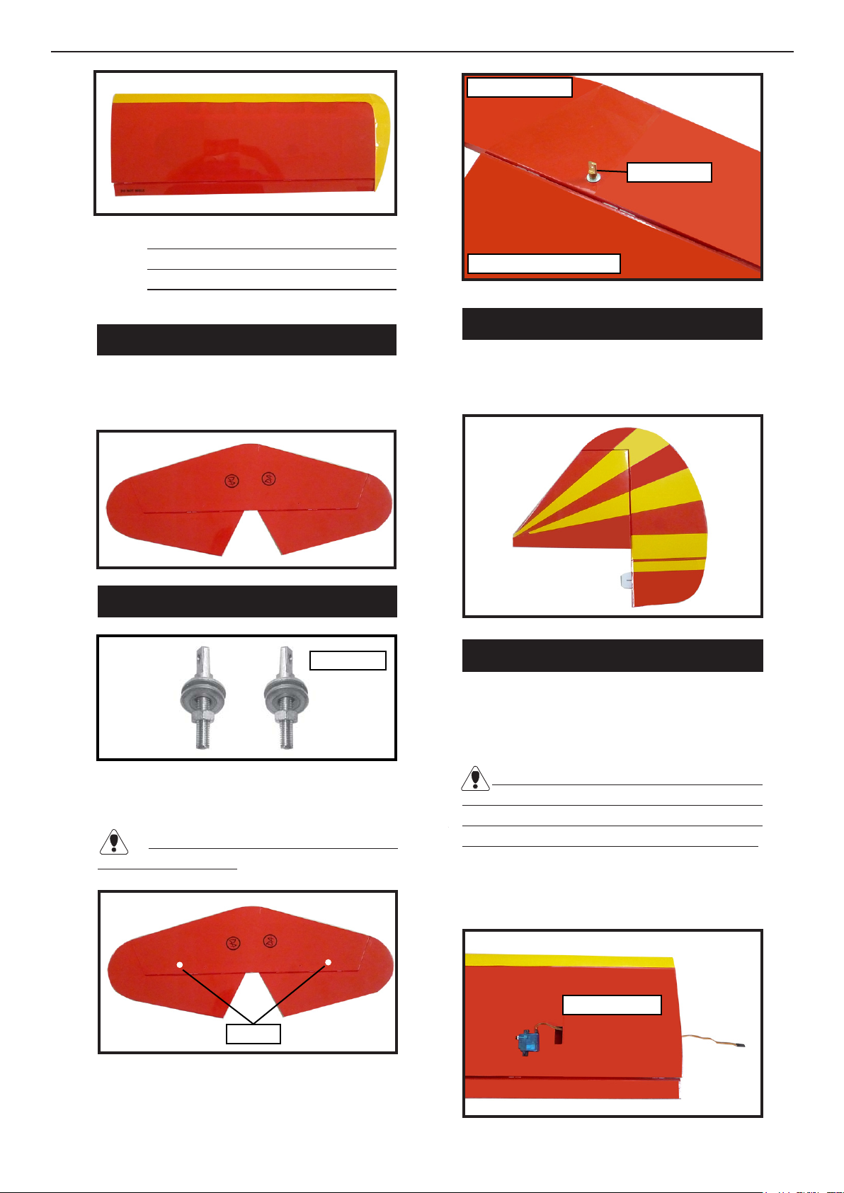
TURNBUCKLE INSTALLATION.
e hole location of turnbuckle shown in
picture below.
Attach the thread to the servo lead and
carefully thread it though the wing.
e mounting holes of turnbuckle was
pre-drilled at factory.
Installing the turnbuckle for tail strut of
horizontal n as same as pictures below.
.
INSTALLING THE AILERON SERVO.
1) Install the rubber grommets and brass
collets onto the aileron servo. Test t the
servo into the aileron servo mount.
Because the size of servos dier, you may
need to adjust the size of the precut opening
in the mount. e notch in the sides of the
mount allow the servo lead to pass through.
Work the aileron up and down sev-
eral times to “work in” the hinges
and check for proper movement.
Note :
3x20mm.
32mm
Tail n bottom.
Horizontal n bottom.
Turnbuckle.
Wing bottom.

5
1) Using a ruler & pen to draw a straight line
as picture below.
6) Connect the linkage as shown and secure
the control wire with a wire keeper.
2) Locate the two nylon control horns, two
nylon control horn backplates and four ma-
chine screws.
3) Position the aileron horn on the bottom
side of aileron. e clevis attachment holes
should be positioned over the hinge line.
4) Using a 1mm drill bit and the control
horns as a guide, drill the mounting holes
through the aileron halves.
5) Mount the control horns by inserting the
screws through the control horn bases and
aileron halves, then into the mounting back-
plates. Do not overtighten the screws or the
backplates may crush the wood.
2) Secure the servos with the screws provid-
ed with your radio system.
INSTALLING THE AILERON LINKAGE.
2 x 20mm
Control horn.
Mounting Plate.Mounting Screws.

6
Repeat the procedure for the other aileron
servo.
INSTALLING THE FUSELAGE SERVOS.
Because the size of servos dier, you may
need to adjust the size of the precut opening
in the mount. e notch in the sides of the
mount allow the servo lead to pass through.
2) Install the rubber grommets and brass
collets onto the throttle servo. Test t the
servo into the aileron servo mount.
3) Secure the servos with the screws provid-
ed with your radio system.
1) Locate and cut out the covering lm from
the servo holes in both sides of fuselage.
HORIZONTAL STABILIZER.
1) Using a ruler and a pen, locate the center-
line of the horizontal stabilizer, at the trailing
edge, and place a mark. Use a triangle and
extend this mark, from back to front, across
the top of the stabilizer. Also extend this
mark down the back of the trailing edge of
the stabilizer.
2) Using a modeling knife, carefully remove
the covering at mounting slot of horizontal
stabilizer ( both side of fuselage).
3) Slide the stabilizer into place in the precut
slot in the rear of the fuselage. e stabilizer
should be pushed rmly against the front of
the slot.
Wire keeper.
Servo arm.
Right side.
Remove covering.
Right side.
Left side.
Elevator servo.
Rudder servo.
Center line.

7
4) With the stabilizer held rmly in place,
use a pen and draw lines onto the stabilizer
where it and the fuselage sides meet. Do this
on both the right and le sides and top and
bottom of the stabilizer.
Pen.
5) Remove the stabilizer. Using the lines you
just drew as a guide, carefully remove the
covering from between them using a mod-
eling knife.
6) When you are sure that everything is
aligned correctly, apply C/A glue to the top
and bottom of the stabilizer mounting area
and to the stabilizer mounting platform sides.
When cutting through the covering
to remove it, cut with only enough pres-
sure to only cut through the covering it-
self. Cutting into the balsa structure may
weaken it.
Remove covering.
.
VERTICAL STABILIZER
INSTALLATION.
1) Using a modeling knife, remove the cover-
ing from over the precut hinge slot cut into
the lower rear portion of the fuselage. is
slot accepts the lower rudder hinge.
Hinge.
Hinge slot.
2) Glue the vertical n in place using as same
as techniques used to installing the horizon-
tal n.

8
When cutting through the covering
to remove it, cut with only enough pressure
to only cut through the covering itself. Cut-
ting into the balsa structure may weaken it.
3) Slide the vertical stabilizer back in place.
Using a triangle, check to ensure that the ver-
tical stabilizer is aligned 90º to the horizontal
stabilizer.
Control horn installation as same as meth-
od of aileron wing. See pictures below.
CONTROL HORN INSTALLATION.
Pen.
Remove covering.
90º
Vertical
Stabilizer.
Horizontal
Stabilizer.
Hinge.
C/A glue.
Elevator control horn.

9
Pushrod install as same as method of push-
rod os aileron. See pictures below.
PUSHROD INSTALLATION.
Elevator control horn.
Rudder control horn.
Pushrod.
Pushrod.
e tail strut system assembly follow pic-
tures below.
INSTALLING TAIL STRUT SYSTEM.
Plastic trap.
Plastic trap.
MOUNTING THE TAIL WHEEL.
1) Set the tail wheel assembly in place on
the plywood plate. e pivot point of the tail
wheel wire should be even with the rudder
hinge line and the tail wheel bracket should
be on the plywood plate.

10
MOUNTING THE CONTROL CLASP.
1) Align the tail wheel wire so that the wire
is parallel with the bottom of the rudder. e
control clasp has a predrilled hole through
the top of it. Slide this hole onto the tail
wheel wire while sliding the clasp over the
bottom of the rudder.
2) Using a ruler and a pen place a mark onto
the bottom of the rudder. e back edge of
the clasp should line up with this mark.You
may nd it necessary to bend the tail wheel
wire down slightly so it lines up with the
clasp without binding.
2) Using a pen, mark the locations of the
two mounting screws. Remove the tail wheel
bracket and drill 1mm pilot holes at the loca-
tions marked.
3) Secure the tail wheel bracket in place us-
ing two 3x10mm wood screws. Be careful
not to overtighten the screws.
3) While holding the clasp rmly in place,
use a pen and outline the clasp onto the rud-
der.
4) Remove the clasp, and using a modeling
knife, remove the covering from inside the
lines you drew. Use 220 grit sandpaper and
carefully roughen the inside surface of the
nylon clasp.
5) Slide the clasp back into position and
carefully glue it into place using Kwik Bond
in C/A. Hold the clasp in place until the
glue completely cures. Secure by 1 machine
screw.
1) Assemble and mounting the wheel pants
as shown in the following pictures.
2) Follow diagram below for wheel pant in-
stallation :
WHEEL AND WHEEL PANTS
INSTALLATION.
Control clasp.
Machine Screw
2x12mm
3x12mm

11
Caution when cutting the axles and
wear protective goggles.
3) You have to trim each axle using a tool
cutting and cut-o wheel.
Wheel Collar.
Axle.
Wheel.Nut.
Wheel Pant.
Landing Gear.
Nut.
(2) Washer.
8mm
46mm
(2) Wheel Collar.
Axle.
Wheel.
Nut.
Nut.
(2) Washer.
Landing gear.

12
4) A drop of C/A glue on the wheel collar
screws will help keep them from coming lose
during operation.
1) e blind nuts for securing the landing
gear are already mounted inside the fuselage.
ere are 2 mounting box for your option. It
is depended your motor size.
2) Using the hardware provided, mount the
main landing gear to the fuselage.
Repeat the process for the other wheel.
INSTALLING THE MAIN LANDING
GEAR.
INSTALLING ELECTRIC MOTOR.
4x20mm
MOTOR BOX.
Diameter 4.5 mm.
MOTOR BOX.
Blind nut.
Epoxy glue.
Motor.

13
INSTALLING THE BATTERY.
See pictures below :
Slide the berglass cowl over the engine and
line up the back edge of the cowl with the
marks you made on the fuselage then trim
and cut.
Secure the cowl with the screw provide with
hardware.
COWLING INSTALLATION.
See pictures below :
DUMMY ENGINE INSTALLATION.
See pictures below :
Speed control.
Tie wrap or rubber band.
Battery.
3x10mm
Trim and cut.
Glue.

14
INSTALLING THE RECEIVER.
WINDSHIELD INSTALLATION.
PILOT INSTALLATION.
1) Remove the fastening wire as same as pic-
ture below.
2) Glue the pilot into the position.
Receiver.
Tie wrap.
Antenna wire.
2x8mm Machine screw.
Fastening wire.
Glue.
Glue.

15
ATTACHMENT WING-FUSELAGE.
Bolt the wing to fuselage.
Insert two wing panels as pictures below.
Wing tube.
Wing bolt.
7.5 - 8 cm
BALANCING.
1) It is critical that your airplane be balanced
correctly. Improper balance will cause your
plane to lose control and crash. e center
of gravity is locate back from the leading
edge of the wing, measured at wing ROOT.
e value is 7.5-8cm
2) If the nose of the plane falls, the plane is
nose heavy. To correct this rst move the bat-
tery pack further back in the fuselage. If this
is not possible or does not correct it, stick
small amounts of lead weight on the fuselage
sides under the horizontal stabilizer. If the
tail of the plane falls, the plane is tail heavy.
To correct this, move the battery and receiver
forward orif this is not possible, stick weight
onto the rewall. When balanced correctly,
the airplane should sit level or slightly nose
down when you li it up with your ngers.
CONTROL THROWS.
1) We highly recommend setting up the
SPACE WALKER BI-158 using the control
throws listed at right. We have listed control
throws for both Low Rate (initial test ying/
sport ying) and High Rate (aerobatic y-
ing).
2) Turn on the radio system, and with the
trim tabs on the transmitter in neutral, center
the control surfaces by making adjustments
to the clevises or adjustable servo connec-
tors. e servo arms should be centered also.

16
4) By moving the position of the adjustable
control horn out from the control surface,
you will decrease the amount of throw of that
control surface. Moving the adjustable con-
trol horn toward the control surface will in-
crease the amount of throw.
3) When the elevator, rudder and aileron
control surfaces are centered, use a ruler and
check the amount of the control throw in
each surface. e control throws should be
measured at the widest point of each sur-
face!
INITIAL FLYING / SPORT FLYING
Ailerons : 3/16” up 3/16” down
Elevator : 3/8” up 3/8” down
Rudder : 1” right 1” le
AEROBATIC FLYING
Ailerons : 3/8” up 3/8” down
Elevator : 1” up 1” down
Rudder : 2” right 2” le
Do not use the aerobatic settings for initial
test ying or sport ying.
We will not give you any instructions in this part. is is not the role of a
manufacturer and it would be unrealistic and even dangerous to think we can make
adjustments prior to rst ight just by reading a document. It necessarily requires a
minimum of experience and you must get closer to a driver or experienced trainer.
is will verify the magnitude and direction of the control and various other settings.
Also good battery recharging, fuel quality and other studio and eld accessories.
We draw your attention to the danger of handling aircra with electric motors.
Unless it is equipped with sophisticated security, there is a very real risk of starting
the engine inadvertently especially when you need to put all the radio equipment
energized to start setting the servos. We recommend surrounding the propeller of a
large, heavy cloth bath towel for example avoiding such injuries.
Also the recharging of lipos may pose a risk of re or explosion. is happens
when drivers hasty dangerously increase the rate of charge their batteries. e other
drawback is to signicantly reduce their lifespan.
To start your propulsive you must use specic start table, or any other devices
provided in your club or recommended by your tutelagefederation.
Never y alone especially as our lands are oen in remote locations where it is
dicult to nd assistance in the event of an accident.
If you follow these guidelines from the common sense you go in with a lot of
fun in the world of model airplanes.
e Direct Airscale team wishes you good ights
MAIDEN FLY.
DA a large Vietnamese experience for flying scale airplanes
This manual suits for next models
1
Table of contents
Other Direct Airscale Toy manuals