Direct Airscale Recreation 148 Owner's manual
1
Direct Airscale
Code : from 2113 to 2157
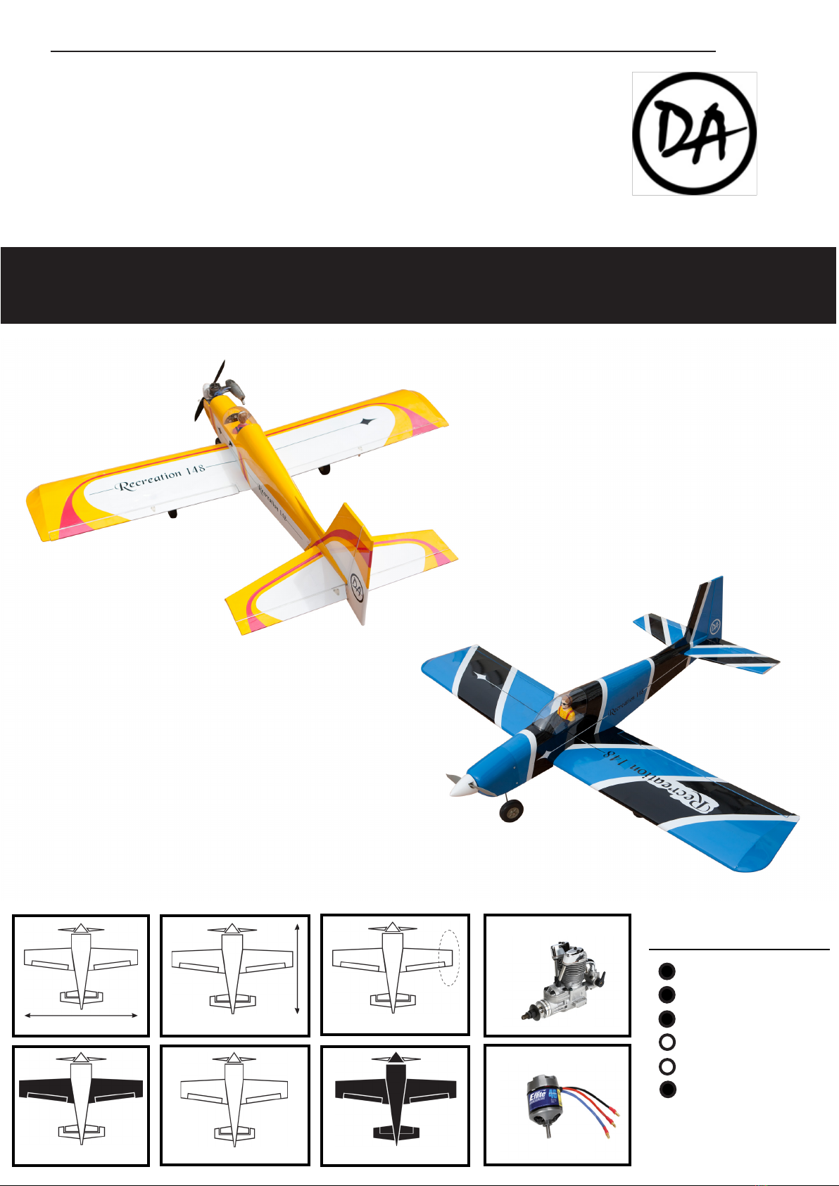
easy series
Recreation 148
Ailerons
Rudder + wheel
Elevator
Flaps
Landing gear
Gas or bec
1.48m 1.23m ASYMM
19.4dm 2 2.2kg 3.0kg
install Kit
install Kit
YES
YES
SERVOS
TECHNICAL INSTRUCTIONS
May change without notice

2
WARNING.
If you are inexperienced with basic r/c ight we strongly recommended you contact the nearest
model aircra club. Experienced members will help you to install additional accessories to put your
aircra airworthy. e club will ensure your training and you will avoid ying illegally and destroy
your aircra from the rst ight.
ADDITIONAL ITEMS REQUIRED.
TOOLS AND SUPPLIES.
KIT CONTAIN.
• Propulsion set depending your choice :
gas or electric.
• Radio set minimum 4 channels.
• 4 servos.
• Propeller.
• Electric lipo pack or Ni-Mh.
• Switch or Bec controller and fuse.
• ick cyanoacrylate glue.
• 30 minute epoxy.
• Electric drill.
• Assorted drill bits.
• Modelling knife.
• Straight ruler.
• Miscellaneous sandpaper.
• 90° builder’s triangle.
• Wire cutters.
• Tape & T-pin
• A set of small keys 6 section
• A set of screw drivers
ank you for choosing a Direct Airscale model. If you have any problems do not hesi-
tate to consult our website. Especially the section CLUB DA (Direct Airscale club) for each
plane where you will nd information. You also can consult us directly by phone but try
to be a maximum shorter . ank you. You also can participate in the interaction
you’ll nd at general chapter CLUB DA.
e RECREATION is the perfect aircra to relax and, or, progress.Low wing for
a neutral behavior and good reactivity.Facilitates learning inverted ight.Rectangu-
lar wing.Moderate dihedral. Good ratio length / size (0.84) for a good pitch toler-
ance and easy balancing. Tricycle to protect the propeller in case of global return sca-
brous. Large diameter wheels for tracks average. Logo DA (direct airscale) very visible
to the underside (below) for tracking that will help you in your aerobatic training.A
plane leisure without moderation. We kept an asymmetric biconvex prole for our
Recreations to maintain good fault tolerance in particular variations of li landing.
is is the plane that you will start to really play in the third dimension.
CONGRATULATIONS.
• Light and rigid balsa and plywood construc-
tion
• Hull and wings constructed and covered
• Clear canopy
• 1 Pilot included
• Decoration sticker board
• Rigid aluminium landing gear
• Large wheels diameter
• Controlled front wheel
• Spinner
• Gas engine accessories (tank, engine mount,...)
• Electric engine accessories (lipo wooden part,
mounting kit,...)
• All neccessary hardware and accessories in-
cluded
• Document for assembly (Several languages).
3
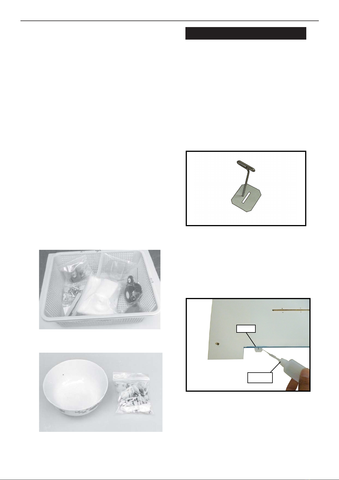
HINGING THE AILERON.
e control surfaces, including the ai-
lerons, elevators, and rudder, are pre-
hinged with hinges in stalled, but the
hinges are not glued in place. It is im-
perative that you properly adhere the
hinges in place per the steps that fol-
low using a high-quality thin C/A glue.
Note :
1) Carefully remove the aileron from one
of the wing panels. Note the position of the
hinges.
2) Remove each hinge from the wing panel
and aileron and place a T-pin in the center of
each hinge. Slide each hinge into the aileron
until the T-pin is snug against the aileron.
is will help ensure an equal amount of
hinge is on either side of the hinge line when
the aileron is mounted to the wing panel.
3) Slide the aileron on the wing panel until
there is only a slight gap. e hinge is nowcen-
tered on the wing panel and aileron. Remove
theT-pinsandsnugtheaileronagainstthewing
panel. A gap of 1/64” or less should be main-
tained between the wing panel and aileron.
.
.
To avoid scratching your new aer-
oplane we suggest that you cover
your workbench with an old tow-
el. Keep a couple of jars or bowls
handy to hold the small parts aer
you openthe bags. Please trial t
all parts. Make sure you have the
correct parts and that they t and
are aligned properly before gluing!
is will ensure proper assembly
as the RECREATION 148 is made
from natural materials and minor
adjustments may have to be made.
e paint and plastic parts used in
this kit are fuel proof. However,
they are not tolerant of many harsh
chemicals including the following:
paint thinner, cyano-acrylate glue
accelerator, cyanoacrylate glue de-
bonder and acetone. Do not let
these chemicals come in contact
with the colours on the covering
and the plastic parts.
NOTE :
Hinge
C/A glue
4
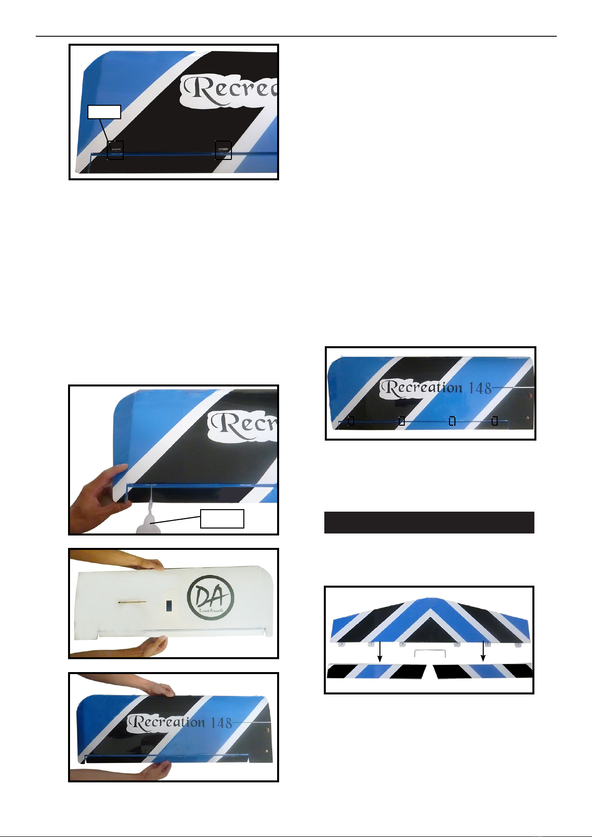
HINGING THE ELEVATOR.
4) Deect the aileron and completely satu-
rate each hinge with thin C/A glue. e ailer-
ons front surface should lightly contact the
wing during this procedure. Ideally, when
the hinges are glued in place, a 1/64” gap or
less will be maintained throughout the lengh
of the aileron to the wing panel hinge line.
e hinge is constructed of a special
material that allows the C/A to wick
or penetrate and distribute through-
out the hinge, securely bonding it to
the wood structure of the wing panel
and aileron.
Note :
5) Turn the wing panel over and deect the
aileron in the opposite direction from the
opposite side. Apply thin C/A glue to each
hinge, making sure that the C/A pene-
trates into both the aileron and wing panel.
6) Using C/A remover/debonder and a pa-
per towel, remove any excess C/A glue that
may have accumulated on the wing or in the
aileron hinge area.
7) Repeat this process with the other wing
panel, securely hinging the aileron in place.
8) Aer both ailerons are securely hinged,
rmly grasp the wing panel and aileron to
make sure the hinges are securely glued and
cannot be pulled out. Do this by carefully ap-
plying medium pressure, trying to separate
the aileron from the wing panel. Use caution
not to crush the wing structure.
Work the aileron up and down sev-
eral times to “work in” the hinges
and check for proper movement.
Note :
Hinge
C/A glue
1) Locate the item for this section of the
manual.
2) Carefully remove the elevator from one of
the horizontal stabilizer panels. Note the po-
sition of the hinges.
5
Glue the elevator hinges in place using the
same techniques used to hinge the ailerons.
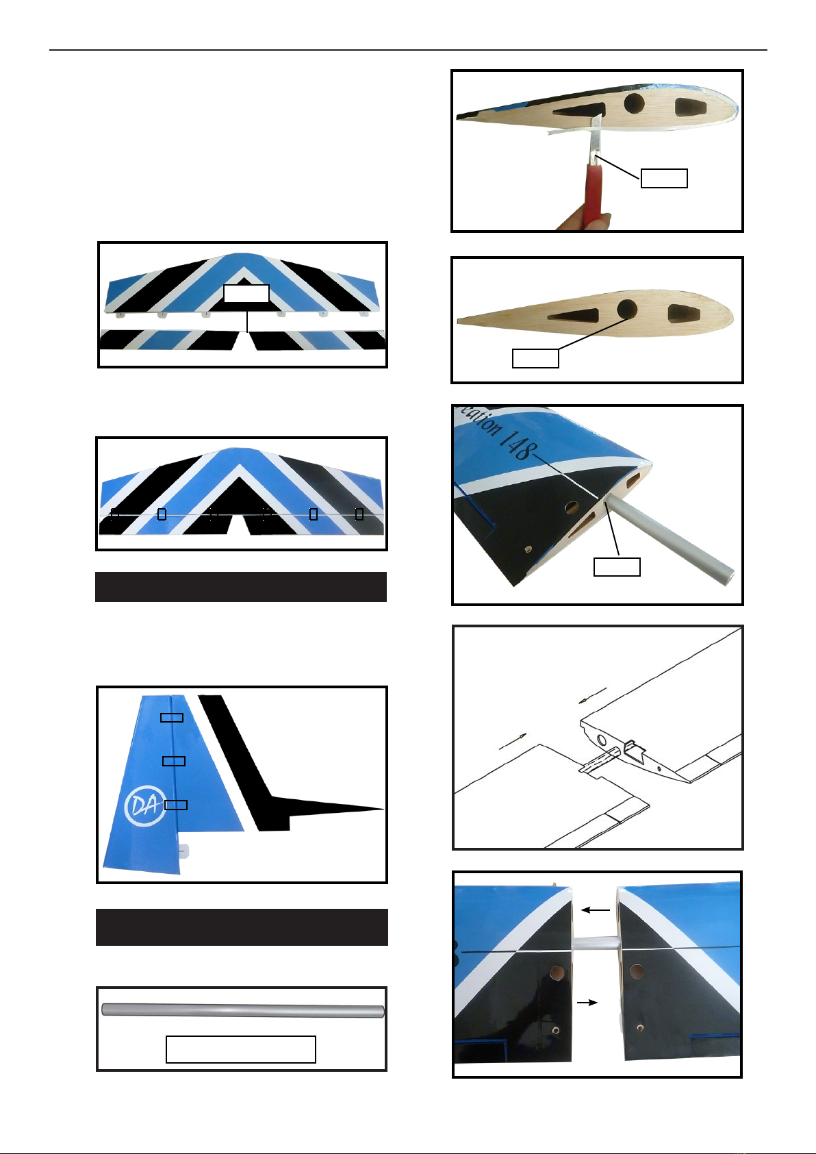
HINGING THE RUDDER.
Glue the rudder hinges in place using the
same techniques used to hinge the ailerons.
3) Remove each hinge from the horizontal
stabilizer panel and elevator and place a Tpin
in the center of each hinge. Slide each hinge
into the elevator until the T- pin is snug
against the elevator. is will help ensure an
equal amount of hinge is on either side of the
hinge line when the elevator is mounted to
the horizontal stabilizer panel.
Epoxy
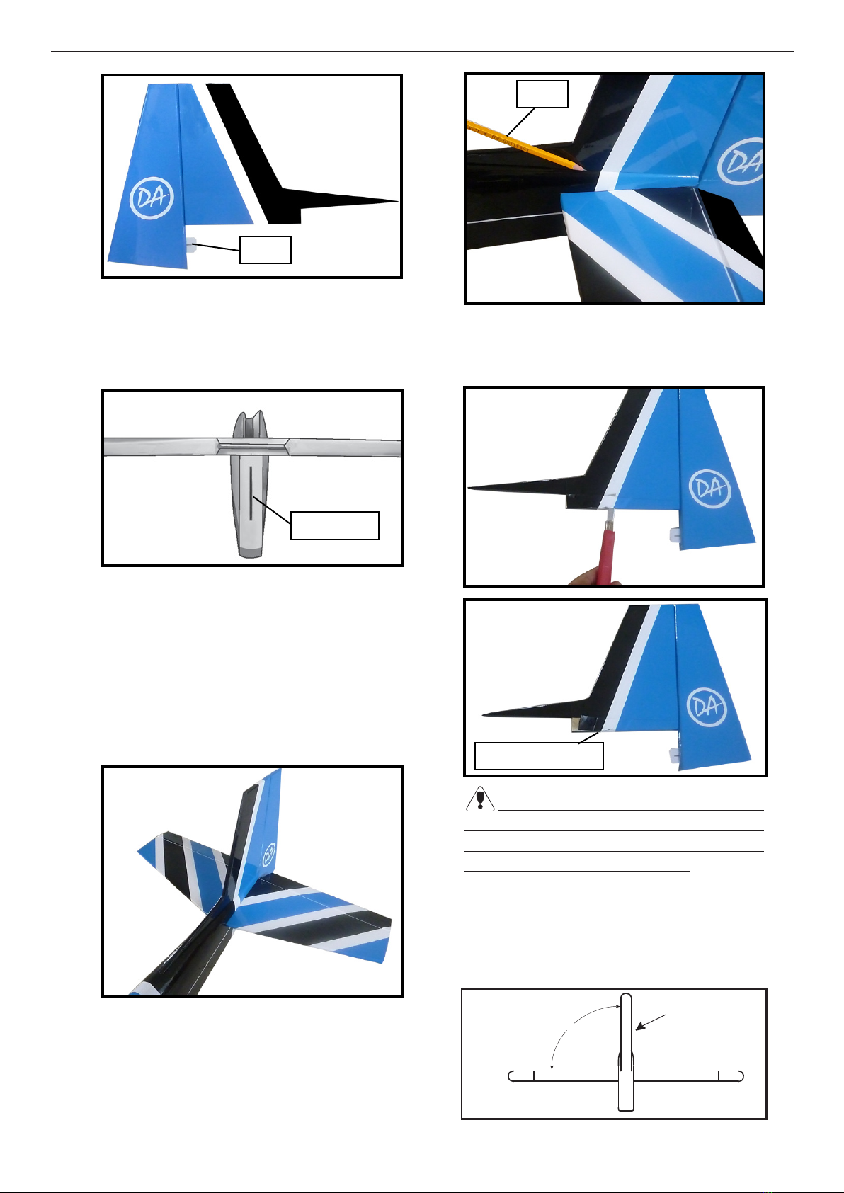
WING ASSEMBLY.
Aluminium wing tube
See below pictures :
Epoxy
Epoxy
Knife.
6
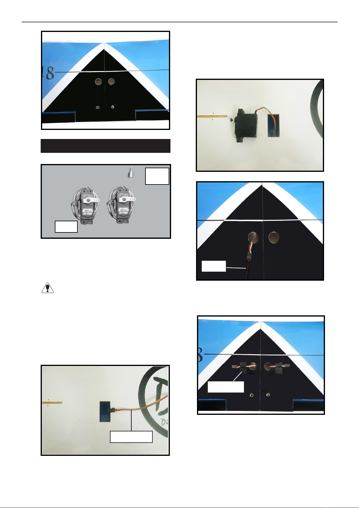
INSTALLING THE AILERON SERVO.
.
1) Install the rubber grommets and brass
collets onto the aileron servo. Test t the ser-
vo into the aileron servo mount.
Because the size of servos dier, you may
need to adjust the size of the precut openingin
the mount. e notch in the sides of the mount
allow the servo lead to pass through.
4) Tape the servo lead to the wing to prevent
it from falling back into the wing.
5) Reinstall the servo into the servo mount
and secure the servo inplace using the wood
screws provided with you radio system.
2) Using a small weight (Weighted fuel pick-
up works well) and thread, feed the string
through the wing as indicated.
3) Attach servo lead to the aileron servo. At-
tach the string to the servo lead and carefully
thread it though the wing. Once you have
thread the lead throught the wing, remove
the string so it can use for the other servo
Electric wire.
Thread.
Plastic tape.
.
.
Servos
Small
weight.
77
AILERON LINKAGE.
Repeat the procedure for the other wing
half.
1) Using a ruler & pen to draw a straight line
as below picture.
2) Locate the two nylon control horns, two
nylon control horn backplates and four ma-
chine screws.
3) Position the aileron horn on the bottom
side of aileron. e clevis attachment holes
should be positioned over the hinge line.
ControlHorn.
Mounting Screws. Mounting Plate.
7) With the aileron servo centered and the
aileron even with the trailing edge of the
wing attach the clevis to the control horn.
Mark the control wire where it crosses the
servo arm hole.
Mark point.
Pen.
Cut.
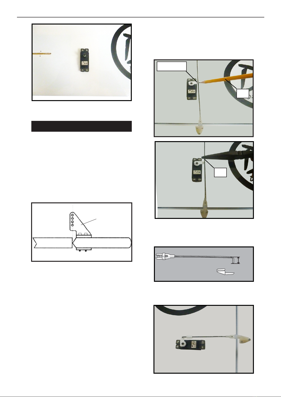
8) Make a 90-degree bend at the mark and
cut o the excess wire leaving 10mm past the
bend.
4) Using a 1mm drill bit and the control
horns as a guide, drill the mounting holes
through the aileron halves.
5) Mount the control horns by inserting the
screws through the control horn bases and
aileron halves, then into the mounting back-
plates. Do not overtighten the screws or the
backplates may crush the wood.
6) read one nylon adjustable control horn
onto each aileron control rod. read the
horns on until they are ush with the ends of
the control rods.
9) Connect the linkage as shown and secure
the control wire with a wire keeper.
8
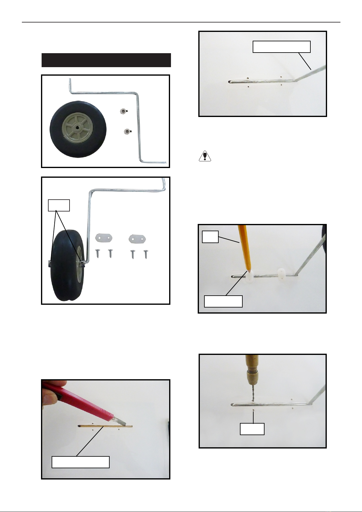
INSTALLING THE MAIN GEAR WIRES.
Be careful do not to drill through the top of
the wing !
Landing gear wire.
3) e landing gear wire is held in place us-
ing two nylon landing gear straps and four
3mm x 15mm wood screws.
e straps should be located equal dis-
tance from the inside and outside ends of the
wire.
4) Using the two landing gear straps as a
guide, mark the locations of the four 3x
10mm mounting screws onto the wing sur-
face.
Pen.
Mark point.
Collar.
Repeat the procedure for the other aileron
servos.
1) Using a modeling knife, remove the cov-
ering from over the two main gear mounting
slots located in the bottom of the wing.
2) Insert the 90º bend of one main gear wire
into the predrilled hole in one mounting
slot.
Gear mouting slot.
5) Remove the two straps and the gear wire.
Drill four 1.5mm pilot holes into the wing
for the wood screws.
1.5mm

9
Landing gear wire.
3x15 mm
6) Reinstall the gear wire and install the
straps using the four 3 x 15mm wood screws.
Tighten the screws completely to secure the
gear wire in place.
FUEL TANK. 4) Carefully heat the vent tube using a heat
gun or lighter to permanently set the angle
of the tube.
INSTALLING THE STOPPER
ASSEMBLY.
1) Using a modeling knife, carefully cut o
the rear portion of one of the two nylon tubes
leaving 1/2” protruding from the rear of the
stopper. is will be the fuel pick up tube.
2) Using a modeling knife, cut one length of
silicon fuel line (not included) to 2-1/4” long.
Connect one end of the line to the weighted
fuel pick up and the other end to the nylon
pick up tube.
3) Carefully bend the second nylon tube up
at a 45º angle. is tube is the vent tube.
When the stopper assembly is installed in
the tank, the top of the vent tube should rest
just below the top surface of the tank. It
should not touch the top of the tank.
5) Test t the stopper assembly into the tank.
It may be necessary to remove some of the
ashing around the tank opening using a
modeling knife. If ashing is present, make
sure none falls into the tank.
6) With the stopper assembly in place, the
weighted pick up should rest about 3/8” away
from the rear of the tank and move freely in-
side the tank. e top of the vent tube should
rest just below the top of the tank. It should
not touch the top of the tank.
7) When satised with the alignment of the
stopper assembly tighten the 3mm x 20mm
machine screw until the rubber stopper ex-
pands and seals the tank opening. Do not
overtighten the assembly as this could cause
the tank to split.
A
B

10
Using a modeling knife, cut one length of
fuel line 20” long. Connect one line to the
vent tube and one line to the fuel pick up
tube on the stopper. See picture bellow.
Blow through the tubes to make sure the
lines have not become kinked during installa-
tion.
Vent tube.
Fuel pick up tube.
Fuel ll tube.
INSTALLING THE SWITCH.
1) Install the switch into the precut hole in
the fuselage side. Use the two screws provid-
ed with the switch to secure it in place.
C/A glue
A
Fuel tank.
B
1111
3) When you are satised with the alignment,
mark the locations of the engine mounting.
4) Remove the engine. Using an drill bit,
drill the mounting holes through the engine
mount at the four locations marked.
MOUNTING THE ENGINE.
1) Install the pushrod housing through the
predrilled hole in the rewall and into the
servo compartment. e pushrod housing
should protrude 1/4” out past the front of
the rewall.
Make a Z-Bend 1/4” from one end of the
plain wire pushrod.
2) Place your engine onto the engine mount.
Adjust the engine is centered of the edges of
the engine case.
115 mm
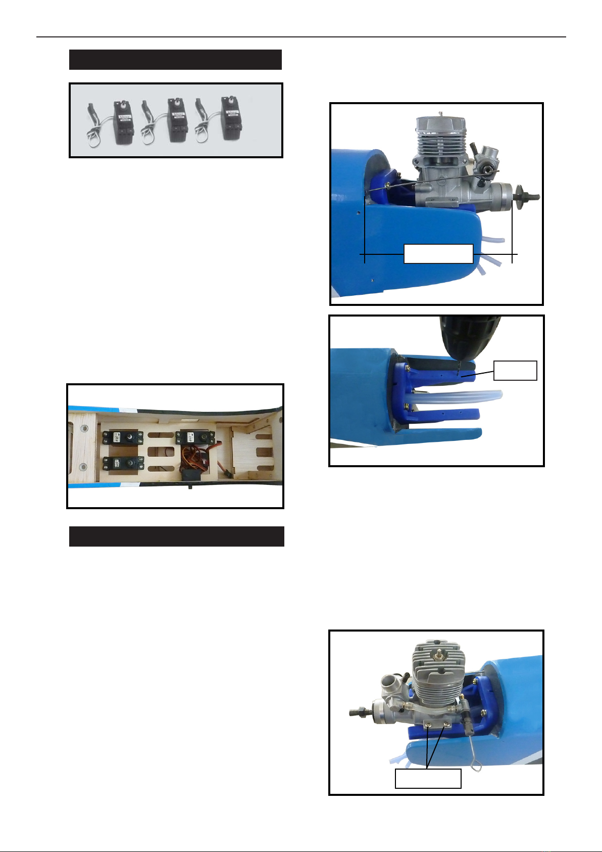
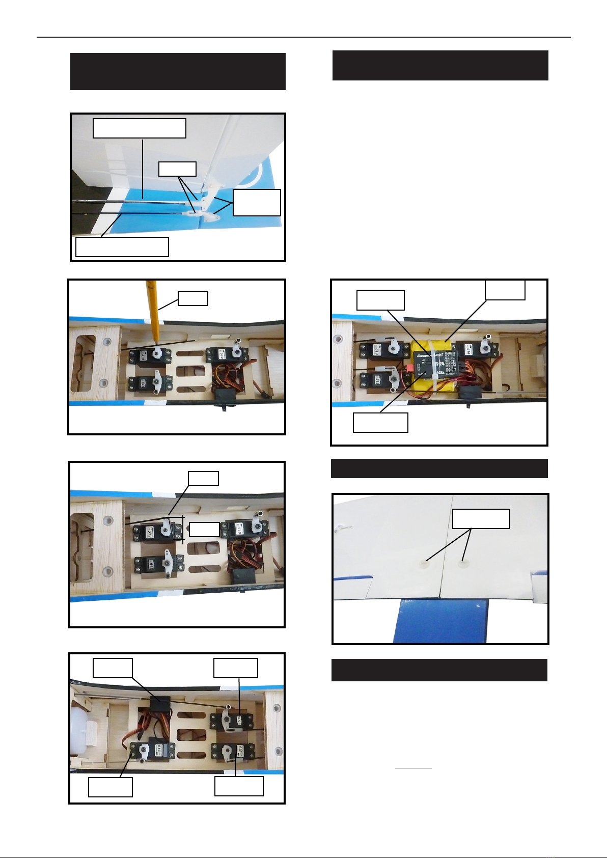
INSTALLING THE FUSELAGE SERVOS.
1) Install the rubber grommets and brass
collets onto the elevator, rudder and throttle
servos. Test t the servos into the prein-
stalled servo tray. Because the size of servos
dier, you may need to adjust the size of the
precut openings in the tray.
Secure the servos with the screws provided
from your radio system.
2) Position the servos into the servo tray with
the output shas orientated as shown below.
Drill 1/16” pilot holes through the tray for
each of the mounting screws.
5) Bolt the engine to the engine mount using
the four machine screws. Double check that
all the screws are tight before proceeding.
6) Attach the Z-Bend in the pushrod wire to
the throttle arm on the carburetor. You will
need to remove the throttle arm from the
car- buretor to be able to attach the Z-bend.
When complete, re-attach the throttle arm to
the carburetor.
1.5 mm
3x25 mm
12 12
Pushrod wire.
.
NOSE GEAR INSTALLATION.
Installing steering arm as below.
13
ELECTRIC POWER CONVERSION.
1) Locate the items neccessary to install the
electric power conversion included with
your model.
- Model size: .46 size models
- Motor: 35mm 830 rev per volt
- Propeller: 13x 6
- ESC: 50A
- Lipo Batteries: 4cell 4200mA
3mm
INSTALLING THE SPINNER.
Install the spinner backplate, propeller and
spinner cone. e spinner cone is held in
place using two 3 x 15mm wood screws.
e propeller should not touch any part
of the spinner cone. If it does, use a sharp mod-
eling knife and carefully trim away the spinner
cone where the propeller comes in contact with
it.

14
4mm
4mm
Blind nut
M4x70 mm
3x12mm

15
Battery.
Speed control.
COWLING
1) Slide the berglass cowl over the motor
and line up the back edge of the cowl with
the marks you made on the fuselage then
trim and cut as shown.
2) While keeping the back edge of the cowl
ush with the marks, align the front of the
cowl with the cranksha of the engine. e
front of the cowl should be positioned so the
cranksha is in nearly the middle of the cowl
opening. Use the spinner backplate as a
guide. Hold the cowl rmly in place using
pieces of masking tape.
16
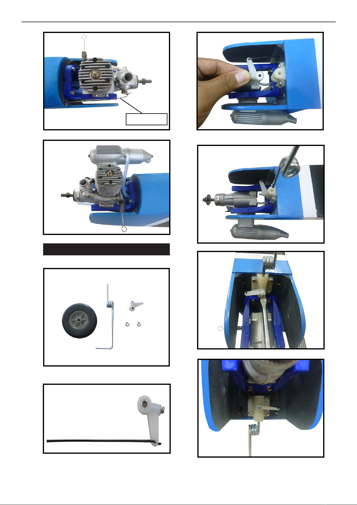
HORIZONTAL STABILIZER.
1) Using a ruler and a pen, locate the center-
line of the horizontal stabilizer, at the trailing
edge, and place a mark. Use a triangle and
extend this mark, from back to front, across
the top of the stabilizer. Also extend this
mark down the back of the trailing edge of
the stabilizer.
3x10mm
3) Install the muer and muer extension
onto the engine and make the cutout in the
cowl for muer clearance. Connect the fuel
and pressure lines to the carburetor, muer
and fuel ller valve. Secure the cowl to fuse-
lage using the M3x10mm screws.
2) Using a modeling knife, carefully remove
the covering from over the vertical stabilizer
mounting slot in the top of the fuselage.
3) Slide the stabilizer into place in the precut
slot in the rear of the fuselage. e stabilizer
should be pushed rmly against the front of
the slot.
Center line.
INSTALLING THE SPINNER.
Install the spinner backplate, propeller and
spinner cone. e spinner cone is held in
place using two 3 x 15mm wood screws.
e propeller should not touch any part
of the spinner cone. If it does, use a sharp
modeling knife and carefully trim away the
spinner cone where the propeller comes in
contact with it.
17
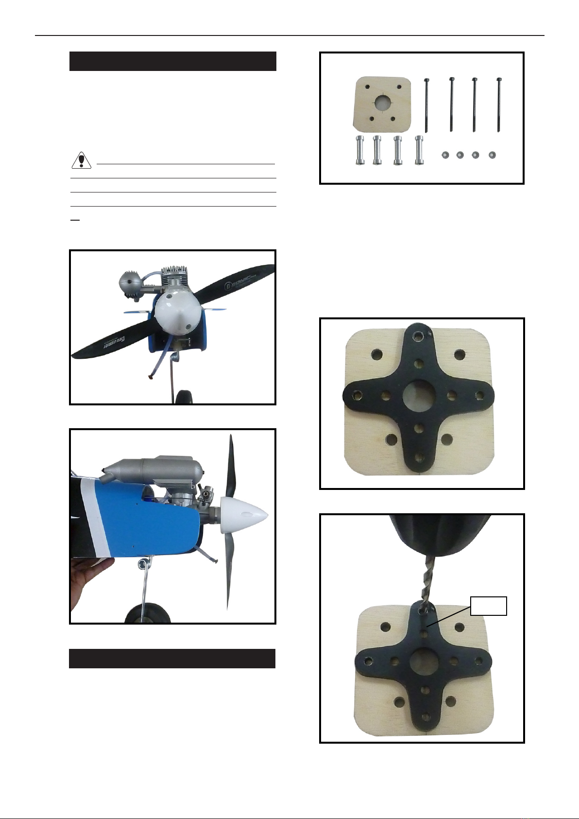
4) With the stabilizer held rmly in place,
use a pen and draw lines onto the stabilizer
where it and the fuselage sides meet. Do this
on both the right and le sides and top and
bottom of the stabilizer.
5) Remove the stabilizer. Using the lines you
just drew as a guide, carefully remove the
covering from between them using a mod-
eling knife.
Pen.
When cutting through the covering to re-
move it, cut with only enough pressure to only
cut through the covering itself. Cutting into
the balsa structure may weaken it.
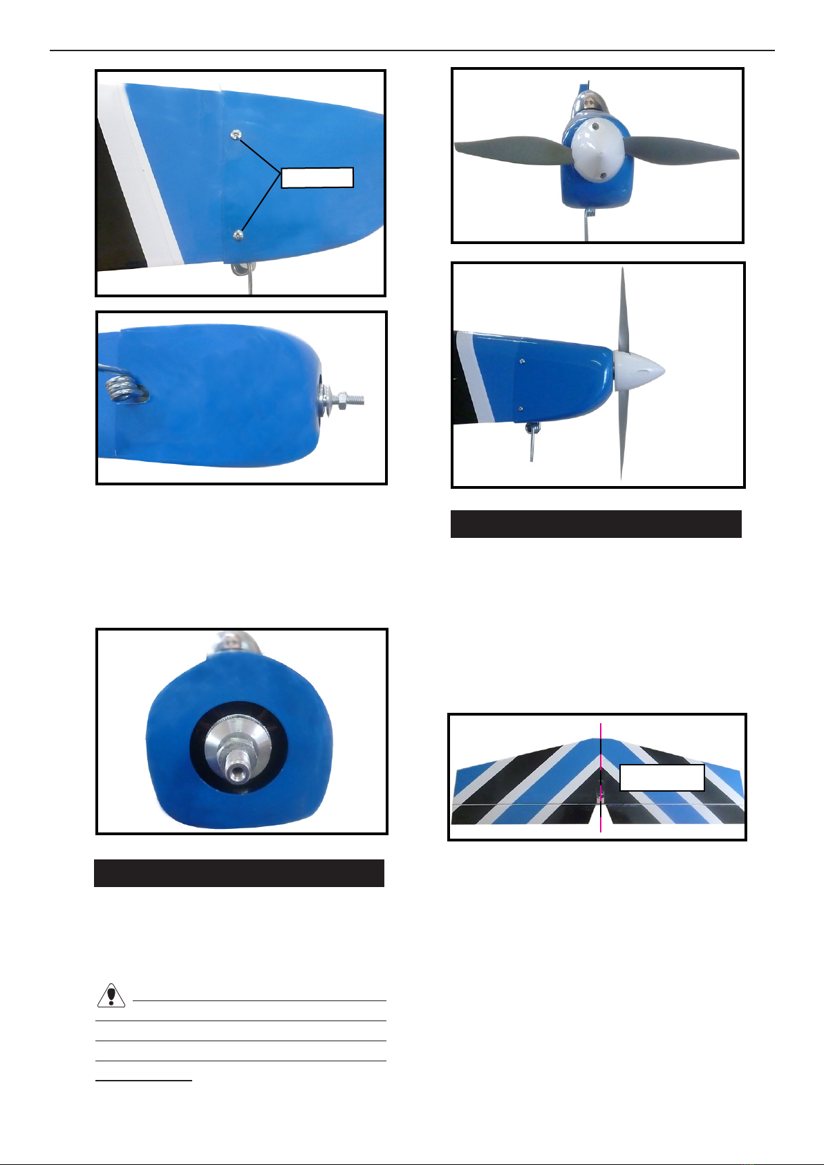
6) Using a modeling knife, carefully remove
the covering that overlaps the stabilizer
mounting platform sides in the fuselage. Re-
move the covering from both the top and the
bottom of the platform sides.
Remove covering.
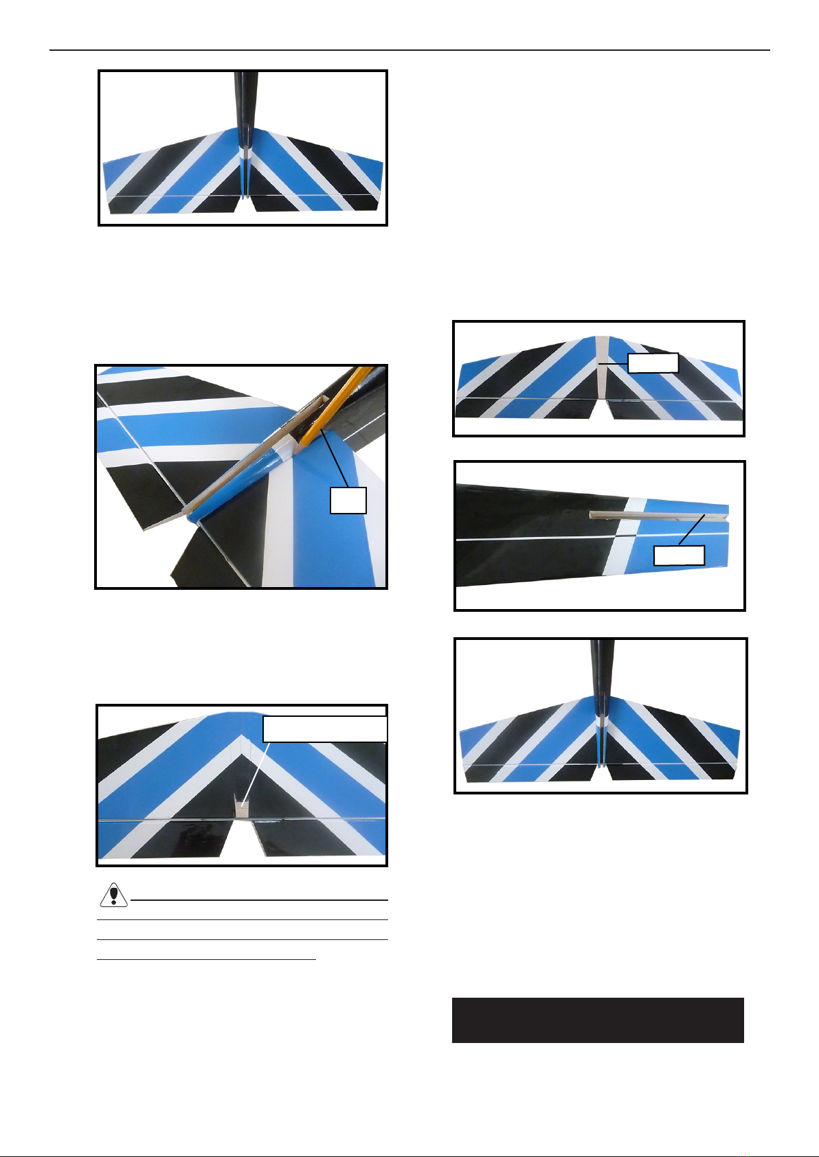
7) When you are sure that everything is
aligned correctly, mix up a generous amount
of 30 Minute Epoxy. Apply a thin layer to the
top and bottom of the stabilizer mounting
area and to the stabilizer mounting platform
sidesin the fuselage. Slide the stabilizer in
place and realign. Double check all of your
measurements once more before the epoxy
cures. Hold the stabilizer in place with T-
pins or masking tape and remove any excess
epoxy using a paper towel and rubbing al-
cohol.
8) Aer the epoxy has fully cured, remove
the masking tape or T-pins used to hold the
stabilizer in place. Carefully inspect the glue
joints. Use more epoxy to ll in any gaps that
may exist that were not lled previously and
clean up the excess using a paper towel and
rubbing alcohol.
VERTICAL STABILIZER
INSTALLATION.
Epoxy
Epoxy
18
1) Using a modeling knife, remove the cov-
ering from over the precut hinge slot cut into
the lower rear portion of the fuselage. is
slot accepts the lower rudder hinge.
2) Slide the vertical stabilizer into the slot in
the top of the fuselage. e rear edge of the
stabilizer should be ush with the rear edge
of the fuselage and the lower rudder hinge
should engage the precut hinge slot in the
lower fuselage. e bottom edge of the stabi-
lizer should also be rmly pushed against the
top of the horizontal stabilizer.
3) While holding the vertical stabilizer rm-
ly in place, use a pen and draw a line on each
side of the vertical stabilizer where it meets
the top of the fuselage.
4) Remove the stabilizer. Using a modeling
knife, remove the covering from below the
lines you drew.
When cutting through the covering to re-
move it, cut with only enough pressure to only
cut through the covering itself. Cutting into
the balsa structure may weaken it.
5) Slide the vertical stabilizer back in place.
Using a triangle, check to ensure that the ver-
tical stabilizer is aligned 90º to the horizontal
stabilizer.
90º
Vertical
Stabilizer.
Horizontal
Stabilizer.
Hinge.
Pen.
Hinge slot.
Remove covering.
1919
Epoxy
6) When you are sure that everything is
aligned correctly, mix up a generous amount
of 30 Minute Epoxy. Apply a thin layer to
the mounting slot in the top of the fuselage
and to the sides and bottom of the vertical
stabilizer mounting area. Apply epoxy to the
bottom and top edges of the ller block and
to the lower hinge also. Set the stabilizer in
place and realign. Double check all of your
measurements once more before the epoxy
cures. Hold the stabilizer in place with T-
pins or masking tape and remove any excess
epoxy using a paper towel and rubbing al-
cohol. Allow the epoxy to fully cure before
proceeding.
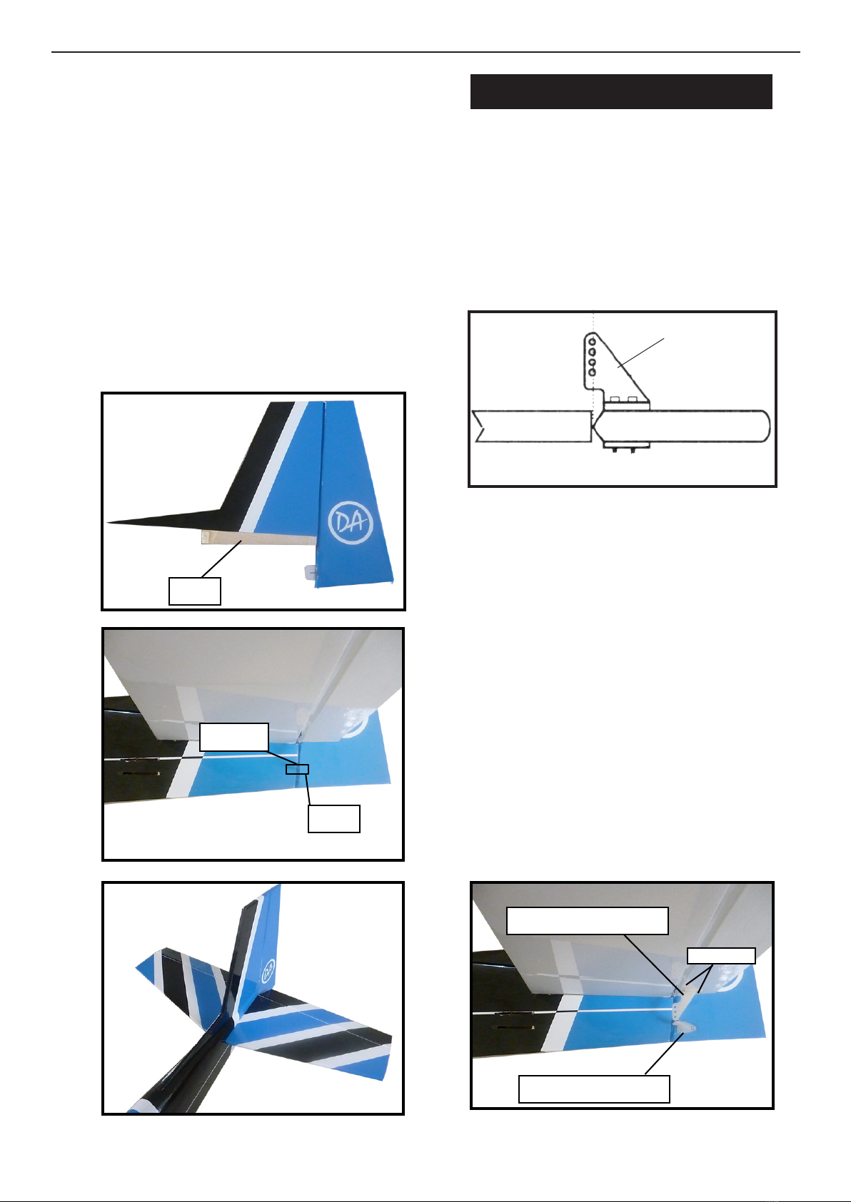
CONTROL HORN INSTALLATION.
1) Locate the nylon control horns- nylon
control horn backplates and machine screws.
2)e position of elevator control horn on
the le side of elevator. e clevis attach-
ment holes should be positioned over the
hinge line.
ControlHorn.
Mounting Screws. Mounting Plate.
3) Using a 2mm drill bit and the control
horns as a guide, drill the mounting holes
through the elevator halves.
4) Mount the control horns then into the
mounting backplates. Do not overtighten the
screws or the backplates may crush the wood.
5) Position the rudder control horn on the
le side of the airplane.
6) Install the rudder control horn using the
same method as with the elevator control
horns.
Elevator control horn.
Rudder control horn.
2x15mm
Hinge.
C/A glue.
2020
INSTALLING THE RECEIVER AND
BATTERY.
1) Plug the ve servo leads and the switch
lead into the receiver. Plug the battery pack-
lead into the switch also.
2) Wrap the receiver and battery pack in the
protective foam rubber to protect them from
vibration.
3) Route the antenna out of the fuselage and
secure it to the vertical stabilizer using a rub-
ber band and a modied servo arm. See pic-
ture as below.
ATTACHMENT WING- FUSELAGE.
.
BALANCING.
1) It is critical that your airplane be bal-
anced correctly. Improper balance will
cause your plane to lose control and
crash. THE CENTER OF GRAVITY IS
LOCATED 72MM BACK FROM THE
LEADING EDGE OF THE WING AT
THE WING ROOT.
Switch.
Throttle.
Rudder.
Elevator.
.
Battery.
Tie wrap.
Receiver.
ELEVATOR - RUDDER PUSHROD IN-
STALLATION.
Elevator pushrod.
Rudder pushrod.
Control
horn.
Clevis.
Wing Bolt
Pen.
8mm
Cut.
This manual suits for next models
2
Table of contents
Other Direct Airscale Toy manuals


Popular Toy manuals by other brands


Fisher-Price
Fisher-Price BARBIE Sport Mobile 74558 Owner's manual & assembly instructions

Tamiya
Tamiya BLACKFOOT XTREME owner's manual

Seagull Models
Seagull Models SEA FURY Assembly manual

PIKO
PIKO BR V60-TT Instructions for use

GRAUPNER
GRAUPNER JetCat 6810 manual

Kids II
Kids II Oball GoGrippers Adventure Park Playset manual