Merlin CESSNA T-206 User manual

INSTRUCTION MANUAL
ML45015
English - 1-13
Deutsch - 14-27
Français - 28-41
Español - 42-55

We know you will have great fun with your model, but to get the best from your purchase please read
this information BEFORE you operate the model
Table of contents
Page
Warranty ………………………………………………………..….. 1
90 Day omponent Warranty………………………………… 1
Not covered by warranty………………………………………. 1
How to claim against your warranty………………………….. 1
Introduction………………………………………………………… 2
Specifications…………………………………………………… 2
Items required for operation…………………………………… 2
Glossary…………………………………………………………. 2
Safety precautions…………………………….………………. 3
Recommended tools…………………………………………… 3
harging the battery pack…………………………………….. 3
Transmitter………………………………………………………… 4
Preparing the transmitter……………………………………… 4
Throttle stick…………………………………………………….. 4
Elevator stick……………………………………………………. 4
Rudder stick…………………………………………………….. 4
Aileron Stick…………………………………………………….. 4
Assembly Guide………………………………………………….. 5
Trimming Adjustments and Control Test……...……. 7
Making trim adjustments to the horizontal stabiliser & rudder 7
Motor test………………………………………………………… 7
Flight Controls ……………………..……………………. 8
Using the Motor……………………..…………………………. 8
Using the Elevator……………………………………………… 8
Using the Ailerons……………….…….……………………….. 8
Using the Rudder….……………….….……………………….. 8
Pre flight Checklist and Control Test……………………. 9
hecklist…………………………………………………………. 9
ontrol test………………………………………………………. 9
Range test……………………………………………………….. 9
How to Fly……………………………………………………………. 10
Experience……………………………………………………….. 10
Site and conditions………………………………………………. 10
Taking off…………………………………………………………. 10
Turning and flying………………………………………………... 10
Landing……………………………………………………………. 11
Tips for success………………………………………………….. 11
Helpful Information..………….…………………………………. 12
Trouble shooting……………...…………………………………. 12
Parts listing….………………………………………………… … 12
Repairing minor damage……………………………………….. 13
Receiver and servo wiring….………..…………………………. 13
Transmitter additional functions……………………………….. 13
Notes…………………………………………………. …………. 13
HAVE FUN! But please read this first !!

1
Warranty
90 Day Component Warranty
We want you to enjoy your Merlin Flight Product, but please read this first!
This product is covered by a 90 day co ponent warranty fro date of purchase. If any part of the product fails as a
result of faulty anufacture during this period then we will repair or replace that part at our discretion.
We do not operate a new for old warranty once the product has been used.
Please note this product is not a toy and it is reco ended that children 14 and under are supervised by an adult. It
is the responsibility of the parent or guardian to ensure inors are given appropriate guidance and supervision.
If you suspect there is a proble with the product, for whatever reason, it is the user’s responsibility to investigate
and take steps to rectify the proble before further da age occurs.
Not Covered By Warranty
This is a sophisticated, high perfor ance odel and should be treated with care and respect. Every effort has been
ade to ake this product as strong and durable as possible, however due to the nature of this product, it is still
possible to break or da age parts through crashing or extre e use. Co ponents da aged as a result of crash
da age, i proper use, lack of aintenance or abuse are not covered by the warranty.
How to Claim Against your Warranty
For warranty clai s please first contact your supplying retailer. Do not return the product to your distributor without
their prior approval. You ay not need to return the product in full, only the da aged co ponent along with a copy
of your purchase receipt. In any cases it is faster and ore cost effective for the user to fit the replace ent part(s)
to the product & therefore we reserve the right to supply parts only in these instances.
Any returned co ponent that is inspected by your distributor and found to have an invalid warranty clai ay be
subject to an inspection and handling fee before it can be returned. Any repairs required as a result of neglect or is-
use will be charged before any work is carried out on the product. If you decide not to have any work carried out the
distributor reserves the right to charge a handling and a shipping fee. The level of these fees are at the discretion of
the distributor.
Please attach your proof of purchase in the anual as you ay need it again in the future.

Items required for operation
8 * AA Batteries for the Trans itter
Glossary
Ailerons - Rolls the aeroplane and/or provides directional control
Landing gear - Wheels on botto of aeroplane
Vertical fin - Fin on back of aeroplane
Rudder - Moveable fin on vertical fin
Elevator - Moveable fins of the stabiliser
Fuselage - Main body of the aircraft containing otor, receiver, speed control, servos and battery
Stabiliser - S aller flat wing on tail of aircraft
2
pecifications
Wingspan 1080
Fuselage Length 965
Flying Weight 610g
Motor Brushless Out runner Motor 1300Kv
Battery 7.4v 2 Cell 1700 ah 10C Li-Poly er Battery
Flight Ti e Approx 15 inutes
Trans itter MTX-42 35 MHz 4 Channel
Receiver MRX-42 35 MHz 6 Channel
Charger 12v/240v Balancing Battery Charger
Servos 3 x 9g Servo
Speed Control 20A Brushless ESC
Introduction

3
afety Precautions
• Read and follow this anual co pletely, observing all instructions and safety directions. Otherwise, serious
injury and da age can occur. Think about your safety, and the safety of others, first.
• Hold the aeroplane securely when the flight battery is plugged in, keep the propeller away fro body parts
and clothing, even when it isn’t spinning, as it could be turned on by accident. Beware of hair beco ing en
tangled in the propeller, especially while launching your aeroplane.
• Do not fly when it’s too windy or you ay lose control and crash, causing injury or da age. Never fly near
people, vehicles, train tracks, buildings, power lines, water, hard surfaces or trees. Never allow anyone to
atte pt to catch the aeroplane while it’s in flight or serious injury ay result.
• Adult supervision for flying and battery charging is reco ended for pilots age 14 and younger.
• Only use a battery charger that is Li-Po co patible to charge the flight battery. Never leave the charger
unattended while charging. This will help prevent overcharging and ake sure da age does not occur to the
battery, charger or any other property. While charging, place the battery on a heat-resistant surface. Do not lay
it on carpet or upholstery while charging.
• Never cut into the battery, charger, or aeroplane wires or serious injury ay occur. Causing the battery to
“short out” (crossing negative and positive bare wires) can cause fire, serious injury and da age.
• When you finish flying your aeroplane, always unplug the battery before you turn off the trans itter.
• Never fly on the sa e frequency as another RC aeroplane in your area. The frequency of the aeroplane is
shown on the frequency crystals.
Recommended Tools
These tools are not included with the product but are reco ended for use whilst working with this product
Mini Philips Screwdriver Foa Safe Super Glue
Charging the battery pack
Use the supplied charger to charge the supplied battery. Other products are available and if used, you ust follow
the products instructions to avoid da age.
The charge ti e for the battery is 130 inutes.
1. Connect the 240V wall ounted transfor er (12V output) to the input side of the supplied charger, the red
power indicator should glow.
2. Plug the aeroplane battery into the 7.4V 2-cell output socket of the charger. The charge indicator should glow
green after 5 seconds to indicate charging is taking place.
3. When charging is co plete the charger will auto atically stop charging and the green light will go out.
4. Unplug the battery and input to the charger.
If the charge indicator does not glow green when the battery is plugged in or flashes then the battery is already fully
charged. For flying field use a 12V lead input is provided which can be connected to an auto otive car battery ensur-
ing the correct polarity is used. Red = positive ter inal, black = negative ter inal
Cautions
• Use the charger with adult supervision. Do not use the charger near water or when wet.
• Do not use the charger if the wire is frayed or worn. If the wire is frayed or worn a short circuit can cause a fire
or burns.
• If your battery gets hot and exceeds 50 degrees C during charge it ay be faulty and should be replaced.
• If the battery pack bulges during charge or use it is faulty and should be replaced.
• Never leave your battery on charge unattended.
Packing Tape

Preparing the transmitter
4
Insert the aerial into the
hole and turn clockwise
until it is tightly secured.
Make sure you never over
extend the aerial as this
will cause it to break.
Open the battery hold-
ing tray to expose the
e pty battery slots.
Insert 8 AA batteries
into the arked spaces.
Please note the correct
direction of the batteries
Throttle tick
Rudder tick
9
10 11
12
1
4
7
2
3
5 6
8
13
16
15
14
Elevator tick
1. Push the stick
forward to increase
propeller speed
2. Pull the stick
backwards to
decrease propeller
speed
1
2
1
2
1 2
1. Push the stick left to roll left,
left hand elevator oves up
and right side down
2. Push the stick right to roll
right, left hand elevator
oves down and right side
up
1. Push the stick forward to
lower the nose,
elevator oves down
2. Pull the stick backwards
to raise the nose,
elevator oves up
1. Push the stick left to
turn left, rudder
oves left
2. Push the stick right
to turn right, rudder
oves right
Aileron tick
1 2
1. Aerial
2. Throttle Tri
3. Aileron Tri
4. Elevator Tri
5. Throttle/Rudder Stick
6. Aileron/Elevator Stick
7. Power Switch
8. Battery level indicator
9. Rudder reverse switch
10. Aileron reverse switch
11. Throttle reverse switch
12. Elevator reverse switch
13. Frequency Crystal
14. Rate Switch (see page 13)
15. Aileron/Elevator Mixer
Switch (see page 13)
16. Rudder Tri
Transmitter
The Merlin Trans itter is an advanced controller designed for the beginner to be easy to use and tune. You will need
to follow the steps below to ensure you prepare the controller correctly for use and understand the adjust ent possi-
bilities available.

5
Please ake sure you group the
screws into the above 4 groups
Insert the undercarriage into the
section of the fuselage as shown.
Use screws B to fasten.
Insert tail into ain fuselage as
shown. Use screws D to fasten.
Insert the rudder in to the fuselage
openings.
1 2
3 4
Assembly Guide

6
Attach the clevises on the tail and
rudder, insert into the iddle hole.
Check tri ing section for further
infor ation
Connect the servo for the wing with the
lead in the fuselage. Then place the wing
securely in place and use screws A to
fasten. Plug the lead fro the servo into
channel 2 on the receiver.
Insert the nose cone onto the ain
propeller shaft.
Attach the wing struts to the
fuselage and wings. Use screws C
to fasten.
5 6
8

7
Making Trim Adjustments to the Horizontal tabiliser & Rudder
1. Make sure the throttle stick is in the “off” position by pulling it fully back.
2. Turn on the trans itter and check the LED power lights co e on.
3. Set the aileron, elevator & rudder tri levers to the centre.
4. Install a fully charged battery into the battery co part ent nearest the front of the aeroplane and plug in the
connector to switch on.
5. The control surfaces should ove as the control sticks are oved.
6. Make certain the elevator is set to neutral and is flat with the horizontal stabiliser. Do this by re oving the
clevis fro the control horn and turning it on the threaded pushrod as needed. Once the adjust ent is ade,
re-attach the clevis.
7. Make certain the rudder is set to neutral and is flat with the tail fin. Do this by re oving the clevis fro the
control horn and turning it on the threaded pushrod as needed. Once the adjust ent is ade, re-attach the
clevis.
8. Make certain the ailerons when set to neutral are flat with the wing. Do this by re oving the clevis fro the
control horn and turning it on the threaded pushrod as needed. Once the adjust ent is ade, re-attach the
clevis.
9. If for any reason the controls ove in opposite directions to those explained in the trans itter functioning then
change the position of the relevant reverse switch on the trans itter.
1
6 & 8
6 & 8 4
It is i portant that the control surfaces of your aeroplane are correctly set for it to fly correctly.
Warning: Keep everything clear of the propeller before starting the tests so you do not da age any property or har
anyone.
Motor Test
With the trans itter and aeroplane already switched on fro above
1. Hold the aeroplane fir ly by its fuselage and keep everything clear of the propeller.
2. Push the throttle stick forwards slowly and the propeller should spin at speed.
3. When finished with the otor test, disconnect the battery and then turn off the trans itter. Follow this step
each ti e you need to turn the aeroplane off.
4. If for any reason the otor operates on full power with the control stick pulled backwards and is off in the
forward position then switch off the power and reverse the relevant reverse switch on the trans itter. Then
re-test as above.
Trimming Adjustments & Control Tests

8
Using the Ailerons
In a 4-channel odel the ailerons provide the pri ary control for turning.
• Moving the stick to the left or right will roll the aeroplane which will begin to turn and slip sideways.
• To continue the turn the aileron is returned to neutral and up elevator applied until the desired direction is
achieved.
• To co plete the turn an opposite application of aileron will achieve level flight.
• Continued holding of the aileron stick will cause the aeroplane to roll upside down and eventually level once
ore, such as used in advanced aerobatic anoeuvres.
Using the Motor
The otor is used to control the flying speed and rate of cli b of the aeroplane
• Initial take off and cli b to ini u altitude is carried out at full power.
• To achieve and aintain a level “cruising” altitude, reduce the power by oving the throttle stick down to
approxi ately 70% of full on. The throttle stick is proportional, so you can add or reduce throttle in s all
incre ents as needed to aintain the altitude that you desire.
• To reduce altitude you need to reduce the throttle, and to increase altitude you need to increase the throttle
Using the Elevator
The elevator is used to control the pitch (level) of the aeroplane. In nor al flight s all adjust ents of the elevator are
used to aintain even level flight.
• Pushing forwards on the elevator stick akes the nose lower and the speed to increase entering a dive.
• Pulling back on the stick provides up elevator aking the nose rise and flight speed slow. Pulling too far back
on the elevator and cli bing too quickly will cause the aeroplane stall. To avoid crashing fro a stall, always
aintain enough altitude to recover. Just after a stall has occurred, the nose of the aeroplane will fall and the
aeroplane will look like it is diving. To pull out of a stall, si ply pull back slowly on the elevator stick until level
flight is resu ed. Pulling back too quickly or for too long will once again cause the aeroplane to enter a stall.
Using the Rudder
The rudder is used to control the turning of your aeroplane in the air or when taxiing on the ground through the
steerable front nose wheel. Once airborne on a 4-channel odel the rudder is used to help with aileron turns or for
ore co plex aerobatic anoeuvres.
Flight Controls

9
Checklist
• Control surfaces have free ove ent
• All screws, bolts, etc. are tight
• Radio equip ent is securely fastened inside fuselage
• Batteries are fully charged
• No wires interfere with servo otors
• Antenna is properly strung
• Wings are securely fastened
• Looking fro the rear of the aeroplane to the front ake sure that the wings and tail are not da aged and
are correctly aligned to the fuselage.
Control Test
Warning: Keep everything clear of the propeller before starting the control test in the event that you accidentally turn
on the otor.
1. Be certain that the throttle stick is in the “off” position and that both tri levers are centred.
2. Switch on the trans itter and check to ake sure the red LED is lit continuously, indicating the trans itter
has power. If the red LED is flashing then the trans itter batteries are low on power and ust be replaced
before flying.
3. Install the flight battery into the fuselage and plug it into the battery connector
4. Move the trans itter control sticks. The control surfaces should ove as per your trans itter input.
5. Move the throttle stick forwards, the propeller should spin.
Each ti e before you start flying your Merlin Flight Product please carry out the following check checks and test.
Pre-Flight Checklist and Control Test
Range Test
1. Leave the aeroplane and walk 100 paces away whilst checking the control functions are still working.
2. If you can see or hear the control functions are still working then the range test is co plete.
3. If the control functions do not work to your co ands at 100 paces, do not atte pt to fly your aeroplane and
refer instead to the troubleshooting section of this anual.

10
How to Fly
Experience
A pilot who has never flown an aeroplane at all will find it easier if an experienced radio control pilot is present to
guide the but by carefully following the anual’s basic instructions, flying skills can be learnt and astered.
ite and Conditions
• Don’t fly in winds over 8 ph! If you are a less experienced pilot, this is especially i portant.
• Choose your flying field carefully - grass and soft ground with a 150- etres dia eter of open space is ideal.
Make sure there are no obstacles that will get in your way when flying, such as trees or buildings. Make sure
you do not fly where there are pedestrians who could be hurt by the aeroplane.
• Position yourself at your flying field so that you keep the sun at your back and out of your eyes. Wear
sunglasses on bright days.
• Keep your aeroplane in front of you so you don’t have to turn in circles as you fly. Try to avoid flying directly
overhead.
• Keep the aircraft upwind, especially on windier days, to prevent it fro “flying away”
Turning and Flying
1. Before your aeroplane beco es too distant begin turning by oving and releasing the aileron stick gently until
the wings are at an angle of 30 degrees. Then pull back on the elevator to tighten the turn & achieve the de-
sired direction. Gently apply opposite aileron to achieve level flight.
2. Avoid holding the aileron stick on full right or full left for ore than one second, as this will cause the aeroplane
to enter a spiral dive that could cause you to crash.
3. Once a nor al flight altitude of 15-50 etres has been achieved reduce the throttle stick to 50-75 % of full
power. This will prevent your aeroplane cli bing further, ake it easier to control and lengthen the flight ti e.
4. Practice control by turning in large circles.
5. To ake your aeroplane descend reduce the throttle stick to 0-25 % of full power and it will enter a glide. A
s all a ount of up elevator ay be needed to keep the plane level and prevent it gaining too uch speed.
Taking Off
Your Merlin aeroplane can take off fro a s ooth ground however we reco end first flights to be hand launched.
This can be carried out by the pilot alone but is easier with two people, one launching the aeroplane and the other at
the controls.
1. While holding the trans itter in one hand, push throttle stick to full on (up).
2. Hold your aeroplane with your other hand, take a couple of steps and fir ly launch directly into the wind while
keeping the wings level. Do not throw it up or down. Point it level (parallel) with the ground when releasing.
3. Keep steering into the wind and hold at full throttle in a slight cli b Do not try to cli b too fast by pulling all the
way back on the elevator stick or your aeroplane ay stall. You should cli b by giving s all a ounts of ele-
vator.
4. When you have reached an altitude of at least 15 to 20 etres it is safe to steer in the desired direction, as
well as adjust the throttle input, to help control altitude and speed.

11
Landing
When you begin to notice that your Merlin Product no longer cli bs well under full power the battery is getting low
and it is ti e to land.
1. Bring your aircraft directly into the wind and toward the desired landing spot.
2. Gradually reduce throttle (and give a s all a ount of down elevator if you choose) to reach an altitude of
approxi ately 3 etres.
3. At this point, reduce the throttle to zero and your aeroplane should glide in softly for a landing.
Tips for uccess
• The flight of your aeroplane ay change as you enter into or fly with the wind causing the nose to rise or fall,
especially in ore windy conditions. To aintain a ore controlled flight be prepared to adjust the elevator
control to keep the nose of the aeroplane level whilst turning.
• If your aeroplane continues to turn left or right with the control stick in neutral position, you can apply a s all
a ount of opposite tri by oving the appropriate tri lever whilst still in flight.
• If when gliding your aeroplane or on low power settings it continues to dive, then adjust the tri lever on the
elevator backwards to obtain level flight.
• If when gliding your aeroplane or on low power settings it continues to stall, then adjust the tri lever on the
elevator forwards to obtain level flight.
• Note that the control range is 750 etres. Do not allow the aeroplane to get too far away fro you. When the
aeroplane is further away it is harder to see and the higher you fly, the ore the aeroplane will be affected by
wind.
• If you’re gliding with the otor off, allow your aeroplane ore area for turns.
• Re e ber that holding the stick full over for too long can cause the aeroplane to spiral dive and crash. At the
very first sign of the aeroplane beginning to spiral down, i ediately release the stick and give the opposite
turn control to the spiral, then pull back on the elevator gently to level flight and level the wings.
• Don’t atte pt to fly or do anoeuvres beyond your flying abilities. Seek the assistance of an experienced pilot
when trying new anoeuvres that are ore extre e and involve fast flight.
• Da age/bends to the wings or tail can greatly affect flight control. Replace da aged parts i ediately.
• As you get better and ore experienced at flying, try adding a bit of “up” elevator just prior to landing to “flare”
the aeroplane. With so e practice, your landings should beco e s ooth and on target.

12
Problem Cause Solution
Unit does not operate Trans itter “AA” batteries are depleted or in-
stalled incorrectly, indicated by a flashing or
unlit LED on trans itter or the low battery alar .
Check polarity installation or replace with fresh “AA”
batteries.
No electrical connection. Push connectors together until they “click.”
Flight battery not charged. Charge battery fully.
Crash has da aged the radio inside. Replace the fuselage or receiver.
Aircraft keeps turning in one direc-
tion
Aileron or aileron tri is not adjusted correctly. Adjust aileron and/or aileron tri .
Da age to fixed rudder (vertical stab). Make sure fixed rudder (vertical stab) is at 90 degrees
fro elevator.
Aircraft is difficult to control Wing or tail is da aged. Replace da aged part.
Aircraft will not cli b Battery is not fully charged. Charge battery fully shortly before flying.
Elevator tri ay be incorrect. Adjust elevator tri .
Aircraft keeps pitching up steeply Wind is too gusty or strong. Postpone flying until the wind cal s down.
Elevator tri ay have raised too uch. Tri elevator down with the trans itter tri or
threaded linkage.
Aircraft control range is li ited or
interference is experienced
Trans itter batteries are low on power. Check for defective batteries and replace.
Other odels are being used on the sa e fre-
quency.
Change crystal frequency to a different nu ber.
Trans itter aerial not fully extended. Fully extend trans itter aerial.
Troubleshooting
Parts List
Helpful Information
Part No. Description
ML45002 Main Wing Set
ML45003 Tail Wing Set (Rudder & Elevator With Servo Horn)
ML45004 Fuselage set (Front Firewall, Window pane x 8pcs, Instru ent Panel Sticker,
Battery Cabin x 2pcs)
ML45005 Landing-Gear Set (Front Steerable Spring, Main Undercarriage, Wheels &
Cowling & Fixing Screws)
ML45006 Brushless Speed Controller 20A
ML45007 Brushless Motor
ML45008 Li-Poly Battery 7.4v 1700 Ah
ML45009 Li-Poly 2 to 3 Cell Field Balance Charger
ML45010 MS-45 9g Servo
ML45011 10 x 4.7 EP Propeller (2Pcs)
ML45012 Navigation Light (2Pcs)
ML45013 Plastic Part Kit (Brushless Motor Mtg, Wing Strut, Fixing Screws, Push Rod,
Glue & Screwdriver)
ML45014 Front Cowling
ML45015 Merlin Cessna 206 Instruction & Parts Manual
ML45016 240V to 12V 1A Power Adaptor (EU 2-Pin)
ML45017 240V to 12V 1A Power Adaptor (UK 3-Pin)

13
Repairing Minor Damage
If you happen to crash, and part of the tail or wing breaks, you can repair the da age by using packing tape or Foa
Safe super glue to repair and cover the issing pieces. However, if the da age is severe, or if the wings and/or tail
are bent, replace the da aged parts prior to flying again. See the last few pages of the anual for a co plete list of
replace ent parts for your Merlin Flight Product. To ensure that you ini ise the chances of any potential proble s
whilst using your Merlin Product we always reco end replacing any parts that look to be da aged before use.
Notes
Transmitter Additional Functions
Your MTX-42 trans itter is supplied with 2 additional functions not used on your Merlin product. There functions are
as follows.
Rate Switch - nor ally set upwards (D/R) gives 100% ove ent of the aileron, elevator and rudder channels. In the
lower position it restricts the ove ent to 75% such as for beginners and sensitive odels.
Mixer switch - nor ally set in the down position (A-NOR). In the upper position the trans itter will ix aileron and
elevator controls such as used on an elevon aircraft.
Receiver and ervo Wiring
Under nor al circu stances there should be no need to unplug any of your aeroplanes wiring, however for
reference purposes the receiver is wired as follows.
Channel 1 = aileron servo
Channel 2 = elevator servo
Channel 3 = electronic speed control (propeller)
Channel 4 = rudder servo
Channel 5 = unused
Channel 6 = unused

14
VIEL PA ! Aber lesen ie bitte erst diese Anleitung !!
Wir wissen, dass Sie it Ihre Modell viel Spaß haben weden, aber BEVOR Sie das Modell in Betrieb neh en, le-
sen Sie bitte erst diese Infor ationen, da it Sie das Beste aus Ihre Kauf achen können
Inhaltsverzeichnis
Seite
Garantie………………………………………………….. 15
90-Tage-Garantie auf Ko ponenten..…………………….... 15
Von der Garantie nicht gedeckt..…………………………….. 15
Garantieansprüche geltend achen.……………………….. 15
Einführung……………..………………………………………. 16
Technische Daten……………………….……………………… 16
Für den Betrieb erforderlich………………………………….. 16
Glossar…………………………………………………………. 16
Allge eine Sicherheits aßnah en…………………….….. 17
E pfohlenes Werkzeug……………………………………… 17
Batteriepack aufladen……..………………………………….. 17
Transmitter………………………………………………. 18
Vorbereiten des Senders………………………………….…. 18
Drosselhebel…………………………………………………... 18
Höhenruderhebel……………………………………………... 18
Seitenruderhebel………………………………………………. 18
Querruderhebel………………………………………………… 18
Zusammenbauanleitung……………………………… .. 19
Trimmeinstellungen und Steuerungstests……...……. 21
Tri einstellungen a Horizontalstabilisator und Seitenruder 21
Motortest.………………………………………………………. 21
Flugsteuerung……………………..…………………... 22
Motor………………………………………………………….... 22
Höhenruder………………………………………………….…. 22
Querruder………………………………………………………. 22
Seitenruder………………………………………………..…… 22
Checkliste und Steuerungstest vor dem Flug…….. 23
Checkliste……………………………………………………… 23
Steuerungstest………………………………………………… 23
Reichweitentest……………………………………………….. 23
Fliegen…………………………………………………….. 24
Erfahrung………………………………………………………. 24
Ort und Bedingungen………………………………………… 24
Starten…………………………………………………………. 24
Kurvenfliegen……………………………………………...….. 24
Landen…………………………………………………………. 25
Tips für den Erfolg…………………………………………….. 25
Nützliche Informationen..………….………………….. 26
Fehlersuche……………...………………………...…… 26
Teileliste….……………………………………………… 26
Kleinere Schäden reparieren…………………………… 27
E pfänger- und Servo-Verdrahtung….………..……… 27
Zusätzliche Senderfunktionen………………………………… 27
Notizen………………………………………………….… 27

15
Garantie
90-Tage-Garantie auf Komponenten
Für dieses Produkt gilt eine 90-Tage-Garantie auf Ko ponenten ab de Kaufdatu . Wenn während dieser Zeit ein
Teil des Produkts infolge Fabrikations ängeln ausfallen sollte, liegt es in unsre Er essen, ob wir das Teil repari-
eren oder austauschen.
Wenn das Produkt ein al benutzt wurde, bieten wir keine Neu-für-Alt-Garantie.
Beachten Sie bitte, dass dieses Produkt kein Spielzeug ist und dass Kinder unter 14 Jahren von eine Erwachse-
nen beaufsichtigt werden sollten. Es liegt in der Verantwortung der Eltern oder Aufsichtspersonen, sicherzustellen,
dass Minderjährige entsprechende Anleitung und Aufsicht erhalten.
Bei der Ver utung eines Proble s it de Produkt, aus welche Grunde auch i er, ist der Benutzer dafür
verantwortlich, das Proble zu untersuchen und für Abhilfe zu sorgen, bevor weitere Schäden entstehen.
Von der Garantie nicht gedeckt
Dies ist ein technisch ausgereiftes Hochleistungs-Modell, das it Sorgfalt und Respekt behandelt werden sollte. Wir
haben zwar alles getan, u dieses Produkt so stabil und haltbar wie nur öglich zu achen, trotzde können auf
Grund der Natur dieses Produkts Teile bei Zusa enstößen oder extre e Einsatz beschädigt werden oder bre-
chen. Ko ponenten, die durch einen Unfall, falsche Verwendung, angelnde Wartung und Pflege oder Mißbrauch
beschädigt wurden, fallen nicht unter die Garantie.
Garantieansprüche geltend machen
Mit Garantieansprüchen wenden Sie sich bitte zuerst an Ihren Händler. Ohne vorherige Geneh igung das Produkt
nicht an den Distributor einschicken. Sie brauchen das Produkt nicht als Ganzes einschicken, nur die beschädigte
Ko ponente zusa en it einer Kopie des Kaufbelegs. In vielen Fällen ist es für Sie schneller und kostengünsti-
ger, Ersatzteile in das Produkt einzubauen; daher behalten wir uns das Recht vor, nur in solchen Fällen die Ersatz-
teile zu liefern.
Für jede eingeschickte Ko ponente, bei deren Überprüfung Ihr Distributor einen ungültigen Garantieanspruch fest-
gestellt hat, werden Ihnen vor der Rücksendung öglicherweise Prüfungs- und Bearbeitungskosten in Rechnung
gestellt. Reparaturen, die als Folge von Nachlässigkeit oder Mißbrauch erforderlich sind, werden in Rechnung
gestellt, bevor Arbeiten a Produkt durchgeführt werden. Wenn Sie sich entscheiden, dass keine Arbeiten ausge-
führt werden sollen, hat der Distributor das Recht, Bearbeitungs- und Versandkosten in Rechnung zu stellen.
Sie sollten Ihren Kaufbeleg an dieses Handbuch anheften, für den Fall, dass Sie ihn später noch ein al benötigen.

Für den Betrieb erforderlich
8 * AA Batterien für den Sender
Glossar
Querruder - zu Rollen des Flugzeugs und/der zur Richtungssteuerung
Landefahrwerk - Räder unten a Flugzeug
Heckflosse - senkrechte Flosse hinten a Flugzeug
eitenruder - beweglicher Teil der Heckflosse
Höhenruder - Bewegliche Klappen an den hinteren Tragflächen (Stabilisator)
Rumpf - Körper des Flugzeugs, enthält Motor, E pfänger, Geschwindigkeitssteuerung, Servoantriebe und Batterie
tabilisator - Kleine flache Tragfläche a Heck des Flugzeugs
16
Einführung
Technische Daten
Flügelspannweite 1080
Ru pflänge 965
Gewicht 610g
Motor Brushless Outrunner-Motor 1300 Kv
Batteries 7.4 V 2-Zellen 1700 ah 10C Li-Poly er-Batterie
Ungefaehre Flugzeit 15 inuten
Sender MTX-42 35 MHz FM 4-Kanal (Mode 2)
E pfänger MRX-42 35 MHz FM 6-Kanal
Batterieladegerät 12 V/240 V Batterie-Ausgleichsladegerät
Servo 3 x 9g Servo
Geschwindigkeitsregler 20A Brushless ESC

17
icherheitsmaßnahmen
• Dieses Handbuch vollständig durchlesen und alle Anweisungen und Sicherheitshinweise befolgen. Sonst kann es zu
schweren Unfällen und Sachschäden ko en. Denken Sie zuallererst an Ihre Sicherheit und die Sicherheit anderer.
• Halten Sie bei Anschließen der Flugbatterie das Modell sicher fest; den Propeller vo Körper und der Kleidung fernhal-
ten, auch wenn er nicht rotiert, denn er könnte zufällig eingeschaltet werden. Achten Sie darauf, dass - besonders bei
Starten des Modells - sich das Haar nicht i Propeller verfängt.
• Nicht fliegen, wenn es zu windig ist - Sie können leicht die Kontrolle verlieren und bei einer Bruchlandung sind Verletzun-
gen oder Sachschäden öglich. Nicht in der Nähe von Personen, Fahrzeugen, Eisenbahnschienen, Gebäuden, Stro lei-
tungen, Wasser, harten Flächen oder Bäu en fliegen. Nie zulassen, dass je and das Modell i Flug zu fangen versucht -
schwere Verletzungen können die Folge sein.
• Bei Fliegen und Aufladen der Batterie wird für Piloten unter 14 Jahren Aufsicht durch einen Erwachsenen e pfohlen.
• Nur ein it der Flugbatterie ko patibles Ladegerät verwenden. Bei Aufladen das Ladegerät nie unbeaufsichtigt las-
sen. Da it wird Überladen der Batterie verhindert und sichergestellt, dass Batterie, Ladegerät oder andere Gegenstände
nicht zu Schaden ko en. Während des Aufladens die Batterie auf einer hitzebeständigen Unterlage ablegen, nicht auf
Teppichen oder Polstern.
• Nie in Batterie, Ladegerät oder Kabel schneiden - ernsthafte Verletzungen können die Folge sein. Kurzschließen der Bat-
terie (blanker Draht zwischen Plus- und Minuspol) kann Brand, ernsthafte Verletzungen und Sachschäden verursachen.
• Nach de Fliegen des Modells i er erst die Batterie abkle en, und dann erst den Sender ausschalten.
• Nie das Produkt it der gleichen Fernsteuerfrequenz verwenden wie ein anderes funkgesteuertes Modell in der Nähe. Die
Frequenz des Modells ist auf den Schwingquartzen angegeben.
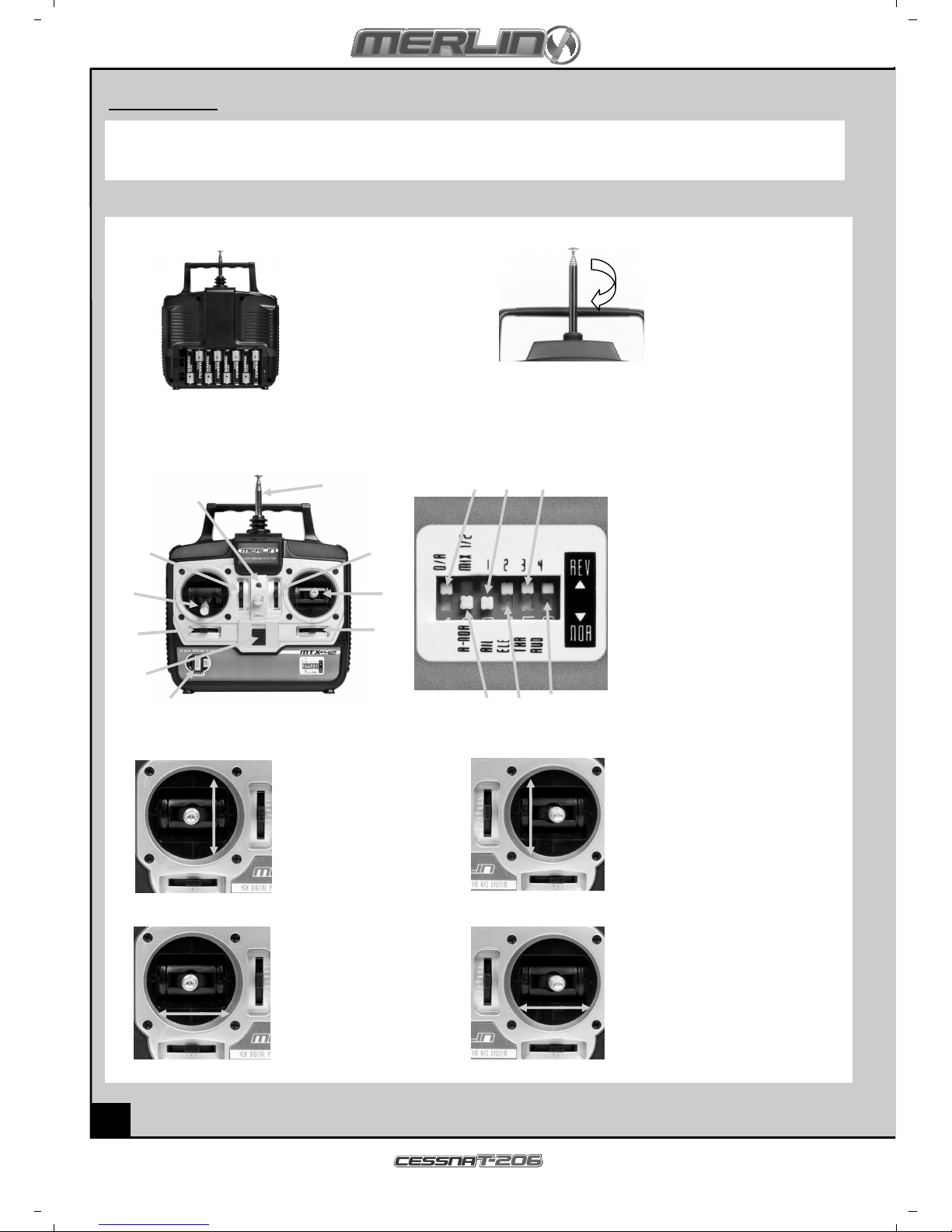
Empfohlenes Werkzeug
Diese Werkzeuge werden it de Produkt itgeliefert, sind aber für Arbeiten an diese Produkt e pfohlen.
Schau stoff-Superkleber Miniatur-Schraubendreher Pack-Klebeband
Batteriepack aufladen
Zu Aufladen der itgelieferten Batterie das itgelieferte Ladegerät verwenden. Wenn andere handelsübliche Produkte verwen-
det werden, zur Ver eidung von Schäden die zugehörigen Anweisungen befolgen.
Die Ladedauer für die Batterie beträgt 130 Minuten.
1. Den 12V Ausgang des 240V Steckdosen-Transfor ator it de Eingang des itgelieferten Ladegeräts verbinden - die
rote Anzeigeleuchte sollte brennen.
2. Die Flugzeug-Batterie in die 7,4V 2-Zellen-Ausgangsbuchse des Ladegeräts einstecken. Nach 5 Sekunden sollte die
Ladeanzeige grün brennen und da it anzeigen, dass die Batterie aufgeladen wird
3. Nach Ende des Aufladevorgangs schaltet das Ladegerät auto atisch ab und die grüne Leuchte erlischt.
4. Die Batterie herausziehen und das Ladegerät vo Trafo trennen.
Wenn nach Einstecken der Batterie die Ladeanzeige nicht grün brennt oder blinkt, ist die Batterie bereits voll aufgeladen.Zu
Aufladen der Batterie a Flugfeld wird in 12V-Anschlußkabel zu Anschließen an eine Autobatterie itgeliefert, das die richtige
Polarität gewährleistet. Rot = Plus-Pol, schwarz = Minus-Pol
Vorsichtshinweise
• Das Ladegerät nur unter Aufsicht eines Erwachsenen verwenden. Das Ladegerät nicht nass oder in der Nähe von Wasser
verwenden.
• Das Ladegerät nicht verwenden, wenn das Kabel ausgefranst oder abgescheuert ist. Bei eine ausgefransten oder ab-
gescheuerten Kabel kann leicht ein Kurzschluß auftreten und Feuer oder Verbrennungen verursachen.
• Wenn Ihre Batterie heiß wird und während des Aufladens 50°C überschreitet, könnte sie defekt sei - wenden Sie sich in
diese Fall bitte an Ihren Händler.
• Wenn während des Aufladens und bei Betrieb das Batteriepack anschwillt oder expandiert, ist es defekt - wenden Sie
sich in diese Fall bitte an Ihren Händler.
• Die Batterie a Ladegerät nie unbeaufsichtigt lassen.

Preparing the transmitter
18
Drosselhebel
9
10 11
12
1
4
7
2
3
5 6
8
13
16
15
14
Höhenruderhebel
1. Hebel nach vorn
drücken erhöht die
Propellergeschwin-
digkeit
2. Hebel zurückziehen
ver indert die Pro-
pellergeschwindigke
it
1
2
1
2
1 2
1. Hebel nach links drücken -
Rolle links, linkes Höhen-
ruder geht nach oben,
rechtes Höhenruder nach
unten
2. Hebel nach rechts drücken -
Rolle rechts, rechtes Höhen-
ruder geht nach oben, linkes
Höhenruder nach unten
1. Hebel nach vorne drücken -
Nase geht nach unten,
Höhenruder schwenkt nach
unten
2. Hebel zurückziehen - Nase
geht nach oben, Höhenruder
schwenkt nach oben
1. Hebel nach links
drücken - Linkskurve,
Seitenruder schwenkt
nach links
2. Hebel nach rechts
drücken - Recht-
skurve, Seitenruder
schwenkt nach rechts
Querruderhebel
1 2
Transmitter
Ihr Merlin Sender ist ein oderner Regler, der auch von eine Anfänger leicht zu bedienen und einzustellen ist. Mit
den unten aufgeführten Schritten stellen Sie sicher, dass der Regler für die Verwendung richtig vorbereitet ist und
Sie die vorhandenen Regel öglichkeiten ganz verstehen.
Batteriefach öffnen, u
die leeren Batteri-
eschächte freizulegen.
Die 8 AA Batterien in die
arkierten Schächte ein-
setzen. Dabei auf die
richtige Richtung der Bat-
terien achten.
Falsch eingesetzte Bat-
terien können zu Schäden
führen.
Die Antenne in das Loch
einsetzen und rechtsheru
(i Uhrzeigersinn) festdre-
hen.
Die Antenne nie über äßig
herausziehen, da it sie
nicht abbricht.
1. Antenne
2. Drosseltri
3. Querrudertri
4. Höhenrudertri
5. Drossel-/Seitenruderhebel
6. Querruder-/Höhenruderhebel
7. Ein-/Ausschalter
8. Batteriestandsanzeige
9. Seitenruder-U kehrschalter
10. Querruder-U kehrschalter
11. Drossel-U kehrschalter
12. Höhenruder-U kehrschalter
13. Schwingquartz
14. Steuerstufenschalter
15. Quer-/Höhenruder-
Mischerschalter
16. Seitenrudertri
eitenruderhebel
Vorbereiten des enders
Table of contents
Languages:
Other Merlin Toy manuals

Merlin
Merlin Condor 1380 User manual

Merlin
Merlin PULSAR150 User manual

Merlin
Merlin POLARIS 400CP User manual

Merlin
Merlin pilot 500 User manual

Merlin
Merlin Tracer 60 Manual

Merlin
Merlin POLARIS 400CP User manual

Merlin
Merlin 6-IN-1 DIY Educational Solar Toy Kit User manual

Merlin
Merlin Tracer 180 User manual

Merlin
Merlin 6-IN-1 DIY Educational Solar Toy Kit User manual