Directechs DB3 User manual

Designed by Installers for Installers
INSTALLATION GUIDE
DB3
2008 Chrysler Aspen. 403.CHRYSLER 7.34
© 2022 Directed, Vista CA
This product is intended for installation by a professional installer only! Attempts to install this
product by a person other than a trained professional may result in severe damage to a vehicle’s
electrical system and components.

Introduction 3
Vehicle function compatibilities 4
Pre-installation and application warnings 5
Installation 6
Wiring diagram with T-Harness CHTHD2 (R1-R7 & R9-R10) or THCHD2 (R1) 6
Wiring diagram 7
Locating components in the vehicle 8
Vehicle connections 9
Module programming 11
Key-type Vehicles 11
Push-to-Start (PTS) Vehicles 12
Connecting the module 13
LED diagnostics and troubleshooting 14
Soft reset 16
Hard reset 16
Feature programming 17
Feature and option list 18
Limited one year consumer warranty 19
Quick reference guide 20
Contents

3403.CHRYSLER 7.34 2008 Chrysler Aspen
©2022 VOXX•DEI LLC. All rights reserved.
Introduction
DB3 is an all-in-one door lock and override module.
Warning!
This module can only be flashed and configured using DirectLink at www.directechs.com or using the Directechs
Mobile application for smartphones. Refer to “Connecting the module” for more information.

4403.CHRYSLER 7.34 2008 Chrysler Aspen
©2022 VOXX•DEI LLC. All rights reserved.
Vehicle function compatibilities
This section lists all the functions compatible with this vehicle for the installation illustrated in this guide.
Parking Lights Control
Arm Factory Security
Disarm Factory Security
Door Lock Control
Door Unlock
Driver Priority Unlock
Trunk / Hatch Release
Control of aftermarket alarm with OEM remote
* Fuel Level
Immobilizer Bypass-Data No Key Req'd
RAP Shut Down (Retained ACC Power)
Remote Start Ready
Remote Start Takeover
SmartStart
Tach / RPM Output
Entry Monitoring ALL Door Pins
Entry Monitoring Hood Pin
Entry Monitoring Trunk/Hatch Pin
Brake Status (foot brake)
E-Brake Status
Ignition Status
5403.CHRYSLER 7.34 2008 Chrysler Aspen
©2022 VOXX•DEI LLC. All rights reserved.
Pre-installation and application warnings
Firmware notes: This section highlights important information for this specific firmware and will assist in
pricing accordingly, as well as bringing awareness to any operational or vehicle limitations.
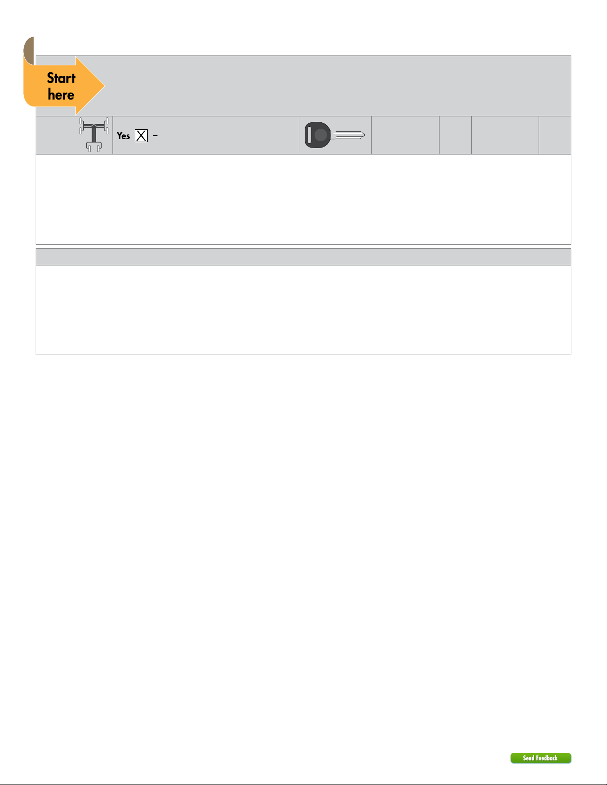
T-Harness
compatible CHTHD2/THCHD2 Keys required for
programming 1Keys required for
operation 0
The optional Plug & Play CHTHD2/THCHD2 T-Harnesses are sold separately. See "Wiring diagram with T-Harness" for more
information on connections and installation instructions.
The OBDII Diagnostic Connector features will remain the same even when the T-Harness is installed.
All T-Harness wires NOT listed in the diagram are NOT required for the installation.
All connectors are displayed from the wire side (unless specified otherwise).
Refer to the "Vehicle connections" following the installation diagram.
General notes: This section highlights important information for this specific firmware.
[1] Tach wire is an optional connection required on some remote starters, which do not support a tach signal in D2D.
[2] When using a THCHD2 (R11) T-Harness and the security light remains ON after performing remote start takeover or the
radio turns ON when performing functions like lock and unlock, CUT and tape the T-04 loop.
[3] When using a CHTHD2 (R1- R6 & R9 - R10) & THCHD2 (R1) T-Harness and the security light remains ON after performing
remote start takeover or the radio turns ON when performing functions like lock and unlock, then CUT the Violet/Green pin
8 and Violet/Brown, pin 9 of the Red 12-pin harness.
6403.CHRYSLER 7.34 2008 Chrysler Aspen
©2022 VOXX•DEI LLC. All rights reserved.
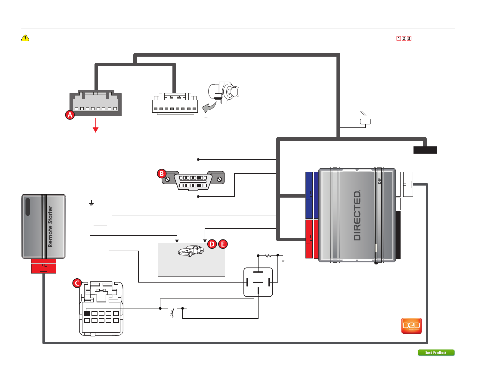
Refer to "Pre-installation and application warnings" for important information, such as the description of each special note referenced in the diagram ( ).
D2D Port
Wiring diagram with T-Harness CHTHD2 (R1-R6 & R9-R10) or THCHD2 (R1 & R11)
HS CAN High: Orange/Green
HS CAN Low: Orange/Brown
16
8
9
1
CAN C Low: Pin 14
CAN C High: Pin 6
(+)12V Input (-) Drivers Door Trigger
(-) RAP Off Output: Yellow/Black
Diagnostic
Connector OBDII
(connector side view)
1412
10 42
(+) Ignition Input/ Output (+) Ignition Input/Output: Pink
(-) Ground
(-) Hood Switch (-) Hood Switch
Refer to the
“Vehicle connections” section
for wire and connector details.
(+) 12V Input
(+) Parking Light Output
(MUX)
Parking Lights:
Pink/Red,
pin 1
4
987
32
106
15
Headlight Switch
(black 10-pin conn.)
CUT
1130 Ω
Resistor
86 85
30
87a
87
Do not
connect
The Remote Start Safety
Override Switch is inactive
(used for RSR only)
XKD2D65
Sentry Key Module
(black 8-pin conn.)
To vehicle
male 8-pin connector
at the ignition switch
To 8-pin Female Connector
at the ignition switch
CHTHD2 (R1-R6 & R9-R10) or THCHD2 (R1-R11)
(optional T-Harness)

7403.CHRYSLER 7.34 2008 Chrysler Aspen
©2022 VOXX•DEI LLC. All rights reserved.
Refer to "Pre-installation and application warnings" for important information, such as the description of each special note referenced in the diagram ( ).
D2D Port
1412
10 42
Wiring diagram
XKD2D65
(+) Parking Light Output
(-) Ground
(-) Hood Switch (-) Hood Switch
HS CAN 1 High: Tan/Black: 3
HS CAN 1 Low: Tan : 4
(AC) Tach Input (AC) Tach Output: Violet/White: 5
(MUX) Ignition Output: Violet/Brown: 9
(MUX) Ignition Output: Violet/Green: 8
(+) Ignition Input/ Output
(+) 12V Input
(MUX)
Parking Lights:
Pink/Red,
pin 1
4
987
32
106
15
Headlight Switch
(black 10-pin conn.)
CUT
1130 Ω
Resistor
86 85
30
87a
87
CAN B High: Pin 6
CAN B Low: Pin 7
(+) Ignition: Pink/White
or Pink/Gray, pin 3
(MUX) Ignition:
Violet/Brown,
pin 1
Sentry Key Module
(black 8-pin conn.,
connector side view)
1 8
Refer to the
“Vehicle connections” section
for wire and connector details.
16
8
9
1
CAN C Low: Pin 14
CAN C High: Pin 6
(-) RAP Off Output: Yellow/Black: 10
HS CAN 2 High: Orange/Green: 5
HS CAN 2 Low: Orange/Brown: 6
Diagnostic
Connector OBDII
(connector side view)


9403.CHRYSLER 7.34 2008 Chrysler Aspen
©2022 VOXX•DEI LLC. All rights reserved.
Vehicle connections
The connection information listed below is specific to the 2008 Chrysler Aspen. Refer to “Pre-installation and application warnings” for a list of important notes.
Data 14-pin blue connector (H1)
Module Connects To
Conn./Pin Color Description Wire Location (+/-) Wire Color
H1/1 Light Green No Connection No Connection
H1/2 Violet/Yellow No Connection No Connection
H1/3 Tan/Black (DATA) HS CAN 1 High Sentry Key Module on ignition switch, black 8 pin plug, pin 6 data white/orange (CAN B BUS)
H1/4 Tan (DATA) HS CAN 1 Low Sentry Key Module on ignition switch, black 8 pin plug, pin 7 data white (CAN B BUS)
H1/5 Orange/Green (DATA) HS CAN 2 High OBD-data link connector, black 16 pin plug, pin 6 data white/pink (Diagnostic CAN C)
H1/6 Orange/Brown (DATA) HS CAN 2 Low OBD-data link connector, black 16 pin plug, pin 14 data pink/red (Diagnostic CAN C)
H1/7 Brown Relay N.O. No Connection No Connection
H1/8 Yellow Relay COM Ignition Output No Connection
H1/9 Orange/Yellow Relay N.C. Ignition Output No Connection
H1/10 Orange/Red Relay N.C. No Connection No Connection
H1/11 Yellow/Red Relay COM No Connection No Connection
H1/12 Brown/Red Relay N.O. No Connection No Connection
H1/13 Red (+) W2W Only - 12 Volt driver kick fuse box, black 40 pin plug, pin 1 + red/gray (40A)
H1/14 Black (-) W2W Only - Ground (chassis ground)
Output 12-pin red connector (H2)
Module Connects To
Conn./Pin Color Description Wire Location (+/-) Wire Color
H2/1 Black/White (-) W2W Only - E-Brake Output Remote Starter
H2/2 Green/Black No Connection No Connection
H2/3 Green/White (-) W2W Only - Door Output Remote Starter
H2/4 Red/Black (-) W2W Only - Trunk Output Remote Starter
H2/5 Violet/White (AC) W2W Only - Tach Output [1] Remote Starter
H2/6 Gray (+) W2W Only - Brake Output Remote Starter
H2/7 Gray/Black No Connection No Connection
H2/8 Violet/Green (MUX) Ignition Output Sentry Key Module on ignition switch, black 8 pin plug, pin 1 MUX violet/brown
H2/9 Violet/Brown (MUX) Ignition Output Sentry Key Module on ignition switch, black 8 pin plug, pin 1 MUX violet/brown
H2/10 Yellow/Black (-) RAP Off Output Driver Door Module, brown 20 pin plug, pin 5 - violet
H2/11 Orange/Black No Connection No Connection
H2/12 Blue/Red (-) W2W Only - Hood Switch Input Remote Starter
Input 10-pin black connector (H3)
Module Connects To
Conn./Pin Color Description Wire Location (+/-) Wire Color

10 403.CHRYSLER 7.34 2008 Chrysler Aspen
©2022 VOXX•DEI LLC. All rights reserved.
Module Connects To
Conn./Pin Color Description Wire Location (+/-) Wire Color
H3/1 Green (-) W2W Only - Lock Input Remote Starter
H3/2 Blue (-) W2W Only - Unlock Input Remote Starter
H3/3 Red/White (-) W2W Only - Trunk Input Remote Starter
H3/4 White/Violet (-) W2W Only - Aux1 Input Remote Starter
H3/5 Violet/Black (-) W2W Only - Aux2 Input Remote Starter
H3/6 White/Black No Connection No Connection
H3/7 Pink/White (+) W2W Only - Pk Light Input
H3/8 Violet (+) W2W Only - Starter Input Remote Starter
H3/9 Pink (+) W2W Only - Ignition Input Remote Starter
H3/10 Blue/White (-) W2W Only - Ground When Running (Status) Input Remote Starter
D2D 4-pin white connector (H4)
Module
Conn./Pin Color Description
H4/1 Blue (Data) TX
H4/2 Black (-) Ground
H4/3 Green (Data) RX
H4/4 Red (+) 12 Volt
RF 2-pin white connector (H5)
Module
Conn./Pin Color Description
H5/1 N/A No Connection
H5/2 N/A No Connection
Additional remote start connections
(Not all of these connections may be required for your installation. Refer to the wiring diagram for vehicle-specific connections.)
Wire Connects To
Wire Location (+/-) Wire Color
12 Volts driver kick fuse box, black 40 pin plug, pin 1 + red/gray (40A)
Ground (chassis ground)
Hood Pin hood pin switch, black 2 pin plug, pin 1 - violet/lt. blue
Ignition Sentry Key Module on ignition switch, black 8 pin plug, pin 3 + pink/gray
Parking Lights MUX - Must use a resistor - Must use a relay Not Applicable
Tachometer any fuel injector ac NOT red
11 403.CHRYSLER 7.34 2008 Chrysler Aspen
©2022 VOXX•DEI LLC. All rights reserved.
Module programming
Refer to “LED diagnostics and troubleshooting” for more information and for troubleshooting purposes.
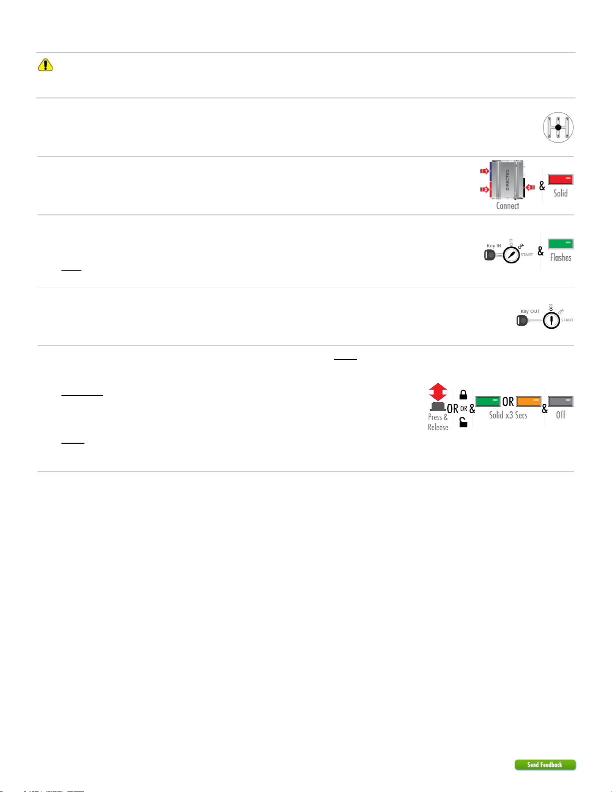
Key-type Vehicles
1Ensure vehicle is in a safe location and cannot move forward during programming. For
vehicles equipped with a manual transmission, make sure the gearshift is in the neutral
position.
2
The harnesses must be connected in this exact order:
a) Connect the 14-pin.
b) Connect the 12-pin.
c) Connect the 10-pin.
When the LED turns on solid red, proceed with the next step.
3
Insert the key into the ignition barrel and turn it to the ON position. It is important to wait for
the LED to start flashing green.
Note: Refer to the "LED Diagnostics" section for troubleshooting if the LED does not flash
green within 15 seconds.
4Turn the key to the OFF position and remove it from the ignition barrel.
5
IMPORTANT: The module will control door locks only if you follow the WITH factory keyless
method.
WITHOUT factory keyless or if OEM remote is unavailable:
Press and release the programming button.
The LED will turn ON solid green OR orange for 3 seconds and then shut off.
WITH factory keyless:
Press Lock or Unlock on the factory transmitter.
The LED will turn ON solid green OR orange for 3 seconds and then shut off.
You have successfully completed the module programming sequence.

12 403.CHRYSLER 7.34 2008 Chrysler Aspen
©2022 VOXX•DEI LLC. All rights reserved.
Push-to-Start (PTS) Vehicles
1Ensure vehicle is in a safe location and cannot move forward during programming. For
vehicles equipped with a manual transmission, make sure the gearshift is in the neutral
position.
2
The harnesses must be connected in this exact order:
a) Connect the 14-pin.
b) Connect the 12-pin.
c) Connect the 10-pin.
When the LED turns on solid red, proceed with the next step.
3
Important! Do not depress the brake pedal.
Press on the PTS button twice (2) to turn the ignition ON. It is important to wait for the LED to
start flashing green.
Note: Refer to the "LED Diagnostics" section for troubleshooting if the LED does not flash
green within 15 seconds.
4Press on the PTS button once (1) more to turn the ignition OFF.
5Press Lock or Unlock on the factory transmitter.
The LED will turns ON solid green OR orange for 3 seconds and then turn off.
You have successfully completed the module programming sequence.

13 403.CHRYSLER 7.34 2008 Chrysler Aspen
©2022 VOXX•DEI LLC. All rights reserved.
Connecting the module
Important!
Make all the required connections to the vehicle, as described in this guide, and double check to ensure everything is correct prior
to moving onto programming.
Warning! To take advantage of advanced features, you must use DirectLink 4.5 (and higher) or the Directechs Mobile application.
Flashing a module using your computer:
1. Connect the interface module to your computer using the XKLoader2.
2. Go to www.directechs.com using Internet Explorer, and select the Flash Module button.
3. Follow the instructions to select your vehicle, installation type, and configure your options.
4. Once you have configured the firmware options, click on the FLASH button.
Flashing a module using your smartphone or tablet:
1. Connect the interface module to your XKLoader3.
2. Launch the Directechs Mobile app on your smartphone or tablet.
3. Select FLASH YOUR MODULE and follow the on screen instructions.
When the flashing operation is successful, you can proceed with the instructions below.
D2D installation
Recommended: Connect the 10-pin, 12-pin and 14-pin harnesses to the module, then
connect the 4-pin D2D harness. 3rd
(14-pin)
1st
(10-pin)
4th
(D2D)
2nd
(12-pin)
OR
W2W installation
If required: Connect the 10-pin and 12-pin harnesses to the module, then connect the 14-pin
harness to the module. 3rd
(14-pin)
1st
(10-pin)
2nd
(12-pin)

14 403.CHRYSLER 7.34 2008 Chrysler Aspen
©2022 VOXX•DEI LLC. All rights reserved.
LED diagnostics and troubleshooting
This section provides LED diagnostics and troubleshooting information to guide you through the various stages of your installation.
Module Programming
LED Description Troubleshooting
Off Module has no power. Make sure the D2D harness is connected and that 12 Volt is present between the red and black wires. If
12 Volt is present, the module may be defective.
Solid red
Waiting to begin the programming
sequence. Ensure the correct programming procedure is being followed.
Flashes green & red Initialization failed. Reset the module and complete the programming again. If the issue persists, please contact Technical
Support.
Solid orange Transponder functions were skipped. (If compatible) when RXT mode is not desired or convenience features are needed, please reset the and
reprogram the module.
Flashes green
All required CAN networks has been
detected. Normal operation.
Flashes orange 1 of 2 CAN networks has been detected. Normal operation.
Flashes orange
slowly
Key2GO initiated. Please follow the steps indicated in “Module programming” to complete the Key2GO programming.
Solid green x 3 secs
Module was successfully programmed with
all functions. Normal operation.
Solid orange x 3 secs
Module was successfully programmed
without transponder functions. Normal operation.
Module Programming - Error codes
LED Description Troubleshooting
Flashes red x 1 CAN2 not detected.
Check the CAN2 Orange/Green and Orange/Brown wire connections. Wake up the data bus by
turning the ignition on and try again. If your installation does not require this connection, skip this step by
pressing the programming button 5 times.
Flashes red x 1 J1850 not detected. Check the J1850 wire connection. Wake up the data bus by turning the ignition on and try again.
Flashes red x 2 CAN1 not detected.
Check the CAN1 Tan and Tan/Black wire connections. Wake up the data bus by turning the ignition on
and try again. If your installation does not require this connection, skip this step by pressing the
programming button 5 times.
Flashes red x 3 Bypass data not detected. Check the bypass line connection. If more than one wire is used, make sure they are not inverted. Ensure
the vehicle still operates correctly using the factory key.
Flashes red x 4 Bypass processing error. The bypass calculation failed. Reset the module and try again. If the condition persists, please contact
Technical Support.
Flashes red x 5 ISO 1 not detected. The Yellow/Black wire did not detect the expected signal. Refer to “Installation (wiring diagrams &
vehicle wiring reference charts)” to check the connections.
Flashes red x 6 ISO 2 not detected. The Orange/Black wire did not detect the expected signal. Refer to “Installation (wiring diagrams &
vehicle wiring reference charts)” to check the connections.
Flashes red x 7 MUX not detected. The Violet/Green or Violet/Brown wire did not detect the expected voltage value. Refer to “Installation
(wiring diagrams & vehicle wiring reference charts)” to check the connections.
External Module Synchronization
LED Description Troubleshooting
(Flashes red, red,
then orange) x 10
OBDII feature not supported. The diagnostic data bus was not detected, therefore the SmartStart features will be limited.

15 403.CHRYSLER 7.34 2008 Chrysler Aspen
©2022 VOXX•DEI LLC. All rights reserved.
Active Ground When Running (Status)
LED Description Troubleshooting
Flashes green
Ground When Running (Status) command
received. The module has initialized the remote start sequence.
Flashes red & orange Ignition ON command received. The module has received the Ignition ON command and is processing the remote start sequence.
Flashes green quickly Start ON command received. The module has received the Start ON command and is processing the remote start sequence.
Flashes red x 10 PTS shutdown error. The PTS output from the module was not activated due to safety protection.
Flashes red x 21 CAN bus incorrectly detected. Verify the CAN1 and CAN2 connections. Refer to “Installation (wiring diagrams & vehicle wiring
reference charts)” to check the connections.
Commands
LED Description Troubleshooting
Flashes orange x 1 LOCK command received. If the bypass module fails to flash, it did not receive the signal. Commands can come from RF or D2D.
Flashes orange x 2 UNLOCK command received. If the bypass module fails to flash, it did not receive the signal. Commands can come from RF or D2D.
Flashes orange x 3 TRUNK command received. If the bypass module fails to flash, it did not receive the signal. Commands can come from RF or D2D.
Flashes orange x 4 AUX1 command received. If the bypass module fails to flash, it did not receive the signal. Commands can come from RF or D2D.
Flashes orange x 5 AUX2 command received. If the bypass module fails to flash, it did not receive the signal. Commands can come from RF or D2D.
Flashes orange x 6 AUX3 command received. If the bypass module fails to flash, it did not receive the signal. Commands can come from RF or D2D.
Shutdown Codes
LED Description Troubleshooting
Flashes green x 1 Takeover successful. Normal operation.
Flashes red x 1 Runsafe was not disabled. No UNLOCK command was received prior to opening the door, or the 45 second timer expired in
takeover mode.
Flashes red x 2 Brake was not detected. The brakes were not detected, which prevents the system from shutting down the vehicle.
Flashes red x 3 Smart key was not detected. The smart key was not detected, which prevents the system from shutting down the vehicle.
Flashes red x 4 Speed was detected. The vehicle was detected as moving, which prevents the system from shutting it down.

16 403.CHRYSLER 7.34 2008 Chrysler Aspen
©2022 VOXX•DEI LLC. All rights reserved.
Soft reset
1
D2D installation
Connect the 10-pin, 12-pin & 14-pin harnesses to the module. Press and hold the
programming button, then connect the 4-pin D2D harness. 3rd
(14-pin)
1st
(10-pin)
5th
(D2D)
2nd
(12-pin)
4th
(Button)
OR
W2W installation
Connect the 10-pin & 12-pin harnesses to the module. Press and hold the
programming button, then connect the 14-pin harness to the module. 4th
(14-pin)
3rd
(Button)
1st
(10-pin)
2nd
(12-pin)
2Wait 3 seconds until the LED turns ON solid orange then release the programming button.
The LED turns ON solid red. &&
Solid SolidRelease
A module reset will only erase the steps perfomed in “Module programming”. The firmware and settings flashed to the module
will not be affected.
Hard reset
Warning Against Executing a Hard Reset!
1
D2D installation
Connect the 10-pin, 12-pin & 14-pin harnesses to the module. Press and hold the
programming button, then connect the 4-pin D2D harness. 3rd
(14-pin)
1st
(10-pin)
5th
(D2D)
2nd
(12-pin)
4th
(Button)
OR
W2W installation
Connect the 10-pin & 12-pin harnesses to the module. Press and hold the
programming button, then connect the 14-pin harness to the module. 4th
(14-pin)
3rd
(Button)
1st
(10-pin)
2nd
(12-pin)
2Wait 3 seconds until the LED turns ON solid orange, and wait 10 more seconds until the
LED starts to flash orange and red. Solid Flashes
&
3Release the programming button. The LED turns ON solid red. &
Release Solid
A hard reset will revert the flashed firmware back to its default factory settings. Depending on the installation, some settings (such
as RFTD and D2D options) may have to be reconfigured. Refer to “Feature and option list”.

17 403.CHRYSLER 7.34 2008 Chrysler Aspen
©2022 VOXX•DEI LLC. All rights reserved.
Feature programming
To enter feature programming routine:
1. Turn the ignition ON, then OFF.
2. Within 5 seconds, press and hold the programming button until the LED turns ON orange (after 3 seconds).
3. Release the Programming button.
4. The LED will flash green once slowly to indicate the feature number is 1. After a short delay, the LED flashes red rapidly to
indicate the current option of feature 1 (e.g. 1 x green followed by 1 x red indicates feature 1 is set to option 1). The flashing
sequence will repeat until a new command is entered.
Changing feature options:
1. Press the lock/arm or unlock/disarm button on aftermarket transmitter to change the option of the selected feature.
2. The LED flashes red rapidly the number of times equal to the current option number. After a short delay, the LED flashes green
slowly the number of times to indicate the current feature. The flashing sequence will repeat until a new command is entered.
Accessing another feature:
1. Press and release the programming button a number of times to advance from the current feature to the next desired feature.
2. The LED flashes green slowly the number of times equal to the feature number. After a short delay, the LED flashes red rapidly
to indicate the current option of the current feature. The flashing sequence will repeat until a new command is entered.
When the maximum number of features or options is reached, the LED will start flashing again from the first feature or option.
Exiting feature programming:
To exit feature programming, press and hold the programming button for 3 seconds or ensure there is no activity on the interface
for 30 seconds. The LED will turn ON orange for 2 seconds to confirm the end of the programming sequence.

18 403.CHRYSLER 7.34 2008 Chrysler Aspen
©2022 VOXX•DEI LLC. All rights reserved.
Feature and option list
It is recommended to configure all the features and options listed below using the configuration tool found on the module flashing page at
www.directechs.com. The web offers more options; however, manual configuration of the features is possible using the information on this
page.
* Default option
Feat
.Operation Flashes / Option Description
1 RFTD Output Type 1. No RF Output* Module is connected to a remote starter using a standard installation.
2. RFTD Output Module is connected to an XL202 using an RSR or RXT installation (when available).
3. SmartStart Module is connected to SmartStart using an RSR or RXT installation (when available).
2 Unlock Driver Priority 1. Driver priority* Unlocks only the driver door when the button is first pressed, and unlocks all doors when it is pressed a second
time within 5 seconds.
2. All Unlocks all doors when the button is first pressed.
3 Trunk 1. Trunk* Will pop the trunk if available.
2. Right Sliding Door When available, will operate the right sliding door.
3. Left Sliding Door When available, will operate the left sliding door.
4 Aux1 1. Trunk Will pop the trunk if available.
2. Right Sliding
Door* When available, will operate the right sliding door.
3. Left Sliding Door When available, will operate the left sliding door.
5 Aux2 1. Trunk Will pop the trunk if available.
2. Right Sliding Door When available, will operate the right sliding door.
3. Left Sliding
Door* When available, will operate the left sliding door.
6 Heated Seats 1. Disabled* No operation.
2. Enabled When the feature is enabled, it will activate the Heated Seats and heated steering wheel.
7 Heated
Seats/Defroster
Temperature Control
1. 32 °F (0 °C)* When Heated Seats or Defroster feature is enabled, it will activate the feature upon remote start when
temperature is below 32 °F (0 °C).
2. 23 °F (-5 °C) When Heated Seats or Defroster feature is enabled, it will activate the feature upon remote start when
temperature is below 23 °F (-5 °C).
3. 41 °F (5 °C) When Heated Seats or Defroster feature is enabled, it will activate the feature upon remote start when
temperature is below 41 °F (5 °C).
4. Always ON When Heated Seats or Defroster feature is enabled, it will activate the feature at any temperature.
8 Heated Seats
Temperature Level
1. High* When Heated Seats are activated, they will be set to HIGH.
2. Low When Heated Seats are activated, they will be set to LOW.
9 Smart OEM Alarm
Control
1. Disabled The OEM alarm will not be controlled by the interface upon remote start. No disarm or arm command will be
executed at the beginning or end of the sequence; it must be controlled by the Remote Starter.
2. Safelock Smart OEM Alarm Control will behave like a standard Safelock feature on a remote starter. It will unlock at the
beginning of the sequence, and relock after start and shutdown.
3. Enabled*
Smart OEM Alarm Control will synchronize with the OEM alarm so that it will disarm and rearm the vehicle in the
remote start sequence, only when required. Smart OEM Alarm Control will monitor the alarm and door lock
status to detect if the disarm or rearm is required. If the vehicle is unlocked or is not equipped with factory alarm,
the disarm/rearm will not be executed.

19 403.CHRYSLER 7.34 2008 Chrysler Aspen
©2022 VOXX•DEI LLC. All rights reserved.
Limited 12 Months Consumer Warranty
VOXX DEI LLC (the Company) warrants to the original purchaser of this product that should this product or any part
thereof, under normal use and conditions, be proven defective in material or workmanship within 12 months from the date
of original purchase, such defect(s) will be repaired or replaced with new or reconditioned product, (at the Company’s
option) without charge for parts or repair labor. A transmitter for a vehicle security or remote start system is warranted for
12 months from he date of original purchase.
To obtain repair or replacement within the terms of this Warranty, the product is to be delivered with proof of warranty
coverage (e.g. dated bill of sale), authorization number, specication of defect(s), transportation prepaid, to an approved
warranty station. This warranty is not transferable.
This Warranty does not cover damage to the vehicle’s electrical system or costs incurred for the installation, removal or
reinstallation of the product. This Warranty does not cover batteries, broken LCD transmitter display screens, nor apply
to any product or part thereof which, in the opinion of the Company, has suered or been damaged through alteration,
improper installation, mishandling, misuse, abuse, neglect, accident, or by removal or defacement of the factory serial
number/bar code label(s).
This Warranty is in lieu of all other express warranties or liabilities. ANY IMPLIED WARRANTIES, INCLUDING ANY
IMPLIED WARRANTY OF MERCHANTABILITY, SHALL BE LIMITED TO THE DURATION OF THIS WRITTEN
WARRANTY. ANY ACTION FOR BREACH OF ANY WARRANTY HEREUNDER INCLUDING ANY IMPLIED WARRANTY
OF MERCHANTABILITY MUST BE BROUGHT WITHIN A PERIOD OF 24 MONTHS FROM DATE OF ORIGINAL
PURCHASE. IN NO CASE SHALL THE COMPANY BE LIABLE FOR ANY CONSEQUENTIAL
OR INCIDENTAL DAMAGES FOR BREACH OF THIS OR ANY OTHER WARRANTY. No person or representative is
authorized to assume for the Company any liability other than expressed herein in connection with the sale of this product.
The company does not warrant that this product cannot be compromised or circumvented. THE EXTENT OF THE
COMPANY’S LIABILITY UNDER THIS WARRANTY IS LIMITED TO THE REPAIR OR REPLACEMENT PROVIDED
ABOVE AND, IN NO EVENT, SHALL THE COMPANY’S LIABILITY EXCEED THE PURCHASE PRICE PAID BY
PURCHASER FOR THE PRODUCT WITHOUT INSTALLATION LABOR.
Some states do not allow limitations on how long an implied warranty lasts or the exclusion or limitation of incidental or
consequential damage so the above limitations or exclusions may not apply to you. This Warranty gives you specic legal
rights and you may also have other rights which vary from state to state.
VOXX DEI LLC, 2351 J. Lawson Blvd., Orlando, Florida 32824

20 403.CHRYSLER 7.34 2008 Chrysler Aspen
©2022 VOXX•DEI LLC. All rights reserved.
Quick Reference Guide
Vehicle takeover with Push-to-Start (PTS)
1Close the vehicle doors, hood and trunk, then send
the Remote Start command to start the vehicle.*
14:36
Press Remote
Start button*
2Send the Unlock command on the factory or
aftermarket remote.*
14:36
Press Unlock on
either remote*
Complete the following steps within 45 seconds or the vehicle will shut down.
3Enter the vehicle, while making sure the factory
remote is inside with you.
14:36
Enter vehicle
with remote
4Press the PTS button twice.
5Depress the brake pedal, put the car in gear and
drive off.
Ready to
drive off
* Icon and remote appearance may differ depending on the model purchased.
Pit stop/idle mode
1Stop the vehicle in a safe parking spot and put the
gear in Park (P).
Put
gear in
Park
2
Press the Remote Start button on the transmitter.*
The parking lights will flash once to indicate the
vehicle is now in Pit Stop Mode. Parking lights flash x1
14:36
Press Remote
Start button*
&
3Press the PTS button once or remove the key from
the ignition. OR
4
It is safe to leave the engine running and exit the
vehicle with the factory remote in hand.
Note: We recommend that you always lock the
doors of your vehicle when leaving it unattended.
14:36
Exit vehicle
with remote
* Icon and remote appearance may differ depending on the model purchased.
Sending commands to your vehicle
Whether you want to remote start the engine, lock/unlock the doors or pop the trunk,
there are 3 possible ways you can send commands to your vehicle, using the:
• Factory remote.
• Aftermarket remote.
• Directed SmartStart application via your smartphone.
If applicable, you can also start the engine remotely by pressing the Lock button 3
times quickly on your factory remote.
Vehicle takeover with regular key
1Close the vehicle doors, hood and trunk, then send
the Remote Start command to start the vehicle.*
14:36
Press Remote
Start button*
2Send the Unlock command on the factory or
aftermarket remote.*
14:36
Press Unlock on
either remote*
3Enter the vehicle, while making sure the factory
remote is inside with you.
14:36
Enter vehicle
with remote
4Insert your key in the ignition barrel and turn it to the
ON position.
START
Key OUT
ON
OFF
START
Key IN
ON
OFF
START
Key IN
ON
OFF
START
Key IN
ON
OFF
5Depress the brake pedal, put the car in gear and
drive off.
Ready to
drive off
* Icon and remote appearance may differ depending on the model purchased.
Other manuals for DB3
18
This manual suits for next models
1
Table of contents
Other Directechs Automobile Electronic manuals

Popular Automobile Electronic manuals by other brands


Conrad Electronic
Conrad Electronic 85 59 17 operating instructions

Boyo
Boyo VTM7012FHD user manual

Volkswagen
Volkswagen 3C0 054 630 Assembly instructions

KLAUS Multiparking
KLAUS Multiparking trendvario6X00 Service manual

Vision
Vision VAE 225 Installation & user manual

Audiovox
Audiovox Auto Security AA-9103N installation guide


