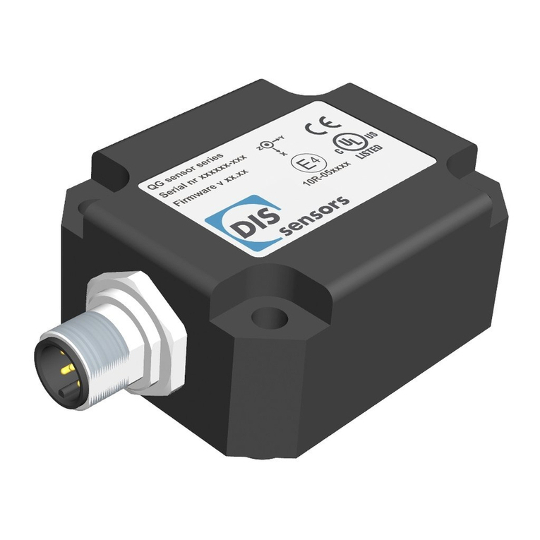
DIS Sensors QG65N2 Series User manual

rin
USER MANUAL
QG65N2 SAE J1939 Inclinometer (Type JB)
V1.1, Mar-22

Page 1of 32
User Manual - QG65N2 SAE J1939 Inclinometer (Type JB) V1.1
Contents
Contents ..................................................................................................................................................................................... 1
1. Safety information ............................................................................................................................................................ 2
1.1. Intended use ........................................................................................................................................................... 2
1.2. Incorrect use ........................................................................................................................................................... 2
1.3. Sensor defective...................................................................................................................................................... 2
2. About this manual............................................................................................................................................................. 3
2.1. Intended use ........................................................................................................................................................... 3
2.2. Symbols used in the text ......................................................................................................................................... 3
2.3. Copyright................................................................................................................................................................. 3
2.4. Document revision control...................................................................................................................................... 4
3. Quick reference................................................................................................................................................................. 5
4. Installation guide .............................................................................................................................................................. 6
4.1. Mechanical drawing ................................................................................................................................................ 6
4.2. Mounting................................................................................................................................................................. 6
4.3. Connection .............................................................................................................................................................. 7
4.4. CAN termination...................................................................................................................................................... 8
5. Technical data ................................................................................................................................................................... 8
6. Functional description ...................................................................................................................................................... 9
6.1. Inclination measurement principle ......................................................................................................................... 9
6.2. Measuring axis and direction .................................................................................................................................. 9
6.2.1. Measuring axis and direction for Inclination ................................................................................................. 9
6.2.2. Measuring axis and direction for acceleration ............................................................................................ 10
6.3. Signal processing ................................................................................................................................................... 11
6.3.1. Sampling rate............................................................................................................................................... 11
6.3.2. Filter algorithm ............................................................................................................................................ 11
6.3.3. Digital filters ................................................................................................................................................ 11
6.4. Boot-up procedure ................................................................................................................................................ 12
6.5. Output format ....................................................................................................................................................... 13
6.5.1. Inclination outputs PGN 65280 (FF00h)....................................................................................................... 13
6.5.2. Acceleration outputs PGN 65283 (FF03h). .................................................................................................. 14
6.6. Sensor configuration (PGN 61184) ........................................................................................................................ 14
6.7. Load factory default settings................................................................................................................................. 16
6.8. Zero adjustment .................................................................................................................................................... 17
6.9. Firmware management......................................................................................................................................... 19
7. SAE J1939 specification................................................................................................................................................... 20
7.1. PDU (Protocol Data Unit) ...................................................................................................................................... 20
7.2. CAN-ID (CAN Identifier) ......................................................................................................................................... 20
7.3. PGN (Parameter Group Number) .......................................................................................................................... 21
7.4. SPN (Suspect Parameter Number) ........................................................................................................................ 23
7.5. NAME and ACM (PGN 60928) ............................................................................................................................... 23
8. Parameter overview........................................................................................................................................................ 25
9. Configuration examples .................................................................................................................................................. 27
9.1. Change device address.......................................................................................................................................... 27
9.2. Change baud rate .................................................................................................................................................. 27
9.3. Enable/Disable/Set cycle time PGNs ..................................................................................................................... 28
9.4. Save changes to the sensor ................................................................................................................................... 29
9.5. Restore factory default ......................................................................................................................................... 29
9.6. Read vendor ID...................................................................................................................................................... 30
9.7. Zero adjustment .................................................................................................................................................... 31
10. Abbreviations and definitions ......................................................................................................................................... 32
11. Normative references ..................................................................................................................................................... 32

Page 2of 32
User Manual - QG65N2 SAE J1939 Inclinometer (Type JB) V1.1
1. Safety information
1.1. Intended use
The QG65N2 J1939 Inclinometer is a MEMS-based inclination sensor with J1939 interface. This device provides
precise and reliable inclination measurement in (semi)static conditions. The use of this device in a machine or
system is permitted only under the following conditions:
•The user is trained and competent in the integration and use of inclination sensors in machinery.
•The user is familiar with the contents of both the datasheet and user manual.
•The user has a full understanding of CAN and J1939.
•The device is used within the specified environmental conditions.
•The device is properly configured for its intended use.
•The device is mounted correctly as described in the datasheet and user manual.
•The device data is expressly not interpreted as safety data, except when used redundantly in a control system that is
designed and tested for cross-check functionality between the primary and redundant devices.
1.2. Incorrect use
•Use of non-standard CAN cables.
•Device mounted incorrectly.
•Zero adjustment outside the specified range.
•Incorrect or absent CAN bus termination.
•Device used outside the specifications.
1.3. Sensor defective
The sensor is considered “defective” when
•No CAN output can be detected.
In the event of uncertainty, contact the distributor or manufacturer. Any unauthorised modification or unapproved
use will void both the warranty and any liability on the part of the manufacturer.

Page 3of 32
User Manual - QG65N2 SAE J1939 Inclinometer (Type JB) V1.1
2. About this manual
2.1. Intended use
This manual applies solely to the QG65N2 J1939 inclinometer (Type JB) with the following model designations:
•QG65N2-KIXv-360-CANJ-C(F)M-UL —— 1 axis, ± 180°, vertical mounting, std. acccuracy.
•QG65N2-KDXYh-090-CANJ-C(F)M-UL —— 2 axes, ± 90°, horizontal mounting, std. acccuracy.
•QG65N2-KDXYh-030-CANJ-C(F)M-UL —— 2 axes, ± 30°, horizontal mounting, std. acccuracy.
•QG65N2-KIXv-360H-CANJ-C(F)M-UL —— 1 axis, ± 180°, vertical mounting, high acccuracy.
•QG65N2-KDXYh-090H-CANJ-C(F)M-UL —— 2 axes, ± 90°, horizontal mounting, high acccuracy.
•QG65N2-KDXYh-030H-CANJ-C(F)M-UL —— 2 axes, ± 30°, horizontal mounting, high acccuracy.
DIS product code can be identified here.
2.2. Symbols used in the text
h Subscript for hexadecimal values.
d Subscript for decimal values.
Caution that indicates either potential damage to the sensor or explains how to
avoid a problem.
Important information.
→Cross-reference
2.3. Copyright
© Copyright 2022 DIS Sensors bv.
This manual is subject to change without notice.
All rights according to the copyright remain explicitly reserved for DIS Sensors bv.

Page 4of 32
User Manual - QG65N2 SAE J1939 Inclinometer (Type JB) V1.1
2.4. Document revision control
Version
Date(y-m-d)
Revision
V1.0
2022-01-10
1st release.
V1.1
2022-03-08
Certain indices are not supported in the J1939 interface.
Removed from parameter list. Correct description of signal
processing. Function mode etc not supported.
Table 1 - Document revision

Page 5of 32
User Manual - QG65N2 SAE J1939 Inclinometer (Type JB) V1.1
3. Quick reference
General
•1-axis ± 180° and 2-axes ± 30°/± 90° inclinometer
•Output type: SAE J1939
•Internal sample rate MEMS: 1000Hz; output rate: 100 Hz
•2nd order Low pass Bessel filter: 10Hz (→index 3014h)
•Output filter: adjustable 1st order LPF (→ index 300Eh)
•Approved for automotive use, approval number: E4-10R-05-4662
CAN, J1939
•CAN interface: CAN2.0 A/B (compliant with ISO11898-1&2)
•Application layer: SAE J1939 (29-bit CAN identifier)
•CAN bus bit rate: 250 kbit/s default, optional 500kbit/s
•Device address: 128d (80h) default
•PGN cycle time: 100ms default
•Output data: PGN 65280 (Inclination), PGN 65283 (Acceleration)
•Sensor configuration: PGN 61184 (EF00h)
•Zero adjustment via index 300Fh
•Negative values: two’s complement
•Byte-sequence on CAN bus: little-endian (least significant byte first)

Page 6of 32
User Manual - QG65N2 SAE J1939 Inclinometer (Type JB) V1.1
4. Installation guide
4.1. Mechanical drawing
Figure 1 - Mechanical drawing of QG65N2 with a male M12.
4.2. Mounting
•Use the 4 screws provided (M5x25 mm zinc plated steel Pozidrive pan head screws with self-tapping PZ
DIN7500CZ) to mount the device.
•If a software zero adjustment is impossible or undesirable, DIS provides an optional reference solution of
replacing 2 of the provided screws with 2 optional 4mm Ø positioning pins, which can serve as
mechanical reference.
•Tightening torque max. 2.5 Nm. A higher torque can cause damage to the housing or the internal
electronics.
•Fix the sensor to a perfectly flat surface.
•A 1-axis inclinometer must be mounted vertically. The factory default zero position is with the male
connector pointing down as shown in Figure 2 . Sensor can be zero adjusted at any position within the full
range.
•A 2-axis inclinometer must be mounted horizontally. The factory default zero position is shown in Figure
2. After installation, sensor can be zero adjusted to eliminate the mechanical offsets within a ±5° offset
range.
Figure 3 - Vertical mounting 1-axis inclination
Figure 2 - Horizontal mounting 2-axes inclination

Page 7of 32
User Manual - QG65N2 SAE J1939 Inclinometer (Type JB) V1.1
4.3. Connection
The sensor is equipped with either a single 5-pole M12 (A-coded) male connector according to IEC 61076-2-101, or
with an additional 5-pole M12 (A-coded) female connector. This is specified in the suffix of the device model
designation: suffix CM indicates single male connector; suffix CFM indicates both a female and a male connector.
The advantage of two connectors is that devices can be daisy-chained in the CAN network. The voltage supply is
forwarded from the male to the female connector, providing both power and bus-connection to the next sensor
with a single cable harness. The connection between male and female connector acts as an internal T-junction.
The pin assignment is according to CiA 303-1 V1.8.0.
Pin
Assignment
Pin 1
Shield
Pin 2
Vcc
Pin 3
Gnd & CAN_GND
Pin 4
CAN_H
Pin 5
CAN_L
Figure 4 - Pin definition
•The maximum current for the internal T-junction is 2.5 A. This must be taken into account when using daisy-chained
connections.
•The voltage supply must be dimensioned to prevent exceeding the specified voltage limits.
•The power consumption is about 50mA typical.
•This device must be connected to a class 2 power supply.
•Connect the sensor only to an approved CAN controller which must have a grounded shield. Alternative: connect the
sensor housing to a grounded shield. All mentioned EMC standards that are met (see Declaration of Conformity)
have been done with the housing connected to a grounded shield.
Installation of wiring and the opening and closing of electrical connections must only be carried out in de-energized
state!Short-circuits, voltage spikes, etc. can cause malfunctions and/or cause the installation to become uncontrolled,
creating a serious risk of injury or damage to property.

Page 8of 32
User Manual - QG65N2 SAE J1939 Inclinometer (Type JB) V1.1
4.4. CAN termination
A CAN bus should be terminated properly to prevent signal reflections. The QG65N2 J1939 Inclinometer has an
internal 120 Ohm termination resistor. By default, this is disabled.
A separate M12 termination resistor and T-connector are also available as accessories.
Figure 5 - M12 CAN terminator male 5p.
Order code: 10217
Figure 6 - M12 CAN terminator female 5p.
Order code: 10194
Figure 7 - M12 T-connector 5p.
Order code: 11822
The advantage of using a separate termination plug instead of the internal termination resistor is that an external
termination plug is clearly visible. This helps to prevent an inadvertent double termination that could cause the
entire CAN bus to malfunction.
5. Technical data
Please refer to the datasheet of your product.

Page 9of 32
User Manual - QG65N2 SAE J1939 Inclinometer (Type JB) V1.1
6. Functional description
6.1. Inclination measurement principle
QG65N2 Inclinometers measure inclination by measuring static acceleration of gravity using an accelerometer
MEMS. In static conditions, inclination measurement by this principle is accurate and reliable.
However, the vibrations or movements present on almost all industrial machines generate undesirable g-forces.
These dynamic g-forces accumulate and overlay the static g-forces, causing a ‘dirty’ inclination output that includes
spurious or noise components.
A low-pass filter can stabilize the output, that can be enough for some applications. The downside of this filtering is
that it increases the reaction time (latency) of the inclinometer. In a control system this results in a limit on the
speed of movements, and reduced machine efficiency.
If the dynamic effects are dominant and acceptable delay time is limited, please consider our Dynamic
inclinometer, where with the help of a gyroscope a sort of filtering is achieved without having the downside of
delay time.
6.2. Measuring axis and direction
6.2.1. Measuring axis and direction for Inclination
A single-axis inclinometer (vertical mount) measures the inclination in the vertical plane over the full range 0-
360° (X-output). The default 0° position and the measuring direction are shown in Figure 8.
Figure 8 - Measuring axis and direction of 1-axis inclination.

Page 10 of 32
User Manual - QG65N2 SAE J1939 Inclinometer (Type JB) V1.1
A dual-axis inclinometer (horizontal mount) measures the inclination on both X and Y axis. Measuring range is
up to 90°. Due to the measurement principle, only one axis may tilt more than 45°.
Figure 9 – Measuring axis and direction of 2-axis inclination.
Cross-tilt error: when the cross axis (axis perpendicular to the measuring axis) tilts more than 45° during the measurement,
the measuring axis will be disabled. The sensor will send a fixed CAN output to indicate that the sensor is now at a cross-tilt error
position (→Knowledgebase): 20000d(200°) for the measuring range ±180°, ±30°/ ±90°, and 40000d(400°) for the measuring
range 0°-360°.
6.2.2. Measuring axis and direction for acceleration
The device measures the acceleration values on all 3 axes. The measuring direction of three axes in the factory
default setting is shown in Figure 10. Raw acceleration value range are up to ±1.5/±2.0 g with resolution of 0.001g.
Figure 10 – Measuring axis and direction of acceleration.

Page 11 of 32
User Manual - QG65N2 SAE J1939 Inclinometer (Type JB) V1.1
6.3. Signal processing
Figure 11 - Signal processing
6.3.1. Sampling rate
Each axis of the acceleration MEMS is sampled by the internal microcontroller at a rate of 1000 Hz. Those samples
are fed into the filter algorithm and will be processed further.
6.3.2. Filter algorithm
Filter algorithm is implemented to improve the quality of the sampled raw data. The calculation rate is 100Hz.
6.3.3. Digital filters
To eliminate noise or reduce the bandwidth, the inclination values can be further processed with extra digital
filters. The values are predefined by DIS.
MEMS Sampling
•3 DOF raw outputs
•Sampling rate 1000Hz
Filter Algorithm
•Calculation rate 100Hz
Digital Filters
•2nd order Bessel LPF
(10Hz)
•Output filter

Page 12 of 32
User Manual - QG65N2 SAE J1939 Inclinometer (Type JB) V1.1
6.4. Boot-up procedure
When the device is powered on, the device will be initialised with the last-stored parameters. When initialisation is
complete, an Address Claim Message (ACM) containing the address used and NAME will be sent. (→7.5 NAME and
ACM (PGN 60928))
Figure 12 – example ACM at boot-up
The CAN-ID 18EEFF80 shows that the sensor has a default source address of 80h.
The data of the ACM is
Figure 13 - ACM data
This is the 64-bit device NAME for DIS sensors which contains the following fields:
MSB
64 bits
LSB
1 bit
3 bit
4 bit
7 bit
1 bit
8 bit
5 bit
3 bit
11 bit
21 bit
Arbitrary
Address
Capable
Industry
group
Vehicle
system
Instance
Vehicle
System
Reserved
Function
Function
Instance
ECU
Instance
Manufacturer
Code
Identify Number
1
000
0000
0000000
0
10010011
00000
000
10001001101
000110000110100111111
Table 2 – NAME definition and data example
Bit length
Definition
Data
Meaning
21 bits
Identify Number
000110000110100111111
b
The least 21 bits of the 32-bit serial
number of the sensor
11 bits
Manufacturer Code
10001001101
b
= 1101
d
DIS Sensors B.V.
3 bits
ECU Instance
000
b
5 bits
Function Instance
00000
b
8 bits
Function
10010011
b
= 147
d
Inertial Sensor
1 bit
Reserved
0
b
7 bits
Vehicle System
0000000
b
4 bits
Vehicle system
Instance
0000
b
3 bits
Industry group
000
b
Global, applies to all industries
1 bit
Arbitrary Address
1
b
yes
Table 3 - NAME explanation

Page 13 of 32
User Manual - QG65N2 SAE J1939 Inclinometer (Type JB) V1.1
6.5. Output format
The device supports 2 different parameter groups (Tx PGNs):
•Proprietary B Tx PGN1 65280 for Longitudinal, Lateral Inclination (Availability of lateral information depends on sensor
type)
•Proprietary B Tx PGN2 65283 for X, Y, Z Acceleration
6.5.1. Inclination outputs PGN 65280 (FF00h).
PGN
Name
Priority
SPN
position(bit)
SPN
Width(bit)
Resolution
Offset
Data Range
65280
d
FF00h
X axis
(Longitudinal)
3
0
16
0.01°/bit
−
-90° - +90°
Y axis
(Lateral)
3
16
16
0.01°/bit
−
-90° - +90°
Table 4 – Transmit PGN1 inclination 2-axis
PGN Name Priority SPN
position(bit)
SPN
Width(bit)
Resolution Offset Data Range
65280d
FF00h
X axis
(Longitudinal)
3 0 16 0.01°/bit −-180° - +180°
Table 5 - Transmit PGN1 inclination 1-axis
The angle can be calculated with formula: α= J1939 output / 100. (α = angle in degrees, factory resolution is 0.01°)
Figure 14 - Output 1-axis ±180° sensor
Figure 15 - Output 2-axis ±90° sensor
Figure 16 - Output 2-axis ±30° sensor
Example – Inclination output of a 1-axis sensor.
The first 2 bytes are the angle value, the rest 6 bytes are not used.
Byte0
Byte1
0A
h
0A
h
Inclination output: 0A0A
h
= 2570
d
= 25.70°
Table 6 - Output 1-axis ±180° sensor explanation

Page 14 of 32
User Manual - QG65N2 SAE J1939 Inclinometer (Type JB) V1.1
Example – Inclination output of a 2-axis sensor
The first 2 bytes are X inclination, and the second 2 bytes are Y inclination. The rest 4 bytes are not used.
Byte0
Byte1
Byte2
Byte3
X inclination
Y inclination
8E
h
FC
h
4B
h
08
h
FC8E
h
= -882
d
= -8.82°
084B
h
= 2123
d
= 21.23°
Table 7 – Output 2-axis 90° sensor explanation
6.5.2. Acceleration outputs PGN 65283 (FF03h).
PGN
Name
Priority
SPN
position(bit)
SPN
Width(bit)
Resolution
Offset
Data Range
65283
d
FF03h
X axis
(Longitudinal)
3
0
16
0.001g/bit
−
H series: -1.5g to +1.5g
Std. series: -2.0g to +2.0g
Y axis
(Lateral)
16
16
0.001g/bit
−
H series: -1.5g to +1.5g
Std. series: -2.0g to +2.0g
Z axis
(Vertical)
32
16
0.001g/bit
−
H series: -1.5g to +1.5g
Std. series: -2.0g to +2.0g
Table 8 - Transmit PGN2 acceleration
Acceleration can be calculated with formula: a = J1939 output / 1000. (a = acceleration in g, factory resolution is
0.001g)
Figure 17 - Output acceleration high accuracy series
Figure 18 - Output acceleration std. accuracy series
For example:
Figure 19 - Acceleration output trace
The 6 bytes data are defined as below.
Byte0
Byte1
Byte2
Byte3
Byte4
Byte5
X acceleration
Y acceleration
Z acceleration
EA
h
FF
h
0A
h
00
h
18
h
FC
h
FFEA
h
= -22
d
= -0.022g
000A
h
= 10
d
= 0.010g
FC18
h
= -1000
d
= -1.000g
6.6. Sensor configuration (PGN 61184)

Page 15 of 32
User Manual - QG65N2 SAE J1939 Inclinometer (Type JB) V1.1
For reading and writing the sensor configuration, Prop A PGN 61184 (EF00h) (->PGN (Parameter Group Number)) is
used.
Example – Read serial number.
Figure 20 - CMD read serial number
The 8 bytes data are defined as below:
D0
D1
D2
D3
D4
D5
D6
D7
Parameter Index CMD Sub index
/Status
Data0 Data1 Data2 Data3
Parameter index Index of the PGN parameter. (→ 8 Parameter overview)
CMD 01h = Command for read data
02h = Command for write data
Sub Index: message to the sensor: Sub index of the PGN parameter. (→8 Parameter
overview)
message from the sensor: Status reply
Message
Description
00
h
Ok processing successfully
F0
h
Invalid index
F1
h
Invalid parameter, parameter out of range
F2
h
EEPROM error
Data0 to Data3 0 to 4 data bytes (Number of valid bytes depends on the parameter)
Table 9 - PGN 61184 data definition
More configuration examples can be found in 9 Configuration examples.

Page 16 of 32
User Manual - QG65N2 SAE J1939 Inclinometer (Type JB) V1.1
6.7. Load factory default settings
Factory reset or load factory default settings allows users to restore the device to its original manufacturer settings.
The customer settings which were saved to the EEPROM will be overwritten by the factory default settings.
With index 1011h, the factory default settings below can be restored. Customised products may have different
factory default values, which may deviate from this manual. See the datasheet of your customized products for
these customized factory default values.
DIS factory default
Parameters Index DIS standard default value
Device Address
3101h80h
Baud Rate
3001h03h - 250 kBit/s
PGN1 (65280)
3102hCycle time = 100d = Enabled
PGN2 (65283)
3103hCycle time = 0d = Disabled
Table 10 – DIS standard factory default communication parameters
Procedures:
Example:
Figure 21 - Restore default settings
A new power cycle is required to enable the factory default settings after a “load”. Do not execute “save” before you restart
the device, as this will cause the current working environment settings to overwrite (i.e. store) the default factory settings.
Restore default
parameters New Power Cycle Default
value valid
•Write “load” to sub-index 01h = All parameters will be restored.
•Write “load” in ASCII or “64616F6Ch” have the same effect.

Page 17 of 32
User Manual - QG65N2 SAE J1939 Inclinometer (Type JB) V1.1
6.8. Zero adjustment
Zero adjustment allows users to compensate for mechanical offsets of a horizontally mounted 2-axis device or set a
customised 0° position of a vertically mounted 1-axis sensor. The measured inclination value at the 0° position will
be stored in the device as a permanent offset, which is used to calculate the actual inclination output of the device.
The zero offset value can be read from Index 6013h, 6023h.
Zero adjustment can be done in two ways and can be repeated at any time.
1. Via Index 300FhZero adjustment.
To perform a zero adjustment, write the corresponding value to index 300Fhsubindex 00h. The zero adjustment can be
done for each axis separately or for all axes at the same time. Status information of the result is available from index
300Fh.
Value
Response
01
h
Start zero adjustment X-axis - inclination
00
h
= Successful; FF
h
= Failed
02
h
Start zero adjustment Y axis - inclination
00
h
= Successful; FE
h
= Failed
03
h
Start zero adjustment X and Y axis - inclination
00
h
= Successful; FD
h
= Failed
Table 11 - Definition index 300Fh
For example:
Write 03h to zero both X and Y axis.
Figure 22 - commands to zero both X and Y axis
The sensor returns 00hin the data byte4 indicating that the zero adjustment is successful.
Figure 23 - response from the sensor indicating that zero is successful (data=00)
And the live output shows the sensor is indeed zeroed.
Figure 24 - sensor live output
If the sensor is zeroed at an illegal position, the response (byte4) will be FF/FE/FDh
Figure 25 - response shows that zero at X and Y axis both failed.
The offset value will be stored permanently in the device without “save” to index 1010h.

Page 18 of 32
User Manual - QG65N2 SAE J1939 Inclinometer (Type JB) V1.1
2. Via Index 6012h, 6022h Pre-set inclination value.
To set the output of X/Y axis to 0°, write 0000h to index 6012h / 6022hat your desired 0° position. The offset will be
stored in Index 6012h, 6022h. Those parameters must be saved to the device.
Index Sub-index Definition Value Example
6012h00h Pre-set inclination X-axis 0000d - 0°
6022h00h Pre-set inclination Y axis 0100d - 1°
Table 12 - Index 6012/6022h definition
Example - Pre-set the X axis to 0°
Figure 26 - commands to pre-set X axis to 0°
Figure 27 - response from the sensor indicating pre-set is successful (Byte3=00h)
Figure 28 - sensor live output shows that The X axis is zeroed
When an out-of-range pre-set value is sent, the sensor sends “F1” as response indicating “Invalid
parameter, parameter out of range” (->6.6 Sensor configuration)
Figure 29 - pre-set X angle to 1194h/45°
Figure 30 - response from sensor indicating that pre-set is failed. (Byte3=F1h)
1-axis ±180° sensors can be zero adjusted over the full range, the position of the male connector is at customer
discretion.
2-axis ±30°/±90° sensors can only be zero adjusted in a horizontal position within an offset limit of ±5°.
After you load factory default settings, the sensor will be restored with the factory zero offset, which means the pre-set
inclination value will be restored to 00h, index 6013hand 6023h will be rewritten to a factory default value and you need
to zero your sensor again.

Page 19 of 32
User Manual - QG65N2 SAE J1939 Inclinometer (Type JB) V1.1
6.9. Firmware management
If a firmware version is mentioned on the label, it is the factory-installed firmware number.
Figure 31 - Firmware version
It can also be requested with index 100AhManufacturer software version. The message format is “Vx.x.x” in ASCII,
for example: V1.0.0.
The currently-installed firmware version might vary from the version on the sticker due to a firmware update.
The firmware release notes are available at www.dis-sensors.com under “downloads/user manuals”.
Other manuals for QG65N2 Series
1
Table of contents
Other DIS Sensors Measuring Instrument manuals
