THEIS VISION 2N AGRICULTURE User manual

VISION 2N
Instruction manual
EN
AGRICULTURE

2
Contents
1. Keyboard /Display ......................................................................4
2. Horizontal Operation ..................................................................5
3. Rotation speed ...........................................................................5
4. Slope ..........................................................................................5
5. Mask Mode.................................................................................7
6. TILT Function .............................................................................7
7. Setting of re-adjustment in levelling-and grade mode (Windy)...7
8. Power Supply of Laser ...............................................................8
9. Radio Remote Control FB-V (Option).........................................9
10. Calibration Check.....................................................................10
11. Menu.........................................................................................10
12. Delivery Contents.....................................................................13
13. Special Indications and Troubleshooting..................................13
14. Warranty...................................................................................13
15. Brief Instructions.......................................................................14
16. Technical Data..........................................................................15
17. Supplier Declaration/Safety Information...................................16
18. Disposal....................................................................................18

3
Instruction manual EN
Introduction
VISION 2N
... for the construction professional.
The rotation laser THEIS VISION 2N AGRICULTURE sets new
standards in the area of fully automated professional lasers.
It is the result of many years of experience and innovative
technology.
The high-quality construction laser is distinguished by its rugged-
ness and high precision –Made in Germany –and no construction
site should do without it.
To ensure that your device is always ready for use, observe the
following information:
1. Never store the device in the container when it is wet.
2. Check the precision every time before you use the equipment,
since we can accept no liability for misalignment.
3. Observe the information on handling the battery.
4. Treat carefully the laser exit and sensor windows of the optional
detector.
AGRICULTURE

4
Keyboard /Display1.
X/Y axis
slope
Mask Disturbance
mode
Slope
Slope
X/Y axis
Counter clockwise
rotation step mode,
Selection of num-
bers and signs
Slope
Clockwise
rotation step mode,
Selection of
numbers and signs
On/Off
Speed
Levelling
display
End stop,
Position change
Battery
display
Laser exit rotation
Charging socket
Battery compartment
Productinformation
Via QR-Code on re-
verse, e.g. Instruction
manual

5
Horizontal Operation
2.
Align the tripod and screw the VISION tight using the
tripod screw. The precision of alignment affects the size
of the slope range. Use the On/Off switch to switch on
the device.
The levelling indicator flashes on the lit display.
If the tripod head is sloping by more than 5°, this is
indicated by the laser beam flashing quickly and the
alarm symbol being displayed.
In this case, switch off the unit and align the tripod more
carefully.
Once horizontal levelling is completed, the laser beam
starts to rotate.
Rotation speed
3.
The rotation speed can be regulated in four stages: 0,
300, 600 and 1000 RPM. Pressing the rotation key
three times the laser stops (0 RPM). Each time you
press the key again, the rotation speed increases.
At a standstill, you can move the laser dot using the
counterclockwise/clockwise rotation keys. Pressing and
holding down one of the keys speeds up the movement
of the laser dot.
Slope
4.
Alignment of the tripod head as to be as accurate as
possible, to guarantee an easier targeting and to use
the complete slope range of the laser of ±15% in both
axes.
The AUTOSLOPE function monitors the slope and
carries out adjustment automatically if necessary.
To do this, first align the laser exactly to the target point
and then enter the slope settings as follows:

6
1st key press: Slope is activated. The stored slope
settings of the last use are displayed and the
automatically approached.
2nd key press: X, slope symbol and one digit flashes
on the display.
Use the arrow keys to set the slope. The blinking digit
can be changed.
To select the digits you must press the counterclock-
wise/clockwise rotation keys. For changing the sign
use the ± button. Plus is not displayed.
When you press and hold the arrow - keys the values
in the display will start to increase slowly and speed
up than.
Pressing both arrow keys at the same time resets the
respective display to 0.
3rd key press: Y flashes on the display.
You can now use the arrow keys to set the slope of
the Y axis in the same way as for the X axis.
4th key press: Confirms your input
After this, the device first starts levelling again, which
is shown by the flashing levelling display. After this,
the entered slope settings are approached.
During this procedure, the slope symbol blinks.
Once the values have been reached, the slope set-
tings and the slope symbol are displayed permanently
lit.
If external influences change the position of the
device, the Autoslope monitoring system registers this
and automatically initiates adjustment. If the device is
tilted a relatively long way, the system interrupts
rotation and the laser beam and the warning display
flash rapidly.

7
If you press the slope key again, you can start grading
again, the device carries out levelling again and
approaches the stored slope settings again.
Important: The laser's mounting position and
possibly also the elevation and direction may,
however, have changed. This means that to be on
the safe side you should switch the device off and
back on again and adjust it.
Mask Mode
5.
In mask mode, you can limit the laser exit to a settable
range.
This is only possible with a rotating laser beam, i.e. not
in scanning mode.
By pressing the key three times you enlarge the masked
area up from 90 to 270°. With the 4th press you leave
the mask mode. The switched-off area is displayed
black. In the light area, the laser beam is still emitted.
Using the counterclockwise/clockwise rotation keys, you
can rotate the mask area in the desired direction.
TILT Function
6.
In the case of major changes to the mounting position
(e.g. accidentally moving the tripod leg), a TILT function
ensures that the device switches off and draws attention
to the fact by the laser beam and the warning triangle
flashing quickly.
After this, you must restart the device.
Setting of re-adjustment in levelling-
7.
and grade mode (Windy)
The laser has an integrated “Windy” function which ex-
tend the re-adjustment range to continue working due to
wind, vibrations or slight shocks in levelling- and grade
mode to.

8
Power Supply of Laser
8.
The battery level indicator shows the battery status in
four steps.
If the three bars on the display are blank and the outside
frame flashes, the battery is flat and you must charge it.
If you do not notice this, the device switches off
automatically after a certain amount of time.
During charging the three bars flash from top to bottom.
When the battery is fully charged, all the bars are shown.
Charge the battery at room temperature using only the
THEIS standard mains unit connected to the charger
socket below the laser. Charging at temperatures below
+5°C can lead to defects in the battery.
Charging is also possible during operation. Overloading
is not possible.
Only use the charger on dry premises!
The batteries that are used with Eneloop™
technology have the advantage of low levels of self-
discharge. This means that if you do not use the
device, you only need to recharge it every six
months.
In the battery compartment, you can also use
normal alkaline mono-cells. Under no
circumstances must you recharge them. If you
do this by mistake, the battery symbol flashes.
Important: Observe the correct polarity.
There are ±symbols on the base of the
battery compartment. Observe the
disposal information in point 18.
Important: Because the battery poles
and contacts may soil over time, resulting
in contact problems, regular inspection
and possibly cleaning with a soft cloth
and cleaning agent (spirit, alcohol) are
necessary.

9
Radio Remote Control FB-V (Option)
9.
The wireless remote control is designed on a bidirectional basis. All
the information that is shown on the laser's display can also be
seen on the lit-up display of the remote control. The key symbols on
the operator panel correspond to the keys on the laser keypad.
Die FB-3 durch Drücken einer beliebigen Taste einschalten. Die
Switch on the FB - V by pressing any key. The remote control
automatically searches for an appropriate channel to rule out
disturbances to other devices.
On the display, you can see the same information as on the display
of the associated laser. If this is not the case and an antenna
symbol is displayed, this may be due to one of the following
reasons:
- The laser is not switched on
- The radio channel is not set correctly
- The remote control is out of range of the laser.
Pressing both arrow keys switches off the laser. The FB - V
switches itself off after 1 minute.
If the Standby-/Sleep-function is activated to save the capacity of
the battery (see capital 11), the laser can be set in standby-mode
by pressing both arrow-buttons on the remote control. With any
button on the remote control the standby-mode can be stopped.
The instrument will return to normal operation, as if the instrument
will be switched on. The maximum standby-period can be set at the
info-menu (see capital 11). The laser switches off if standby-period

10
is exceeded.
Power is supplied by two alkaline micro AAA batteries. The service
life is approximately 60 hours.
The battery symbol shows the status of the FB - V's batteries.
To change the batteries, open the cover on the back and replace
the batteries. Observe the correct polarity. For information on
disposal, see point 18.
Calibration Check10.
Set up the laser leveller as described in point 2 (but on an extremely
well aligned tripod) and align it along a traverse length of
approximately 30 metres –starting with the X axis, for example –and
switch it on.
At the end of the traverse length, make a mark at the level of the laser
beam. After this, rotate the laser unit by 180° and make another mark.
Then do the same for the Y axis. If all the marks are on top of each
other or are only slightly apart (maximum of 2 mm), adjustment is OK.
If the marks are a long way apart, you must get a specialist firm to
check the equipment and recalibrate it.
Menu11.
Information and settings
Switch on the laser
Press for five seconds
InFo
INFO- display
e.g. 1.5 CPU (Program Version)
Sn. (Factory number, 6 digit)
h (Operating hours)
Next menu item
Fb CH9
EU
Automatic channel selection or set manually

11
Select channel CH 1 –16. (AUTO: Reserved for auto-
matic selection) Wireless off: OFF
Save and next menu item
% / ‰ - setting
% setting (% setting is default)
‰ - setting
Save and next menu item
dEF
rPM
600
Select start rotation speed
Select 0, 300, 600 or 1000 rpm
Save and next menu item
Lcdb
SEC. 20
Display of lighting timeout
Select 0 –250 sec
Save and next menu item
Lcdb
Lich120
Display of lighting intensity
Select 0 - 250
Save and next menu item
SLP
hour
1
Standby-/Sleep-function set time
Deactivated at “0”-value
Choose 0…10 hours
Save

12
Information and settings FB –V
Press buttons
e.g. 144522 Serialnumber
Next menu item
e.g. build 089 Program Version
Next menu item
e.g.
CH5 EU
Automatic channel selection or select manual.
Select channel 1 - 16 and confirm .
(Channel CH Auto is for automatic selection.)
Save and next menu item
e.g. UbAt2.52 Battery voltage FB - V
Next menu item
APO Automatic shut off FB - V
e.g. 60 SEC
Select 5 –600 seconds (60 sec. is default)
Save and next menu item
e.g. Lich140 Display of lighting intensity
Select 0 –250
Save and next menu item
Lich
e.g. 20 SEC Display of lighting time out
Select 0 –600 sec.
Save

13
Delivery Contents12.
Standard Option
Laser Radio remote control FB-V
Rechargeable batteries Detector
(4 Mono-cells) Tripod
Power supply unit
Instruction Manual
Protective case
Special Indications and Troubleshooting13.
Displayed:
Send the equipment for inspection only to an authorized service
partner or directly to the manufacturer.
Warranty14.
We guarantee our products to be free from faults in material and
workmanship according to the current state of the art. Should
defects of this type arise in practical use, they will be eliminated free
of charge. The warranty period is 36 months (apart from the
rechargeable battery, which is 1 year) from the date of sale (date of
invoice). You must return the device or its affected components for
repair or replacement to THEIS immediately after you establish the
defect.
No guarantee claim or claim free elimination of faults due to
incorrect handling or storage can be accepted; in addition, no
claims for damages can be accepted, including claims for damages
in particular claims for indirect damages. Furthermore, any and all
claims for damages will be void in the case of any technical
intervention by third parties, i.e. not by THEIS.
14
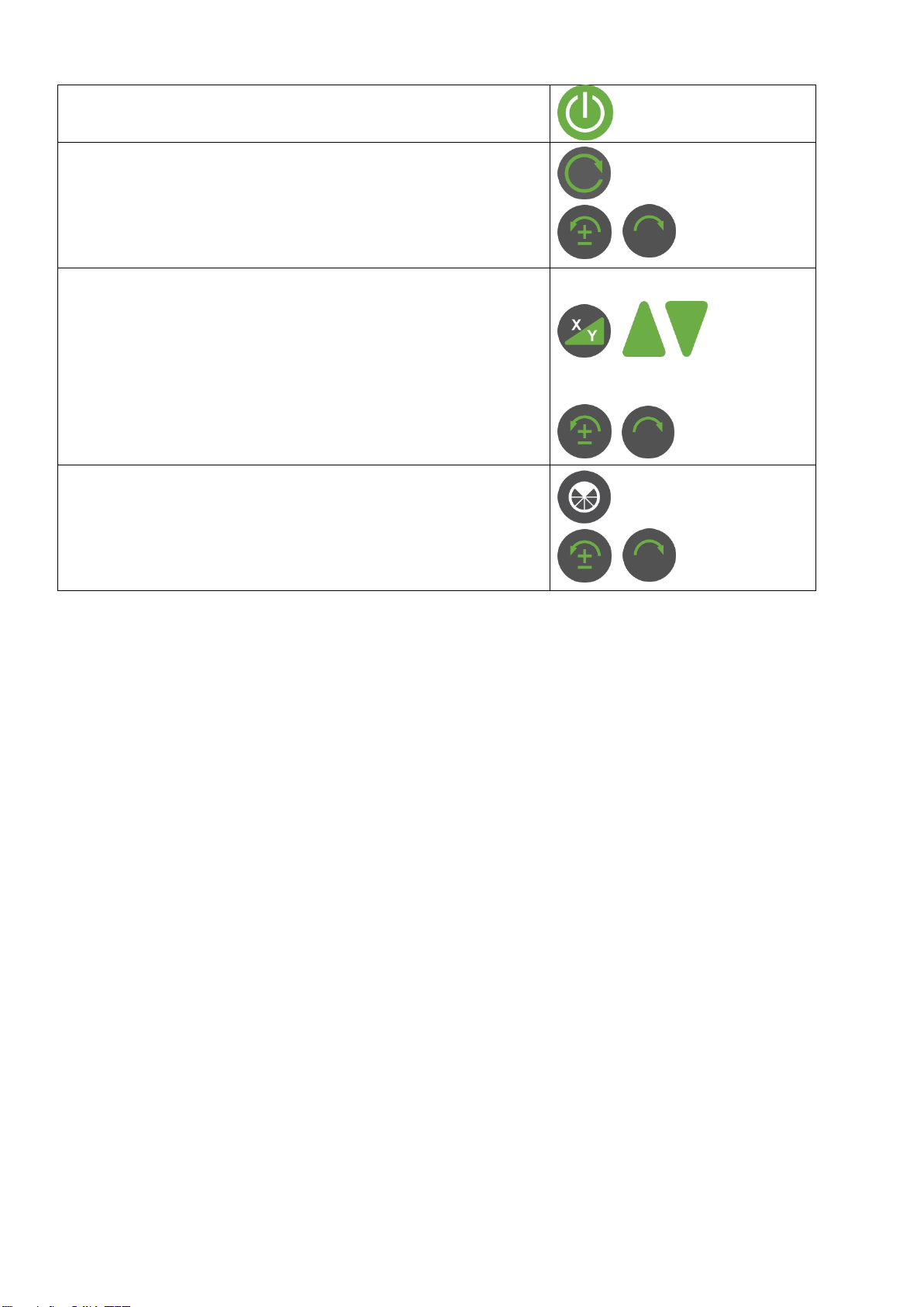
Brief Instructions15.
Switch on/off
Manual mode (press for 5 sec.)
Speed On/ Off
5 steps: 0 - 1000
Traversing the laser beam (step mode)
Slope
Display of last input
Input X
Input Y
Confirmation
Change sign and digits
Mask mode
Activation of 90 to 270°: Deactivation
Positioning the mask area

15
Technical Data16.
Laser
Laser Class / High Power
3R
Wavelength
635 -660nm
Output Power / High Power
< 5mW
Range
Up to 1000 m
Self-levelling range
± 5°
Levelling precision 3,4
± 1,5 mm / 30 m
Grade accuracy 3,4,5
0,025 % to 5% Grade
Slope X,Y
± 15%
Speed
0 –1000 RPM, 5-step, counterclockwise/
clockwise rotation in step mode.
Mask mode
90 - 270° and positionable
Power supply
NiMH+ 4x 1.2 V, 8Ah
or 4x 1.5V alkaline mono-cells
Running time rechargeable
battery/battery 2,3
≈ 70h / 120h
Charging time
≈ 6h
Working temperature
-15 to + 60°C
System of protection
IP 67 waterproof
Weight
≈ 3 kg
Radio remote control
Range 1,2,3
≈ 200 m
1) Under optimum atmospheric conditions.
2) Under optimum conditions
3) At 20°C
4) Parallel to the main X, Y axes
5) Without lateral slope

16
Supplier Declaration/Safety Information17.
The device complies with European Directives:
2004/108/EG, RTTE 1999/5/EG sowie 2011/65/EU
Harmonized standards:
EN 60950-1, EN 61000-6-3, EN301489-1, EN300220-1 V2.4.1,
EN 61000-6-2, EN301489-3 und EN300220-2 V2.4.1
A safety information plate is on the left-hand side of the device
An embedded Class 3B laser is installed. This means that
when you open the device there is a possibility of entering the
range of power values that are higher than Class 3R. Do not
point the laser at people. Do not look into the laser beam even
with optical instruments.
There are no parts to maintain or adjust inside the device.
Servicing may only be carried out by authorized persons.
Safety regulations for
THEIS Class 3R HIGH-POWER LASER DEVICES
Users must observe BGVB2 (Accident Prevention Regulations for
Laser Radiation in Germany).
Only trained personnel are allowed to operate this product to
avoid radiation with dangerous laser light.
The laser is subject to Class 3R
Do not remove the warning signs on the device!
Observe and secure the beam path over a large distance!
Never look into the laser beam or shine it into other peoples'
eyes! This also applies at a large distance from the device!
Always set up the laser such that people cannot be shone on
at eye level (pay attention to reflections).

17
Note:
This equipment has been tested and found to comply with the limits
for a Class B digital device, pursuant to part 15 of the FCC Rules.
These limits are designed to provide reasonable protection against
harmful interference in a residential installation. This equipment
generates, uses and can radiate radio frequency energy and, if not
installed and used in accordance with the instructions, may cause
harmful interference to radio communications. However, there is no
guarantee that interference will not occur in a particular installation.
If this equipment does cause harmful interference to radio or
television reception, which can be determined by turning the
equipment off and on, the user is encouraged to try to correct the
interference by one or more of the following measures:
Reorient or relocate the receiving antenna.
Increase the separation between the equipment and receiver.
Connect the equipment into an outlet on a circuit different from
that to which the receiver is connected.
Consult the dealer or an experienced radio/TV technician for
help.

18
Disposal18.
The surveying device, its accessories and packaging should be
recycled in an environmentally friendly way.
EU countries only:
Never put electrical tools in domestic refuse!
In accordance with EU directive 2012/19/EC concerning
Waste Electrical and Electronic Equipment and its
transposition into national legislation, measuring
equipment that can no longer be used must be collected
separately and recycled in an environmentally friendly
way. (WEEE - Reg. No. DE 10598800)
Rechargeable batteries:
Never put rechargeable batteries in domestic refuse, a fire or into
water. In accordance with Directive 2006/66EC, defective or spent
rechargeable batteries must be recycled or disposed of in an
environmentally friendly way.
EU countries only:
In accordance with Directive 2006/66EC, non-serviceable THEIS
laser devices or spent rechargeable batteries must be recycled or
can be returned directly to:
THEIS FEINWERKTECHNIK GMBH
Zum Bolzenbach 26
D- 35236 Breidenbach
+ 49 (0) 6465 - 67- 0
+ 49 (0) 6465 - 6725
info@theis-feinwerktechnik.de

19

20
Laser warning label for VISION High Power
Subject to changes
THEIS FEINWERKTECHNIK GMBH
35236 Breidenbach-Wolzhausen·Germany
22.01.2020
Table of contents
Other THEIS Measuring Instrument manuals


Popular Measuring Instrument manuals by other brands


Endress+Hauser
Endress+Hauser Liquiline System CA80HA Brief operating instructions

M&A INSTRUMENTS
M&A INSTRUMENTS CM8826FN Operation manuals

MFJ
MFJ MFJ-249C instruction manual

Excelitas Technologies
Excelitas Technologies OmniCure LM2011 Series user guide

Hanna Instruments
Hanna Instruments HI96716C instruction manual

Honeywell
Honeywell 6108 Operations & installation guide