3
1.5 Chemical Risk
▲WARNING
Lithium batteries are a chemical risk if misoperated,
mishandled or abused.
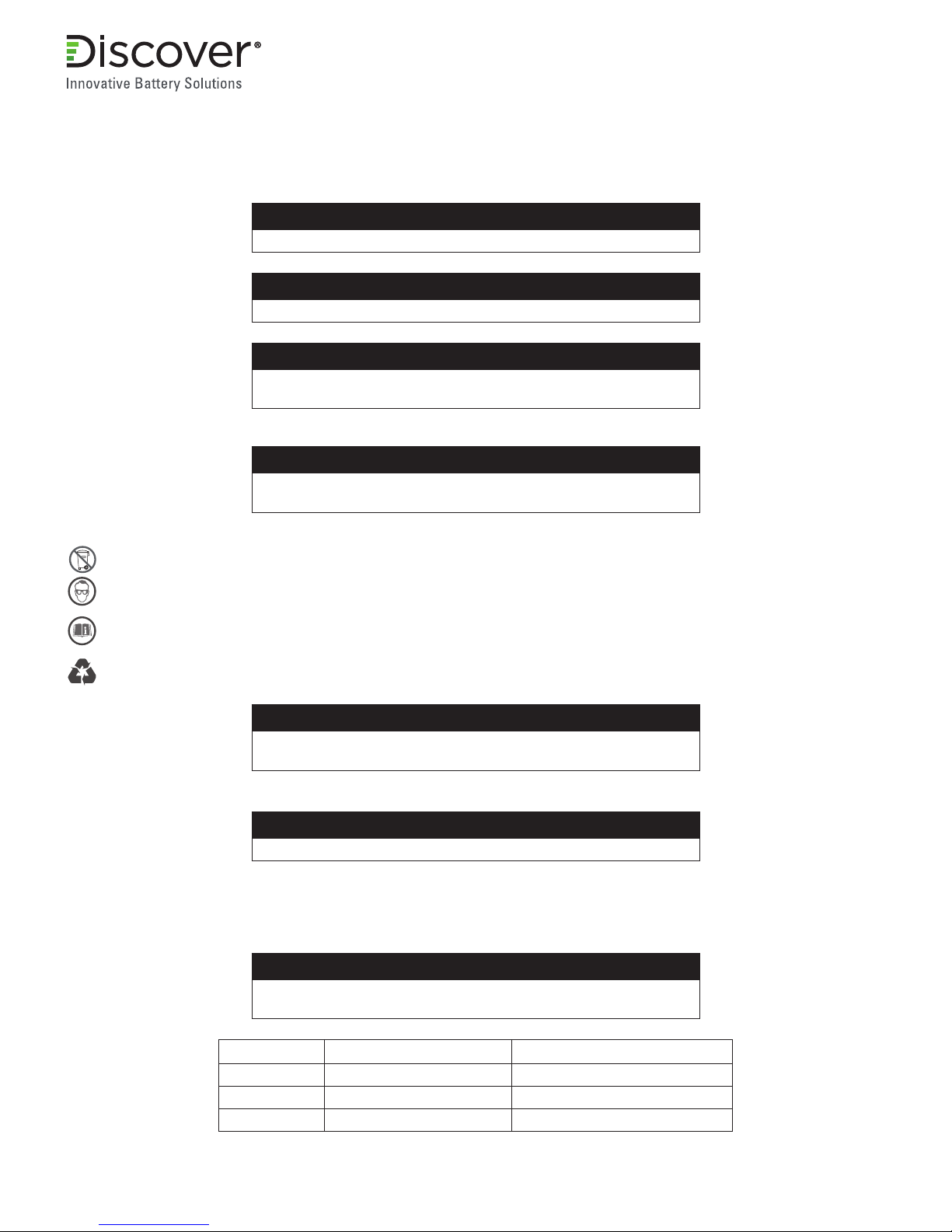
1.6 Do’s
• Do protect terminals from short circuit before, during, and after installation
• Do wear electrically insulated gloves
• Do use electrically insulated tools
• Do wear eye protection
• Do wear safety toe boots / shoes
• Do handle battery carefully
• Do secure battery safely
• Do always assume battery terminals are energized
1.7 Do Not’s
• Do not immerse battery in water
• Do not lift or carry the battery during usage or operation
• Do not operate or store battery outside of operating limits
• Do not short circuit battery
• Do not puncture battery
• Do not expose battery to ames, or incinerate
• Do not open battery case or dissemble battery
• Do not wear rings, watches, bracelets or necklaces when handling or working near battery
• Do not drop or crush battery
• Do not lift battery by the terminal cables
• Do not vibrate battery
• Do not expose battery to water or other uids
• Do not expose battery to direct sunlight
• Do not dispose of battery
• Do not connect with other types of batteries
• Do not expose battery to high temperatures
• Do not install with other battery types or brands
1.8 DC Motor Connection
Direct connection to DC motors, without proper safety protection including motor controllers, and external motor voltage clamping
systems (such as high power anti-parallel diodes or braking resistor systems), may result in damage to the internal battery
pack protection system which may result in unsafe situations. Please consult Discover Battery technical support before directly
connecting any motor loads.
1.9 Transportation
If the battery is not installed in equipment, it must be transported in the original package or equivalent.
Batteries are tested according to UN Handbook of Tests and Criteria, part III, sub section 38.3 (ST/SG/AC. 10/11/Rev.5). For
transport the batteries belong to category UN3480, Class 9, Packaging Group II.
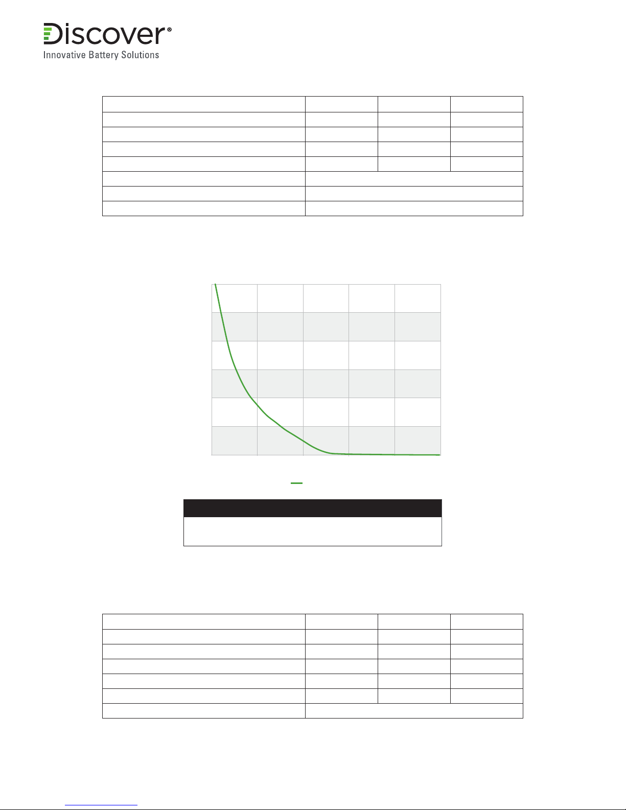
2. Battery Operating Limits
2.1 Maximum Battery Operating Limits
The battery should not be operated outside the Maximum Operating Limits, the BMS will open its internal relay and disconnect
the battery if any of the following limits are exceeded.