5
• Do not short circuit a battery or allow metallic conductive objects to
contact battery terminals.
• Replace the battery only with another battery that has been qualified
for the system.The use of an unqualified battery may present a risk of
fire, explosion, leakage, or other hazards.
• Avoid dropping the device or battery. If the device or battery is
dropped, especially on a hard surface, and the user suspects damage,
take it to a service center for inspection.
1.4 Personal Protective Equipment
• Use Personal Protective Equipment, including clothing, glasses,
insulated gloves, and boots.
• Do not wear rings, watches, bracelets, or necklaces when handling or
working near the battery.
2. SPECIFICATIONS
Specifications are published at 25oC / 77oF
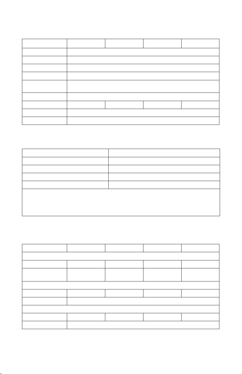
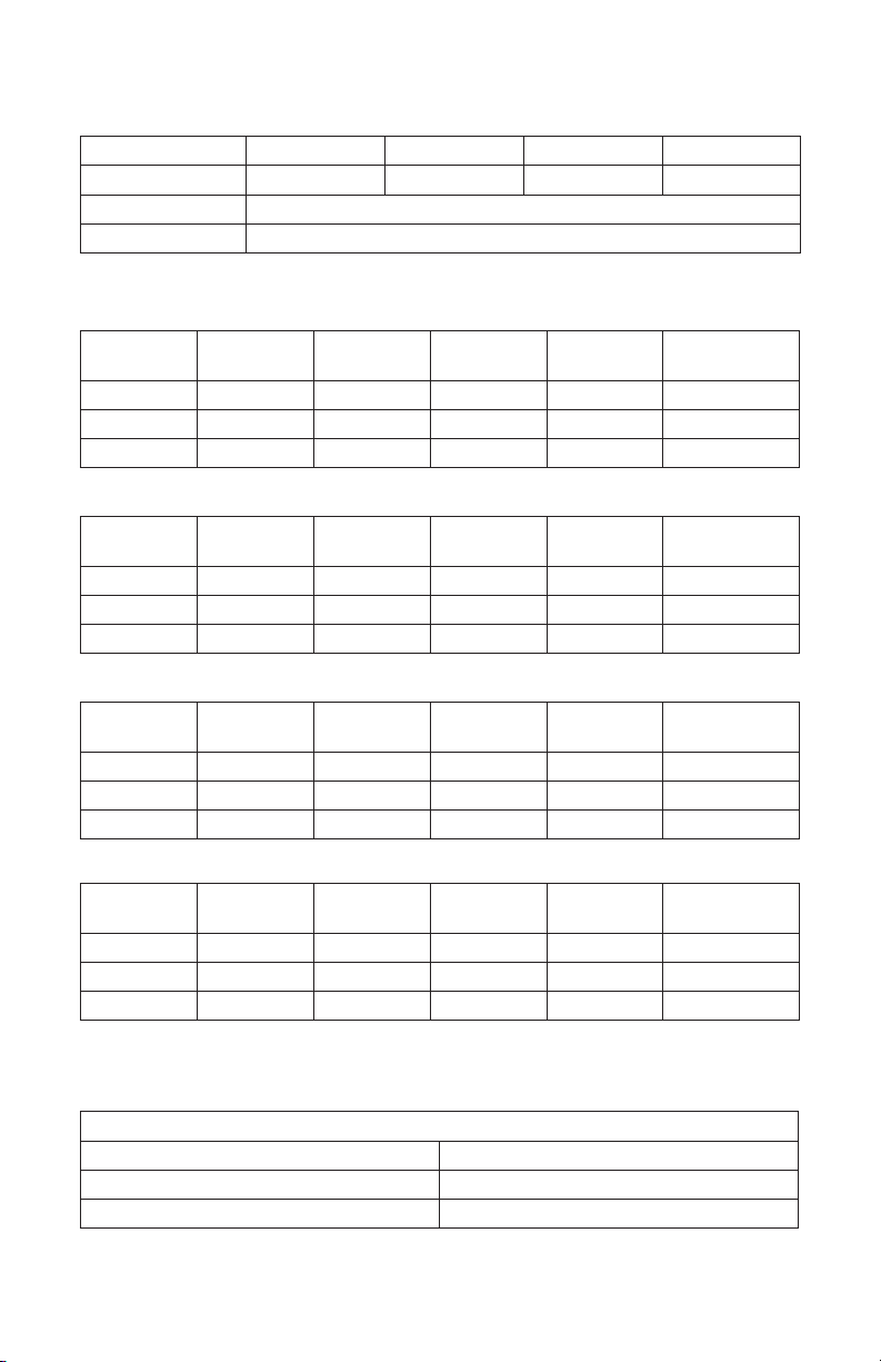
2.1 Electrical Specifications
Table 2-1. DLP-GC2 Electrical Specifications
Electrical Spec DLP-GC2-12V DLP-GC2-24V DLP-GC2-36V DLP-GC2-48V
Nominal Voltage 12.8 V 25.6 V 38.4 V 51.2 V
Energy 1536 Wh 1536 Wh 1152 Wh 1536 Wh
Capacity 1Hr 120 Ah 60 Ah 30 Ah 30 Ah
Reserve Capacity 25A
288 minutes 144 minutes 72 minutes 72 minutes
Charge Bulk Voltage - Bulk VDC 13.8 - 14.2 V 27.6 - 28.4 V 41.4 - 42.6 V 55.2 - 56.8 V
Charge Absorption Voltage - U1 MAX 13.8 V 27.6 V 41.4 V 55.2 V
Charge Float Voltage - U2 13.6 V 27.2 V 40.8 V 53.6 V
ChargeTermination Current
a
3.00 A 1.50 A 0.75 A 0.75 A
Low Voltage Disconnect Recommended 12.0 V 24.0 V 36.0 V 48.0 V
Low Voltage Disconnect 10.0 V 20.0 V 30.0 V 40.0 V
Max. Continuous Discharge Current 200 A 120 A 60 A 60 A
Nominal Charge Current 120 A 60 A 30 A 30 A
Max. Continuous Charge Current 120 A 60 A 30 A 30 A
Peak Discharge Current (3 seconds) 360 A RMS 180 A RMS 90 A RMS 90 A RMS
Fuse 200 A 125 A 60 A 60 A
Maximum Load Input Capacitance 49 mF 106 mF 51 mF 23 mF
a
Charge current termination is permitted to be less than specified. Note: when the charger termination current is
lowered, the internal balancing function will have more time to operate.