DISCOVER LITHIUM BLUE Premium Series User manual

1
INSTALLATION AND
OPERATION MANUAL
805-0010 REV D
A A
B B
C C
D D
E E
F F
G G
H H
J J
K K
L L
M M
N N
P P
R R
T T
24
24
23
23
22
22
21
21
20
20
19
19
18
18
17
17
16
16
15
15
14
14
13
13
12
12
11
11
10
10
9
9
8
8
7
7
6
6
5
5
4
4
3
3
2
2
1
1
DRAWN
CHK'D
APPV'D
MFG
Q.A
UNLESS OTHERWISE SPECIFIED:
DIMENSIONS ARE IN MILLIMETERS
SURFACE FINISH:
TOLERANCES:
LINEAR:
ANGULAR:
FINISH:
DEBURR AND
BREAK SHARP
EDGES
NAME
SIGNATURE
DATE
MATERIAL:
DO NOT SCALE DRAWING
REVISION
TITLE:
DWG NO.
SCALE:1:1
SHEET 1 OF 1
A0
WEIGHT:
DL_L3_Covers
A A
D D
N N
R R
DRAWN
PREMIUM SERIES
BATTERY MODELS
DLB-G24-12V
DLB-G24-24V
DLB-G24-36V
DLB-GC12-12V
DLB-GC12-24V

2
1. Audience, Safety, Messages, and Warnings 3
1.1 Audience 3
1.2 Safety, Messages, and Warnings 3
2. Specifications 5
2.1 Electrical Specifications 5
2.2 Mechanical Specifications 6
2.3 Environmental Specifications 6
2.4 Protection Specifications 6
2.5 Specifications for System Sizing 7
2.6 Regulatory 8
3.Transportation 8
4. Handling 8
5. Design and Features 9
5.1 Battery Management System Protections 9
5.2 Battery Fuse 10
5.3 Battery Management System Low Power Hibernation 10
5.4 Battery Management System Bluetooth Communications 10
5.5 Ingress Protection IP67 10
5.6 Membrane Vent 11
6. Installation 11
6.1Tools 11
6.2 Location 11
6.3 DC Cables 12
6.4 DC Protection 12
6.5Terminal Connections and Hardware 13
6.6 Single Battery Installation Procedure 14
6.7 Parallel Battery Installation Procedure 14
7. Operation 17
7.1 Low Voltage Cut-Off 17
7.2 BMS Hibernation 17
7.3 State of Charge 17
7.4 Charging 18
7.4.1 When to Charge the Battery 18
7.4.2 What to Charge the Battery with 18
7.4.3 Charging with a Lead-Acid Charger 19
7.4.4 Charging with Alternators 19
7.5 Charging Profile 19
7.5.1 Bulk Charge 20
7.5.2 Absorption Charge 20
7.5.3 Equalization Charge 21
7.5.4 Float Charge 21
8. Bluetooth 21
9. Routine Inspection 21
10. Replacing the Fuse 21
11. Storage 22
12. Related Information 23
13. Glossary ofTerms, Abbreviations, and Acronyms 23

3
WARNING
Important information regarding hazardous conditions that may result in personal
injury or death.
CAUTION
Important information regarding hazardous conditions that may result in personal injury.
NOTICE
Important information regarding conditions that may result in damage to the
equipment, but not personal injury.
1. AUDIENCE, SAFETY, MESSAGES AND WARNINGS
1.1 Audience
Certain configuration, installations, service, and operating tasks should only
be performed by qualified personnel in consultation with local utilities and/
or authorized dealers. Qualified personnel should have training, knowledge,
and experience in:
• Installing electrical equipment
• Applying applicable installation codes
• Analyzing and reducing hazards involved in performing electrical work
• Installing and configuring batteries
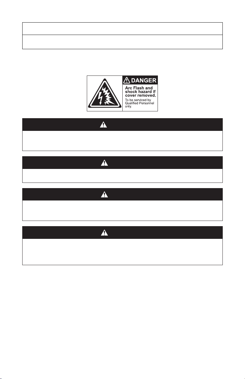
1.2 Safety, Messages and Warnings
• Do not disassemble, open, crush, bend, deform, puncture or shred.
• Do not modify, re-manufacture attempt to insert foreign objects into
the battery, immerse or expose to water or other liquids, expose to
fire, explosion or other hazards.
• Only use the battery for the system for which it is specified.
• Do not lift or carry the battery while in operation.
• Only lift, move, or mount in accordance with local regulations.
• Take care when handling battery terminals and cabling.
• Only use the battery with a charging system that has been qualified for
the system.The use of an unqualified battery or charger may present a
risk of fire, explosion, leakage, or other hazards.
• Do not short circuit a battery or allow metallic conductive objects to
contact battery terminals.
• Replace the battery only with another battery that has been qualified
for the system.The use of an unqualified battery may present a risk of
fire, explosion, leakage, or other hazards.
• Promptly dispose or recycle used batteries in accordance with local
regulations.
• Avoid dropping the device or battery. If the device or battery is
dropped, especially on a hard surface, and the user suspects damage,
take it to a service center for inspection.

4
NOTE
Ad hoc information concerning important procedures and features of the battery
not related to personal injury or equipment damage.
Before using the battery, read all instructions and cautionary markings on
the unit and all appropriate sections of this manual.
WARNING
This equipment must only be installed as specified. Do not disassemble or modify the
battery. If the battery case has been damaged, do not touch exposed contents. No
user-serviceable parts inside. Failure to follow these instructions may result in injury.
WARNING
CHEMICAL HAZARD: Do not touch the exposed contents of a Lithium cell. Failure to
follow these instructions may result in death or serious injury
CAUTION
FIRE AND BURN HAZARD: Do not cover or obstruct the heat sink or install the battery
in a zero-clearance compartment. Compartment ventilation is required.
Failure to follow these instructions can result in minor to moderate injury.
CAUTION
ELECTRIC SHOCK: Do not touch the energized surfaces of any electrical component in
the battery system. Before servicing the battery, follow all procedures to fully de-ener-
gize the battery system and use safe handling procedures when handling the battery.
Failure to follow these instructions may result in injury.

5
2. SPECIFICATIONS
Specifications are published at 25oC / 77oF
2.1 Electrical Specifications
Table 2-1. DLB Electrical Specifications
Electrical Spec DLB-G24-12V DLB-G24-24V DLB-G24-36V DLB-GC12-12V DLB-GC12-24V
Nominal Voltage 12.8 V 25.6 V 38.4 V 12.8 V 25.6 V
Energy 1280 Wh 1167 Wh 1167 Wh 2560 Wh 2560 Wh
Capacity 1Hr 100 Ah 45.6 Ah 30.4 Ah 200 Ah 100 Ah
Reserve Capacity 25A
240 minutes 120 minutes 76 minutes 480 minutes 240 minutes
Charge Bulk Voltage -
Bulk VDC 13.8 - 14.2 V 27.6 - 28.4 V 41.4 - 42.6 V 13.8 - 14.2 V 27.6 - 28.4 V
Charge Absorption
Voltage - U1 MAX 13.8 V 27.6 V 41.4 V 13.8 V 27.6 V
Charge Float Voltage - U2 13.6 V 27.2 V 40.8 V 13.6 V 27.2 V
ChargeTermination
Current
a
2.5 A 1.15 A 0.75 A 5 A 2.5 A
Low Voltage Disconnect
Voltage 12 V 24 V 36 V 12 V 24 V
Max. Continuous
Discharge Current 10 0 A 45 A 30 A 150 A 100 A
Nominal Charge Current 50 A 22.5 A 15 A 100 A 50 A
Max. Continuous
Charge Current 100 A 45 A 30 A 150 A 100 A
Peak Discharge Current
(2 seconds) 250 A 120A 120 A 250 A 250 A
Fuse 200 A 75 A 75 A 200 A 200 A
a
Charge current termination is permitted to be less than specified. When the charger termination current is lowered
the internal balancing function has more time to operate.
CAUTION: Hot Surfaces. Do not touch when hot.
CAUTION: Heavy Object. When lifting, follow appropriate
standards.
Do not dispose of the battery in the garbage. Do not dispose of
the battery in fire.
Use personal protective equipment when working with batteries.
Additional information concerning important procedures and
features of the battery. Read all the instructions before installation,
operation, and maintenance.
This product must be recycled and is made of recyclable materials.

6
2.2 Mechanical Specifications
Table 2-2. DLB Mechanical Specifications
Mechanical Spec. DLB-G24-12V DLB-G24-24V DLB-G24-36V DLB-GC12-12V DLB-GC12-24V
Chemistry LiFePO4
Length 262 mm (10.3 in) 312 mm (12.2 in)
Width 175 mm (6.9 in) 177 mm (7.0 in)
Height 210 mm (8.3 in) 276 mm (10.8 in)
Terminal SAE 5/16” stud terminal
TerminalTorque 13 Nm (9.6 ft-lb)
Weight 11.5kg (25.3lb) 20kg (44.1lb)
IP Rating IP 67
Case Material UL94-VO PBT/PC
2.3 Environmental Specifications
Table 2-3. DLB Environmental Specifications
Environmental Spec. All Models
ChargeTemperature
a
0°C to 55°C (32°F to 131°F)
Discharge Temperature
a
-20°C to 60°C (-4°F to 140°F)
StorageTemperature (1 month)
b
-20°C to 45°C (-4°F to 113°F)
StorageTemperature (6 months)
b
-10°C to 30°C (-14°F to 86°F)
a
This is the specified temperature of the cells, and not ambient. Ambient temperature and cell temperature may not
be the same.
b
Storage outside of specified temperatures will result in permanent capacity loss and invalidate the warranty.
2.4 Protection Specifications
Table 2-4. DLB Protection Specifications
Protection Spec. DLB-G24-12V DLB-G24-24V DLB-G24-36V DLB-GC12-12V DLB-GC12-24V
Overvoltage
Protection
a
> 14.6 V for
1 second
> 29.2 V for
1 second
> 43.8 V for
1 second
> 14.6 V for
1 second
> 29.2 V for
1 second
Recovery
a
< 13.8 V for
5 seconds
< 27.6 V for
5 seconds
< 41.4 V for
5 seconds
< 13.8 V for
5 seconds
< 27.6 V for
5 seconds
Overvoltage
Hibernation 3 Consecutive overvoltage protections. Discharge battery to recover.
Undervoltage
Protection
b
< 10 V for
3 seconds
< 20 V for
3 seconds
< 30 V for
3 seconds
< 10 V for
3 seconds
< 20 V for
3 seconds
Recovery
b
> 10.8 V for
1 second
> 21.6 V for
1 second
> 32.4 V for
1 second
> 10.8 V for
1 second
> 21.6 V for
1 second
Undervoltage
Hibernation 3 Consecutive undervoltage protections. Charge battery to recover.

7
Protection Spec. DLB-G24-12V DLB-G24-24V DLB-G24-36V DLB-GC12-12V DLB-GC12-24V
Overcurrent
Protection > 110 A for
2 seconds
> 49.5 A for
2 seconds
> 33 A for
2 seconds
> 160 A for
2 seconds
> 110 A for
2 seconds
Recovery 20 seconds after the load or charge is removed.
Over-temperature in Discharge
Protection
c
Cell temperature above 60°C (140°F).
Recovery
c
Cell temperature below 55°C (131°F) for 4 seconds.
Under-temperature Discharge
Protection
c
Cell temperature below -20°C (-4°F).
Recovery
c
Cell temperature above -15°C (5°F) for 4 seconds.
Over-temperature in Charge
Protection
c
Cell temperature above 55°C (131°F) and a charge is detected.
Recovery
c
Cell temperature below 50°C (122°F) for 4 seconds.
Under-temperature in Charge
Protection
c
Cell temperature below 0°C (32°F) and a charge is detected.
Recovery
c
Cell temperature above 5°C (41°F) for 4 seconds.
a
Overvoltage protection monitors individual cell voltages and will trigger with any cell over 3.65 VPC and recover
when all cells are below 3.45VPC. Nominal voltages are provided for guidance only.
b
Undervoltage protection monitors individual cell voltages and will trigger with any cell under 2.5 VPC and recover
when all cells are above 2.7VPC. Nominal voltages are provided for guidance only.
c
This is the specified temperature of the cells, and not ambient. Ambient temperature and cell temperature may not
be the same.
2.5 System Size Specifications
Table 2-5. DLB-G24-12V System Size Specifications
System Size
Specifications Peak Current Constant Current Energy / Usable
Capacity
Reserve Capacity
at 25A
1 Battery 250 A 100 A 1280 Wh 240 minutes
2 Battery 500 A 200 A 2560 Wh 480 minutes
3 Battery 750 A 300 A 3840 Wh 720 minutes
4 Battery 1000 A 400 A 5120 Wh 960 minutes
Table 2-6. DLB-G24-24V System Size Specifications
System Size
Specifications Peak Current Constant Current Energy / Usable
Capacity
Reserve Capacity
at 25A
1 Battery 120 A 45 A 1167 Wh 120 minutes
2 Battery 240 A 90 A 2334 Wh 240 minutes
3 Battery 360 A 135 A 3501 Wh 360 minutes
4 Battery 480 A 180 A 4668 Wh 480 minutes

8
Table 2-7. DLB-G24-36V System Size Specifications
System Size
Specifications Peak Current Constant Current Energy / Usable
Capacity
Reserve Capacity
at 25A
1 Battery 120 A 30 A 1167 Wh 76 minutes
2 Battery 240 A 60 A 2334 Wh 152 minutes
3 Battery 360 A 90 A 3501 Wh 228 minutes
4 Battery 480 A 120 A 4668 Wh 304 minutes
Table 2-8. DLB-GC12-12V System Size Specifications
System Size
Specifications Peak Current Constant Current Energy / Usable
Capacity
Reserve Capacity
at 25A
1 Battery 250 A 150 A 2560 Wh 480 minutes
2 Battery 500 A 300 A 5120 Wh 960 minutes
3 Battery 750 A 450 A 7680 Wh 1440 minutes
4 Battery 1000 A 600 A 10240 Wh 1920 minutes
Table 2-9. DLB-GC12-24V System Size Specifications
System Size
Specifications Peak Current Constant Current Energy / Usable
Capacity
Reserve Capacity
at 25A
1 Battery 250 A 100 A 2560 Wh 240 minutes
2 Battery 500 A 200 A 5120 Wh 480 minutes
3 Battery 750 A 300 A 7680 Wh 720 minutes
4 Battery 1000 A 400 A 10240 Wh 960 minutes
2.6 Regulatory
Table 2-10. DLB Regulatory
DLB Regulatory All Models
Transportation UN38.3
EMC EN 61000-6-1: 2007
3. TRANSPORTATION
If the battery is not installed in equipment, it must be transported in the
original package or equivalent. Batteries are tested according to the UN
Handbook ofTests and Criteria, part III, subsection 38.3 (ST/SG/AC. 10/11/
Rev. 5). For transport, the batteries belong to category UN3480, Class 9.
4. HANDLING
Prior to handling:
• Keep the battery away from sparks and flames
• Battery cables must be disconnected
• Battery terminals must be protected from short-circuiting and touch
• A battery handle must be used to lift the battery
• Do not lift or carry the battery while it is in use or operation
• Do not lift the battery by the attached battery cable

9
5. DESIGN AND FEATURES
Item Description
1The heat sink of the Battery
Management System (BMS)
2
Battery terminal covers,
positive cover (+/red), negative
cover (-/black)
3Battery negative ( - ) 5/16"
terminal stud
4Battery positive ( + )5/16"
terminal stud
5 Handle
6 Fuse
7 Battery hold-down
8 PTFE membrane vent
5.1 Battery Management System Protections
The Battery Management System's (BMS) primary function is to monitor
cell module voltage and temperature, and battery current.The BMS
uses this information to maintain cell operation within specification. If a
parameter falls outside of operating specifications the BMS will disconnect
and protect the battery from:
1. Over voltage. Over voltage protection occurs when charge voltages are
too high.
2. Under voltage. Under voltage protection occurs during discharge when
the voltage is discharged too low.
3. Over-current. Over-current protection can occur during charge or
discharge.This may happen when powering up a load (short and high
inrush current) or during sustained currents above specified limits.
4. Over-temperature. Over-temperature protection can occur during charge
and discharge.
5. Under-temperature. Under-temperature protection can occur during
charge and discharge.
Refer to Table 2-4. DLB Protection Specifications for trigger and recovery values.
The BMS will reconnect when recovery thresholds are met. If the BMS
disconnects due to low voltage protection, the loads must be removed
before the BMS will be able to reconnect. If the system has a constant
parasitic draw a physical disconnect switch is recommended to aid in
reconnecting the battery.
1
2
6
5
3
4
8
7
7
Figure 1. Battery Features.

10
NOTE
Charge and discharge have different operating temperature limits.
NOTE
If the BMS disconnects responding to temperature or current limits, wait for the
temperature or current to reach normal operating limits.
5.2 Battery Fuse
The Battery fuse is intended to protect the electronic components of the
Battery's internal BMS from a high externally generated current. Fuses are
relatively inexpensive and easy to replace in the field, as compared with the
BMS which is a high-cost item to replace.
NOTE
Additional external DC fusing is required to protect the battery cables from DC over-
current and to meet installation codes.
5.3 Battery Management System Low Power Hibernation
After 10 continuous minutes of < 300 mA charge or discharge activity, the
battery will enter hibernation mode reducing the consumption of energy
from the BMS and Bluetooth communications to minimum levels.The
internal relay will open and disconnect terminals.
NOTE
Residual voltage may be still be detected at the terminals when the battery is in Low
Power Hibernation mode.
5.4 Battery Management System Bluetooth Communications
The BMS communicates important battery operating information such as the
State of Charge, voltage, operating current, temperature, and diagnostic logs
via Bluetooth communications to devices such as mobile phones and tablets.
Battery data is then viewable using the Lithium Blue Battery Monitor App, which
is either downloaded from the Apple Store or Google Play Store. Bluetooth
communication is not available when the battery is in Low Power Hibernation.
5.5 Ingress Protection IP67
Ingress protection rates the degree of protection provided by mechanical
casings and electrical enclosures against intrusion, dust, accidental contact,
and water under specified conditions.The IP67 rating includes testing that
indicates no ingress of dust particles and no ingress of a harmful quantity of
water when immersed for up to 30 minutes.
IP codes provide guidance on suitability for use under different environmental
conditions. IP ratings do not indicate fitness for purpose or confer a performance
guarantee.

11
5.6 Membrane Vent
Membrane vents enable the free passage of gases and vapors and allow
for the equalization of the pressure between the internal case and ambient
conditions.This helps to protect and preserve the internal components of the
battery.
6. INSTALLATION
WARNING
ELECTRIC SHOCK AND FIRE HAZARD: This equipment must only be installed as
specified. Do not disassemble or modify the battery. If the battery case has been
damaged, do not touch exposed contents. No user-serviceable parts inside.
Failure to follow these instructions may result in injury.
CAUTION
FIRE AND BURN HAZARD: Do not cover or obstruct the heat sink or install the battery in
a zero-clearance compartment. Compartment ventilation is required.
Failure to follow these instructions can result in minor to moderate injury.
NOTE
It is the responsibility of the installer to ensure that all applicable installation
requirements and standards are met.
6.1 Tools
• Insulated tools sized to match nuts, bolts, and cables in use
• RMS type Voltmeter
• Post cleaner and wire brush
• Personal protective equipment
6.2 Location
The battery should be installed in locations that meet the following requirements:
1. Do not install in direct sunlight. Avoid installing the battery in an area
with high ambient temperature.
2. Moderate temperatures. Ambient temperatures of 15°C to 20°C (59°F
to 68°F) are ideal for extending LiFePO4battery life. Do not install in the
Engine Bay as this will expose the battery to elevated temperatures
greater than 40°C (104°F).
3. Ventilated. Do not install in zero-clearance compartments. Maintain at
least 50 mm (2 inches) above the top cover for open airflow.
4. Proper orientation. The battery may be installed in any orientation
other than upside down. Do not install upside down.
5. Hold-downs. The battery is designed with standard B1/B3 hold-down
ledges for use with standard battery trays.The battery may also be
strapped in place with over-the-top holds.

12
6. Minimum cable lengths. Select a location that minimizes the length of
battery cables in order to reduce voltage drop from impedance leading
to reduced performance.
NOTICE
Only a non-conductive material that covers less than 20% of the heat sink for 'over the
top' hold-downs may be used.
NOTE
Warranty will be void if operated outside of these conditions.
6.3 DC Cables
CAUTION
FIRE HAZARD: Undersized cables can become hot and may potentially catch fire.
Failure to follow these instructions can result in minor to moderate injury.
The DC battery cables should meet the following requirements:
1. Copper-stranded cable. DC cables must be stranded, copper, and must
be rated 90 °C minimum.The cables must be terminated with lugs that
fit the DC terminals snugly.
2. Minimum cable lengths. Select a location that minimizes the length of
battery cables in order to reduce voltage drop from impedance leading
to reduced performance.
3. Appropriate cable gauge. The cables should be capable of carrying the
normally expected current, plus a margin of safety.
4. Proper polarity. Positive ( + ) connected to positive ( + ), and negative ( - )
connected to ( - ).
6.4 DC Protection
CAUTION
FIRE HAZARD: Undersized fuses and disconnects may become overloaded and
potentially cause a fire. Fuses and disconnects and are required to open before the
cable reaches its maximum current carrying capability.
Failure to follow these instructions can result in minor to moderate injury.
To protect the system and DC battery cables, additional DC over-current
protection and a DC disconnect switch are required.
1. Appropriate size. Fuses and disconnects must be sized in accordance
with local codes to protect the wiring in the system and are required to
open before the cable reaches its maximum current carrying capability.
1. Install protection in the positive cable.The fuse and disconnect should
be located as close as possible to the battery and must be installed in

13
the positive cable. Applicable codes may limit how far the protection
can be from the battery.
NOTE
AC circuit breakers and DC circuit breakers are not interchangeable. Check the label on
the circuit breaker to ensure it is the correct type and rating. Use only DC circuit breakers.
NOTE
Local electrical code in your area may require both positive and negative DC disconnect
switches. Always refer to the applicable code and check with the authority having
jurisdiction to confirm local requirements.
6.5 Terminal Connections and Hardware
The terminal connections and hardware should meet the following requirements:
1. Connect to the battery terminal. Do not connect the cable lug to the fuse
post. All cable lugs must be in direct contact with the battery terminal
deck. Do not put washers between the terminal deck and cable lug.
2. Use the proper torque. Use a torque wrench to properly adjust terminal
hardware torque. Periodically check to ensure torque is correct.
Battery
Cable Lug
Figure 2. Correct Installation.
Fuse
Figure 3. Incorrect Installation.
NOTICE
Failure to properly torque battery terminal nuts may increase resistance and lower voltage
which may lead to burnout of the terminals and void the warranty.

14
6.6 Single Battery Installation Procedure
CAUTION
FIRE HAZARD: Undersized cables can become hot and may potentially catch fire.
Failure to follow these instructions can result in minor to moderate injury.
Battery cables (battery to load and/or battery to charger) must meet the following
requirements to optimize performance:
1. Minimum cable lengths. Select a location that minimizes the length of
battery cables in order to reduce voltage drop from the impedance.
Equipment must be installed in accordance with the standards set by the local
authority having jurisdiction
1. If the circuit of equipment that the battery is installed in has a
disconnect, open the disconnect to isolate the battery.
2. Ensure the cable connections are clean and serviceable.
3. Install and secure the battery. Be careful not to make contact between
the terminals and any metal mounting, fixture, or body part.
4. Connect battery cables taking care to connect the positive ( + ) cable
to the positive ( + ) terminal. Connect negative ( - ) cable last to avoid
sparks. Short circuits may damage the battery and this will void the
warranty.
5. Torque all battery terminals to the recommended terminal torque of 13
Nm (9.6 ft-lb) to secure cable lugs.
6. Close circuit disconnect (if open).
NOTICE
Failure to torque up to specifications may increase resistance and lower voltage
and may lead to burnout of the terminals and invalidate the warranty.
6.7 Parallel Battery Installation Procedure
CAUTION
FIRE HAZARD: Undersized cables can become hot and may potentially catch fire.
Failure to follow these instructions can result in minor to moderate injury.
Batteries used in a parallel system must meet the following requirements:
1. Same model. Batteries must be the same model, age, capacity, and
voltage.
2. Equal voltage. Always ensure that batteries are within 50mV (0.05V) of
each other before installing them in parallel.

15
Battery cables (battery to load and/or battery to charger) must meet the following
requirements to optimize performance:
1. Minimum cable lengths. Select a location that minimizes the length of
battery cables in order to reduce voltage drop from the impedance.
Interconnection cables (battery to battery) must meet the following requirements
to optimize performance:
1. Equal cable gauge.The interconnection cables should be the same gauge.
2. Equal cable length. The interconnection cables should be of equal length.
Equipment must be installed in accordance with the standards set by the local
authority having jurisdiction.
1. If the circuit of equipment that the batteries are installed in has a
disconnect, open the disconnect to isolate the batteries.
2. Ensure the cable connections are clean and serviceable.
3. Install and secure new batteries. Be careful not to make contact
between the terminals and any metal mounting, fixture, or body part.
4. Connect battery positive ( + ) cables between the battery positive ( + )
terminals with snugly tightened terminal hardware.
Figure 4. Positive Parallel Connections.
5. Connect battery negative ( - ) cables between the battery negative ( - )
terminals with snugly tightened terminal hardware.
Figure 5. Negative Parallel Connections.

16
6. Connect the load positive ( + ) cable and load negative ( - ) cable to the
opposing ends of the parallel batteries.
LOAD (+)
LOAD (-)
Figure 6. Load Connections.
7. Connect the charger positive ( + ) cable and charger negative ( - ) cable
to the opposing ends of the parallel batteries.
LOAD (+)
LOAD (-)
CHARGER (-)
CHARGER (+)
Figure 7. Charger Connections.
8. Torque all battery terminals to the recommended terminal torque of 13
Nm (9.6 ft-lb) to secure cable lugs.
NOTICE
Failure to properly torque battery terminal nuts may increase resistance and lower voltage
which may lead to burnout of the terminals and void the warranty.
NOTE
Wherever replacing an old battery in a string, use a battery of the same age, model,
capacity, and voltage.
NOTE
Before installing the battery in parallel, ensure that each battery is charged to 100% SOC.

17
7. OPERATION
The Battery BMS prevents battery operation outside of specified operating
conditions. Make sure to understand each of these protections and how to set
up the system accordingly. Refer to Table 2-4. DLB Protection Specifications.
NOTICE
Intentional bypassing of the BMS to operate the battery outside maximum and
minimum limits voids warranty.
7.1 Low Voltage Cut-Off
The low voltage cut-off, as controlled by the application, should be programmed
at or above the LowVoltage Disconnect Voltage value given in Table 2-1. DLB
Electrical Specifications.This ensures that the load will disconnect before the BMS is
forced to enter low voltage protection.
NOTICE
Storing or leaving the battery at 0% SOC will lead to irreversible damage.
7.2 BMS Hibernation
The BMS will enter hibernation mode if there is no charge or discharge activity
detected for 10 minutes, or if the battery triggers low or high voltage protection
three consecutive times. During this time, the BMS will disconnect the internal
SSR and Bluetooth functions will be disabled.This protection helps safeguard the
battery from becoming over-discharged.
The battery will exit hibernation mode by:
• Applying a charge current. If the battery is in low voltage protection and
hibernation mode a small charge current will reactivate the BMS.
• Applying charge or discharge current. If the battery is not in low voltage
protection but is in hibernation mode a charge or discharge current will
activate the BMS.
7.3 State of Charge
A Bluetooth App for mobile devices provides real-time access to the battery state-
of-charge, voltage, operating current, temperature, status and a diagnostic report.
Search for Lithium Blue Battery Monitor App on Apple’s App Store or Google Play.
A voltage-based battery meter that is designed for lead-acid batteries will not
provide an accurate state of charge (SOC) for lithium. Use a battery meter that
measures current, rather than voltage, for lithium batteries.

18
7.4 Charging
Each electrical system will have different characteristics and balance-of-system
components. Modifications to charger settings may be required to optimize the
system performance of each.
NOTICE
Always confirm that the charging device is incapable of producing transient spikes
that exceed the published terminal voltage limits for the battery.
NOTICE
Never charge a visibly damaged or frozen battery.
NOTICE
Always confirm the charging curve meets the battery’s charging requirement.
7.4.1 When to Charge the Battery
• Opportunity charging is OK. Charging the battery after every use will
not reduce its cycle life.
• Partial state of charge is OK. If the battery SOC is greater than 10% at
the end of discharge, it does not require an immediate charge.
• Charge if below 10% SOC. If the battery has been discharged below
10% SOC it must be charged within 24 hours to avoid permanent
damage to the battery. Otherwise irreversible damage to the battery
cells will occur in a very short period of time.
• Low currents extend life. Charging at 50% of nominal current or lower
helps extend battery cycle life.
• Proper temperature. Ensure charging is within the charge temperatures
specified in Table 2-3 DLB Environmental Specifications.
NOTICE
The battery must be charged within 24 hours if it has been discharged below 10%
SOC. Otherwise irreversible damage to the battery cells will occur in a very short
period of time and the warranty will be invalid.
NOTICE
Charging the battery when it is below 0°C will cause irreversible damage and
invalidate the warranty.
7.4.2 What to Charge the Battery with
Use a Lithium LiFePO4charger. Use a charger with a dedicated LiFePO4
charging algorithm that matches the DLB charging profile and parameters.
For charging parameters refer to Table 2-1. DLB Electrical Specifications and Figure 8
DLB Charge Graph.

19
7.4.3 Charging with a Lead-Acid Charger
CAUTION
FIRE AND BURN HAZARD: Do not perform an equalization charge on lithium batteries.
Failure to follow these instructions can result in minor to moderate injury.
• Not recommended. For the reasons stated below, it is not
recommended to use a lead-acid charger.
It is possible. Short-term charging with a lead-acid charger is possible only if
the bulk and absorption voltages are equal to or below the bulk voltage. Refer
to Table 2-1 DLB Electrical Specifications for charging parameters and Figure 8 DLB
Charge Graph.
• Gel profiles. GEL profiles are typically the lead-acid settings closest to
the recommended Lithium settings.
• No equalization. Do not perform an equalization charge on lithium
batteries.
• No temperature compensation. Temperature compensation must be
disabled.
NOTICE
Some lead-acid charge profiles are within the LiFePO4charging voltages, however
many will exceed the BMS high voltage protection limits.This will result in the
BMS disconnecting at the end of the charge cycle, likely causing the charger status
indicator to display an error.
7.4.4 Charging with Alternators
• Not recommended. For the reasons stated below, it is not
recommended to use an alternator as a charge source.
• It is possible. Charging with an alternator is possible. However, use
one of the following is REQUIRED:
• Voltage regulator, battery isolator, or DC/DC converter
NOTICE
If the alternator charge voltage or current is too high, the BMS will protect the battery
by disconnecting the battery from the system. In a one-battery system, a large voltage
spike may also be created, potentially damaging both the alternator and BMS.
NOTICE
LiFePO4batteries are so efficient the alternator may burn itself out over extended
periods of output at or close to peak current.
7.5 Charging Profile
DLB LiFePO4battery charging should include both Bulk and Absorption phases.
For charging parameters refer to Table 2-1. DLB Electrical Specifications.

20
NOTE
Charging at 50% of nominal current or lower will extend battery cycle life.
7.5.1 Bulk Charge
Bulk phase. The first phase of the charging process is the Bulk charge, also
referred to as the constant current phase.This is when the maximum amount
of current from the charger is directed to the battery until the desired voltage
is reached.The Bulk phase will recharge the battery to approximately 90%-
95% SOC.
If the charging source is a generator or other charge source that is not
efficient at low output current a single-stage charge may be appropriate. A
single-stage charge will only complete the Bulk phase portion of the charge
curve.This method should return the battery to between 90-95% SOC.
Refer to Table 2-1 DLB Electrical Specifications for charging parameters.
7.5.2 Absorption Charge
Absorption phase.The second phase of the charging process is Absorption
Charge, also referred to as the constant voltage phase.This is when the
charger reduces current accordingly to maintain the desired voltage.
Refer to Table 2-1 DLB Electrical Specifications for charging parameters.
100% SOC
Bulk Vdc
I Max
I Min 200 milliamps required
for balancing current
Terminate at 2% - 3% of
battery rated capacity
U1 Max
Absorption & Balancing
CURRENT
Absorption
Bulk
U2 Float
Float
Figure 8. Charge Graph.
This manual suits for next models
5
Table of contents
Other DISCOVER Camera Accessories manuals

DISCOVER
DISCOVER LITHIUM PRO PROFESSIONAL Series User manual

DISCOVER
DISCOVER 14-24-2800 User manual

DISCOVER
DISCOVER Tubular Gel OPzV User manual

DISCOVER
DISCOVER LYNK Edge Card Victron User manual

DISCOVER
DISCOVER 14-24-2800 User manual

DISCOVER
DISCOVER 15-24-1000 User manual

DISCOVER
DISCOVER 14-12-3000 User manual

DISCOVER
DISCOVER SOPzV User manual

DISCOVER
DISCOVER DRY CELL User manual

DISCOVER
DISCOVER Tubular Gel OPzV User manual