DiscreteHeat ThermaSkirt User manual
INSTALLATION
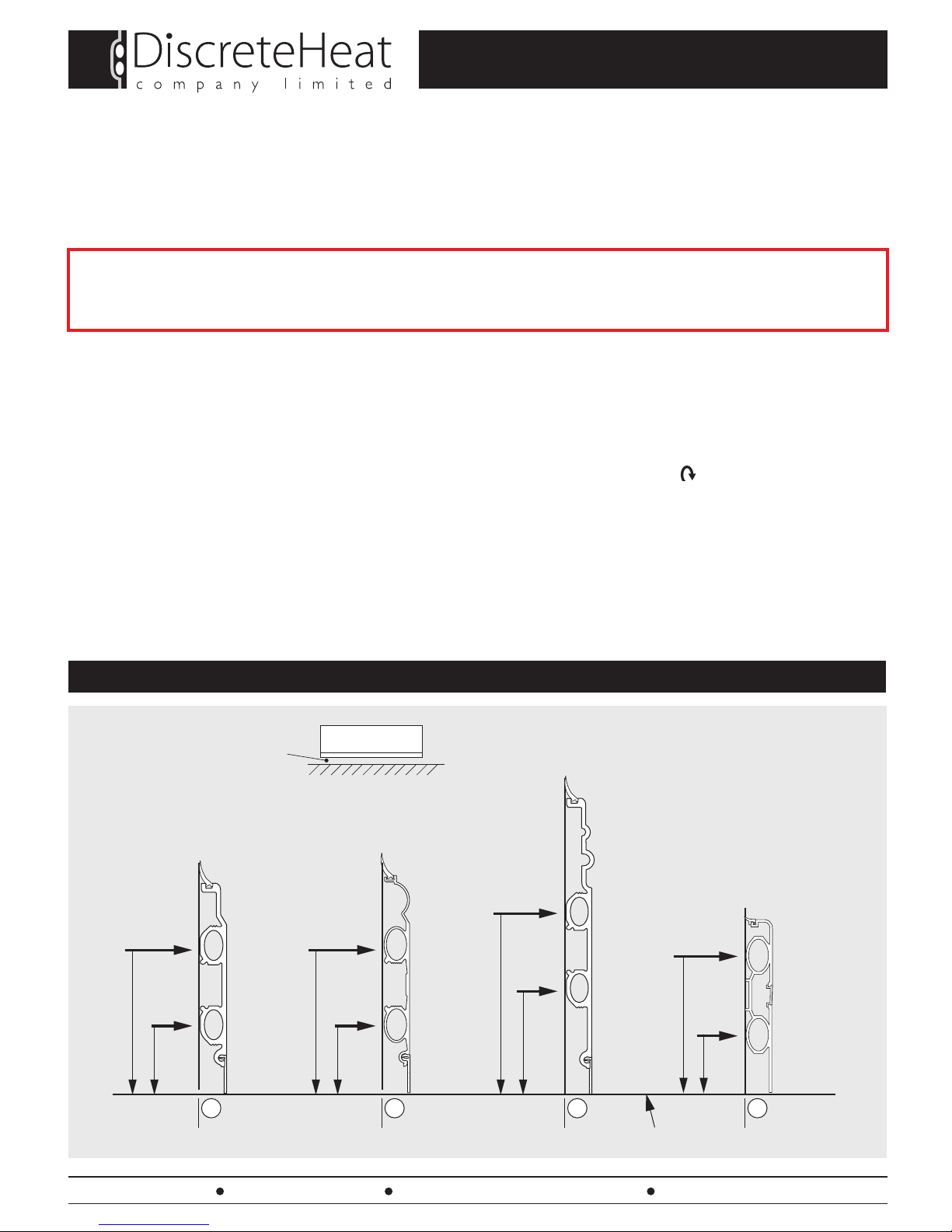
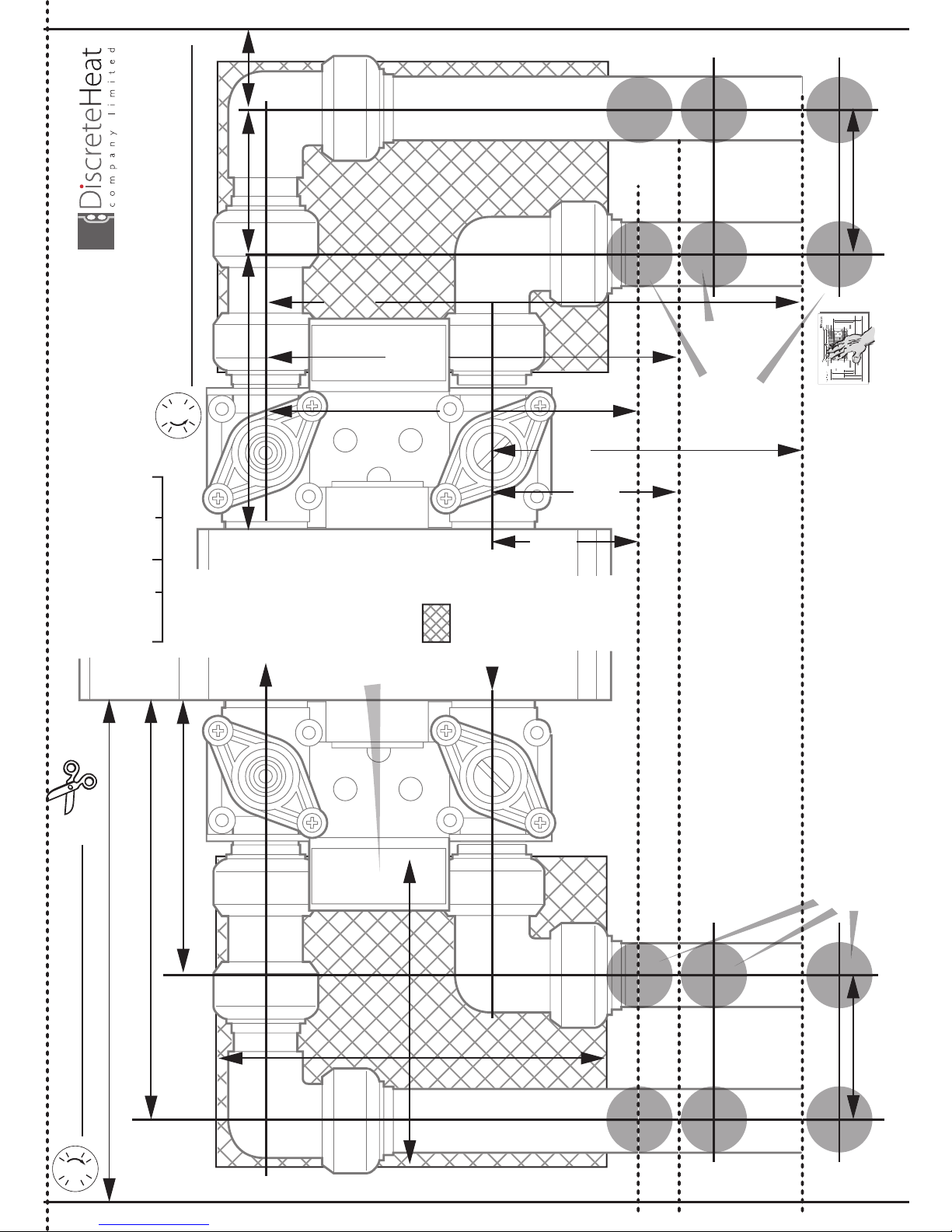
1. POSITION FEED PIPES
ThermaSkirt®
AN ECO REVOLUTION IN ROOM HEATING
Tel: 0845 1238367 Fax: 01942 665104 e-mail: info@discreteheat.co.uk web: www.discreteheat.co.uk
Page 1
TOOLS YOU WILL NEED:
A suitable metal cutting saw, preferably a chop saw (only if cutting lengths on site) / A DiscreteHeat rotary de-burring tool / An accurate
quality tape measure (Black & Decker, DeWalt etc.) / String line and chalk or laser level / A Stanley/sharp knife and/or plasterboard saw /
Power drill with hammer action / Power driver / Size 10 screws (50-100mm) / Plastic or timber faced mallet / Rawlplugs and\or plaster-
board fixings / Pipe cutting tool (15mm/16mm) /Various push fit connectors / Your plan and cutting list (if purchased as a room kit).
These instructions are intended as a guide only. Your installation & design may vary - if in doubt ask for help.
DiscreteHeat Co. Ltd. accept no liability for any errors or omissions.
FLOW
15/16mm
FLOW
15/16mm
FLOW
15/16mm
RETURN
15/16mm
RETURN
15/16mm
RETURN
15/16mm
45mm
100mm
URBAN LT
(6in / 150mm) DECO PR/BM
(4.5in / 115mm)
REGENCY OG
(8in / 200mm)
ISSUE 22 / January 2014 (Download further/latest copies at www.discreteheat.co.uk/technical.html)
TM
75mm
130mm
FINISHED FLOOR LEVEL
35mm
90mm
FLOW
15/16mm
RETURN
15/16mm
45mm
100mm
CLASSIC TS
(6in / 150mm)
THE SAME DIMENSIONS AND SPACINGS APPLY TO ANTI-CLOCKWISE INSTALLATIONS.
ALL EXAMPLES SHOWN ARE CLOCKWISE/RH INSTALLATIONS.
Remember to allow
for carpet or tiles if
NOT Finished Floor Level
Your ThermaSkirt system must be cleansed and protected by a corrosion inhibitor suitable for alluminium
radiators, as required by BS 7593:2006 ‘Code of Practice for treatment of water in domestic hot central heating
systems’. DiscreteHeat recommends our own TS3 Cleanser and TS5 Inhibitor or Scalemaster CM5 or CM10.
FAILURE TO PROTECT YOUR SYSTEM WILL INVALIDATE YOUR WARRANTY
DO Carefully check you have all the parts required by your design systems before you start cutting.
DO Check all skirting measurements twice before cutting: see diagram on page 2 (unless provided pre-cut).
DO Ensure that you use the templates (pages 9 - 12) to get your pipes correctly positioned.
DON’T
Forget to check the orientation and quantity of retaining clips for each connection and fitting before you insert into skirting - it varies!
DON’T Forget that the FEED and RETURN pipes need to be tight to the wall to ensure your covers fit correctly.
DON’T Forget that aluminium expands (by about 1mm per metre), so make sure the ends of the skirting are not hard up against
any fixed features.
DO’S AND DON’TS:
Tel: 0845 1238367 Fax: 01942 665104 e-mail: info@discreteheat.co.uk web: www.discreteheat.co.uk
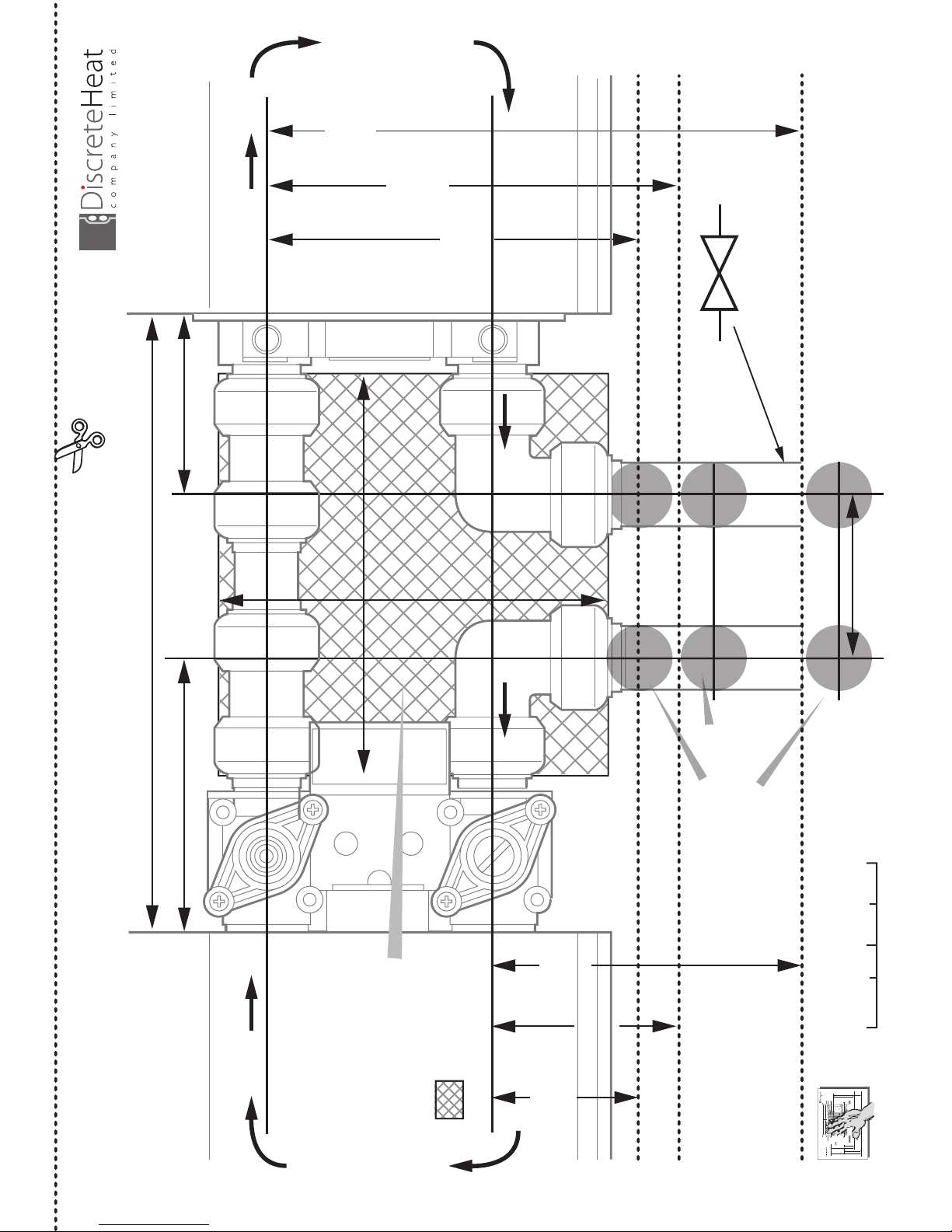
INSTALLATION
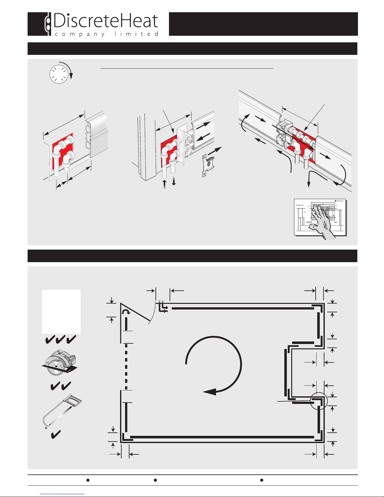
1. POSITION FEED PIPES (continued)
2. CUTTING SKIRTING TO LENGTH (when not supplied pre-cut)
Page 2
TM
120mm
TRV
FR
40mm
40mm
20mm
40mm
20mm
40mm
50mm
100mm
100mm
20mm
Archway,
patio, door
obstruction,
etc.
20mm
20mm
20mm
= (L1-160mm)
L1
L2
L3
L4
L5
L6
L7
L8
L9
= (L8-120mm)
= (L9-150mm)
(Threshold Kit)
CLOCKWISE
SYSTEM
SHOWN
= (L7-60mm)
= (L2-60mm)
= (L6-60mm)
= (L3-20mm)
= (L5-20mm)
= (L4-5mm)
24 TPI minimum
PIPE CONNECTORS NEED TO BE SET INTO THE WALL
FOR ALL TEMPLATES VISIT www.discreteheat.co.uk/technical.html
See pages 9-12 for pipe templates
130mm
65mm
120mm
90mm
60mm
95mm
100mm
45mm
65mm
130mm
DOUBLE TRV INSTALLATION TEMPLATE(Sheet 1 of 2)
Through floor pipework
(Left and right feed)
DO NOTSC ALE DRGWHEN PRINTING
75mm
0 20 40mm
CLOCKWISE SHOWN
150mm
BI-DIRECTIONAL TRV
Relieve plasterwork
150mm x 100mm to a depth of 5mm
12
6
9 3 SINGLE TRV
Relieve plasterwork
100mm x 100mm to a depth of 5mm
(See template p.9)
Feed
15mm
(16mm to order)
Return
15mm
(16mm to order)
120mm
Feed and Return pipes tight to wall
Relieve plaster for fittings.
65mm
35mm
120mm
See page 6

Tel: 0845 1238367 Fax: 01942 665104 e-mail: info@discreteheat.co.uk web: www.discreteheat.co.uk
INSTALLATION
2. CUTTING SKIRTING TO LENGTH (when not supplied pre-cut)
Page 3
TM
0~3mm (0.0") 50mm (2")
DEBURR!
Keep parallel
Deburring tool
(Part No. STOOL)
100mm (4")
‘Bell Mouth’
deburr
20mm (0.8")
120mm (5")
!
Remove all chaff
and debris
40mm 20mm
TRV Feed/return
1x clip at back 1x clip at back
2x clips at front 2x clips at front 1x clip at front1x clip at front, 1x clip behind
2x clips at front 1x clip at front (or back) 1x clip at front
COMMON CUTTING ALLOWANCES (note number and configuration of clips)
IMPORTANT - ALL CUT ENDS MUST BE DEBURRED AS SHOWN BELOW
IMPORTANT: All cut ends MUST be deburred to preserve your warranty.
Remove all chaff and debris to preserve your warranty. Problems may occur
if not properly removed.
Internal corner External corner Return manifold
Odd angle - internal Odd angle - external In-line joint (> 6m walls) Door architrave kit
Non TRV feed & return /
threshold kit
115mm (min)
Minimum active
length = 55mm (2.16")
Offer the flexible coupling up
centrally to the internal corner and
mark the wall at this point to give
the cut length of skirting
Push into corner
Avoid chafeing
on the corner
=
=
=
=
Offer flexible coupling up centrally
to the external corner and
mark the wall at this point to give
the cut length of skirting
Tel: 0845 1238367 Fax: 01942 665104 e-mail: info@discreteheat.co.uk web: www.discreteheat.co.uk
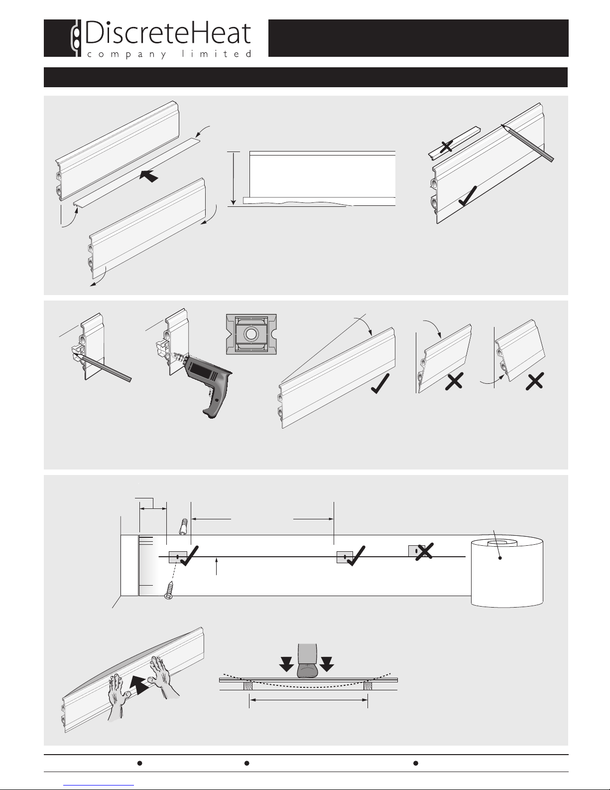
INSTALLATION
3.
MOUNTING BRACKETS - LT, TS & BM AND OG PROFILE ONLY
Page 4
TM
Make sure you allow for uneven/unlevel floors.
Bottom cover should be trimmed first.
?
Push in
90°
Click down
Mounting
bracket
USE THIS MARK TO POSITION MOUNTING
BRACKET USING AN OFF-CUT OF SKIRTING
THEN DRILL OR MARK WITH PENCIL
MARK TOP OF SKIRTING
WITHOUT CAULKING STRIP
OR
SHOULD YOU NEED TO MOVE THE SKIRTING,
PEEL AWAY FROM BRACKETS AS SHOWN.
DO NOT TILT UP OR DOWN!
100mm
from end of skirting
600mm - 700mm
Insulating foil, if required
(Part No. INSRL LT, INSRL TS or INSRL OG)
(older, solid walls without cavity)
±5mm
700mm approx.
7mm Ø
Gently push each piece back to the
wall and assess wall straightness, if
there any gaps greater than
10mm to the back edge of the
skirting, then apply moderate
pressure and see if the gap is
reduced, if it isn't, then it is
advisable to locally bend the skirting
as shown above.
LEAVE PROTECTIVE TAPE ON
DURING THE PROCESS!
LT,TS & OG ONLY

Tel: 0845 1238367 Fax: 01942 665104 e-mail: info@discreteheat.co.uk web: www.discreteheat.co.uk
INSTALLATION
3. MOUNTING - DECO PR
Page 5
TM
Feed
View on back
of TRV showing
fixings
DO NOT OVERTIGHTEN!
Return
!
12
6
9 3
CLOCKWISE
INSTALLATION
SHOWN
External
Corner
Internal
Corner
20mm
40mm
Check corners
not rubbing
GREASE
GREASE
GREASE
GREASE
ENSURE PIPES ARE VERTICAL AND
SQUARE TO THE SKIRTING!
START WITH TRV AT FEED AND RETURN PIPE END
‘O’ RINGS MUST BE GREASED!
‘O’ RINGS MUST BE GREASED!
GREASE SUPPLIED MUST BE USED ON ALL CONNECTORS TO AVOID DAMAGE ON ASSEMBLY
AND PRESERVE YOUR WARRANTY
‘O’ RINGS
MUST BE
GREASED!
CONTINUE ROUND THE ROOM REFERRING TO CORRECT
CLIP SEQUENCE ON PAGE 3.
4. INSTALLATION SEQUENCE
7mm Ø
60 - 1000mm
apart
ALL OTHER INFORMATION FOR SPACING, BENDING, ETC. IS AS OTHER PROFILES
WALL MOUNTED
FLOOR MOUNTED
Insulation foil (recommended)
- improves insulation and
prevents noise
Cut-away black plastic
guide to allow the other centre-
clip covers to fit in the slot

Tel: 0845 1238367 Fax: 01942 665104 e-mail: info@discreteheat.co.uk web: www.discreteheat.co.uk
INSTALLATION
4. INSTALLATION SEQUENCE (continued)
Page 6
TM
‘CLICK!’
PUSH
20mm
40mm
‘CLICK,
CLICK,
CLICK!’
!
!
ENSURE BOTH SIDES ARE LEVEL
WITH EACH OTHER
In this case only, reverse the connector
and clip to retain the final section
CHECK THAT THE FINAL PIECE CANNOT COME OFF UNDER PRESSURE
If a return manifold follows an internal corner, double clips must be used.
FITTING FINAL SECTION
5. CORNERS AND COVERS
!
ENSURE BOTH SIDES
ARE LEVEL WITH
EACH OTHER
See separate instructions provided
with Regency OG & Deco PR
1
2
Mitre top gaskets before
fitting corner cover
TOP TIP:
Soak top gasket in warm
soapy water for easy fitting
Add a touch of super glue onto mitre
before fitting the corner cover
5mm
Tel: 0845 1238367 Fax: 01942 665104 e-mail: info@discreteheat.co.uk web: www.discreteheat.co.uk
INSTALLATION
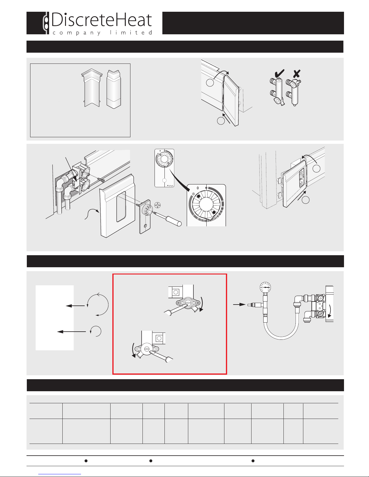
5. CORNERS AND COVERS (continued)
Page 7
TM
Position holes in
knob as shown to
access 2 fixing screws
for TRV controls
NEW SLIM INTERNAL
AND EXTERNAL
CORNERS ARE NOW
AVAILABLE FOR THE
URBAN LT
See separate instructions supplied
Peel off SuperVelcro
backing
Check back of cover
is clean and free
from grease
Pz x 2
Pz1
6. FINAL CHECKS
TRV Unit
Return Manifold
Clockwise Installation
Anti-clockwise Installation
OFF
AIR
1 ~ 2 bar
OFF A pressure test of the system before
connecting to the central heating
system is recommended.
(See part no.TTEST)
OFF
2
1
Material Output (per M @ dT50°C) Feed & Return Weight Capacity Corrosion Min. Flow Surface Complies Recommended
BTU / W Pipe Kg per m Litres per m Resistance Rate Finish with Max. OperatingTemp.
Unique Polymer & TS/LT > 500BTU / 150W 15mm 1.4kg LT 0.5 l/m Excellent 10 c.c. per sec Epoxy Powder BS-EN ≤75°C
Aluminium Alloy OG > 700BTU / 210W 16mm to order 1.7kg OG See Section 8 0.6 litre/min to BS-EN 12206-1 442
PR > 450BTU / 135W 1.2kg PR ‘Running your system’
7. TECHNICAL SPECIFICATION
ON
ON
OFF
Clip return manifold
cover top and bottom
Clip TRV Cover Top and Bottom
Note:TRV cover is completely secured by the
Valve facia
RETURN MANIFOLD COVER FIXING (LT & TS)
TRV COVER FIXING (LT & TS)
1
2
1
2
Use correct size
screwdriver
1/4” (6.5mm)
to avoid damage
Use correct size
screwdriver
1/4” (6.5mm)
to avoid damage

Tel: 0845 1238367 Fax: 01942 665104 e-mail: info@discreteheat.co.uk web: www.discreteheat.co.uk
INSTALLATION
8. RUNNING YOUR SYSTEM
Page 8
TM
Run the system at fully open, maximum temperature for 1 hour, to expel any air in the system. Release any air that may be trapped at appropriate
radiator bleed points and return manifold bleed point. Turn off TRV/flow manifold and allow to cool. Set to desired room setting and run
normally. NOTE: DiscreteHeat recommend flushing the system with ThermaSkirt Cleanser TS3 or alternatively Scalemaster SM3 (check dosage
carefully) and running with ThermaSkirt corrosion inhibitor TS5 or alternatively Scalemaster SM5 or SM10 (check dosage carefully) to
ensure maximum longevity and reliability. Hard water areas may require additional precautions. Chemically softened water must NOT be used. This is
a standard precaution for ALL wet heating systems and a requirement of BS 7593:2006. Contact DiscreteHeat for specific application advice.
Failure to provide a suitable corrosion inhibitor will invalidate your warranty!
PROBLEM CAUSE SOLUTION
Leak at joint. Faulty / incorrect installation. Drain and replace fitting or ‘O” ring from spares kit.
Leak on ThemeSkirt pipes. No inhibitor fitted. Drain down, cleanse with TS3 and install inhibitor TS5.
Corrosion chemical/cleaner left in system Drain down, replace piece, cleanse with TS3 and refill.
ThermaSkirt not hot. Check boiler. Is heating ’ON’ and pressure OK?
Lockshield valve closed. Open Lockshield valve ( ).
TRV valve closed / off. Open TRV valve ( ).
Air trapped in pipework. See 10 below.
Water from return manifold Manifold not closed fully. Turn to ‘OFF’ position.
Noise - ticks & clicks when heat on Connectors & fittings rubbing on wall. Relieve plasterwork at Feed & Return and/or corner fittings.
Sudden ‘bangs’ ThermaSkirt length(s) cut too long, Check lengths & refit if necessary.
expanding and jumping off the bracket.
Internal corners clipped both sides. Check & remove/unclip unecessary clip.
TRV Unit
Trapped air expelled through boiler
Auto vent recommended to ease bleeding
CLOSE
1. System with ThermaSkirt®& Conventional Radiators.
2. New Installation with ThermaSkirt®Only.
On installation, in a convenient place at the highest point
of the system, ‘T’ off into a vertical leg 600mm high and
install an automatic/manual air vent.
Following the procedure above, close and open each
ThermaSkirt®system in turn.
Any air forced round the system will be expelled through
the boiler or through the air vent.
Air can also be bled from the bleed screw on top of the
return manifold (A).
As ThermaSkirt®acts like a pipe, in normal operation air does not get trapped. However, on existing systems, to which ThermaSkirt is added, air
®
®
Trapped air expelled through boiler
600mm (min)
AV
A
9. TROUBLE SHOOTING
10.BLEEDING YOUR SYSTEM
may get trapped in the existing pipework to and from the skirting. Follow these simple steps if you discover cold sections of the ThermaSkirt
which do not heat up.
Turn off all radiators and ThermaSkirt thermostatic and lockshield
valves. Make sure your system is fully pressurised and the pump is
set to max. Run the system for a few minutes, and, starting from
the lowest point in the house, open each
radiator/ThermaSkirt system, one at a time. Run for a further 2
minutes (approx) , close again and move to the next Ther-
maSkirt or radiator, moving upwards in the house. Any air will
be expelled through the boiler or trapped in a conventional
radiator. Bleed the radiator as normal.
CLOSE
100mm
120mm
Plan view for drilling feed and return
pipe holes in floor
Drill 2 x 18mm holes
touching wall surface
Drill 2 x 18mm holes
touching wall surface
65mm
65mm 35mm
20mm
75mm
95mm
35mm
Relieve plaster/
surface finish to a
depth of 5mm in this
hatched area to allow
for Tectite fittings
FEED
(TRV VALVE)
RETURN
(LOCKSHIELD
VALVE)
35mm
Fold along here for Urban LT / Classic TS template
Fold along here for Deco PR template
Fold along here for Regency OG template
Cut along dotted line
)evartihcrayawroodrollawfodnenoecalP(erehgnoladlof/tuC
LH END
100mm
(LT)
45mm
(LT)
35mm
(PR)
130mm
(OG)
90mm
(PR)
SINGLE TRV INSTALLATION TEMPLATE)
(Through floor pipework)
DO NOT SCALE DWG WHEN PRINTING
75mm
(OG)
WALL
FINISHED FLOOR LEVEL
WALL
FINISHED FLOOR LEVEL
WALL
FINISHED FLOOR LEVEL
0 20 40
mm
Drill2 x 18mm holes
(Seesheet 2 for location)
130mm
65mm
120mm
90mm
60mm
95mm
100mm
45mm
Relieveplaster/
surfacefinish to a
depthof 5mm in
thisshaded area
toallow for
Tectitefittings
Relieveplaster/surface finish
toa depth of 25mm in this dark
shadedarea to allow feed
pipeto go behind Tectite
fitting
65mm
130mm
DOUBLETRV INSTALLATIONTEMPLATE (Sheet 1 of 2)
Throughfloor pipework
(Leftand right feed)
DONOT SCALE DRG WHEN PRINTING
75mm
Cut/foldalong here for Urban LT template
Cut/foldalong here for Regency OG template
WALL
FLOOR
WALL
FLOOR
FEED
(TRVVALVE)
FEED
(TRVVALVE)
RETURN
(LOCKSHIELD
VALVE)
RETURN
(LOCKSHIELD
VALVE)
0 20 40
mm
STICK TO WALL
TO USE
LH END clockwise installation
RH END anti-clockwise installation
Tel: 0845 1238367 Fax: 01942 892836
web: www.discreteheat.co.uk
)evartihcrayawroodrollawfodnenoecalP(erehgnoladlof/tuC
12
6
9 3
12
6
9 3

80mm
80mm
100mm
100mm
Plan view for drilling feed and return
pipe holes in floor
Drill 2 x 18mm holes
touching wall surface
Drill 2 x 18mm holes
touching wall surface
50mm 50mm
80mm 80mm
100mm 100mm
32mm 32mm
)yawroodrollawfodnenoecalP(erehgnoladlof/tuC
)yawroodrollawfodnenoecalP(erehgnoladlof/tuC
Fold along here for
Regency OG template
NON TRV / THRESHOLD KIT PIPE INSTALLATION TEMPLATE
(Through floor pipework)
DO NOT SCALE DWG WHEN PRINTING
0 20 40
mm
Relieve plaster/surface finish to a
depth of 5mm in this hatched
area to allow for Tectite fittings
Fold along here for
Urban LT /
Classic TS template
Fold along here for
Deco PR template
LH END RH END
WALL
WALL
FINISHED FLOOR LEVEL
FINISHED FLOOR LEVEL
WALL
FINISHED FLOOR LEVEL
130mm
(OG)
75mm
(OG)
100mm
(LT)
90mm
(PR)
45mm
(LT)
35mm
(PR)
Drill2 x 18mm holes
(Seesheet 2 for location)
130mm
65mm
120mm
90mm
60mm
95mm
100mm
45mm
Relieveplaster/
surfacefinish to a
depthof 5mm in
thisshaded area
toallow for
Tectitefittings
Relieveplaster/surface finish
toa depth of 25mm in this dark
shadedarea to allow feed
pipeto go behind Tectite
fitting
65mm
130mm
DOUBLETRV INSTALLATIONTEMPLATE (Sheet 1 of 2)
Throughfloor pipework
(Leftand right feed)
DONOT SCALE DRG WHEN PRINTING
75mm
Cut/foldalong here for Urban LT template
Cut/foldalong here for Regency OG template
WALL
FLOOR
WALL
FLOOR
FEED
(TRVVALVE)
FEED
(TRVVALVE)
RETURN
(LOCKSHIELD
VALVE)
RETURN
(LOCKSHIELD
VALVE)
0 20 40
mm
STICK TO WALL
TO USE
LH and RH installation
Tel: 0845 1238367 Fax: 01942 892836
web: www.discreteheat.co.uk
150mm
Plan view for drilling
feed and return pipe
holes in floor
Drill 2 x 18mm holes
touching wall surface Fit separate isolation valve
65mm 45mm
95mm
Feed
Relieve plaster/
surface finish to a
depth of 5mm in this
hatched area to allow
for Tectite fittings
40mm
100mm
(LT)
45mm
(LT)
35mm
(PR)
130mm
(OG)
BI-DIRECTIONAL TRV INSTALLATION TEMPLATE (LH feed direction)
(Through floor pipework)
DO NOT SCALE DRG WHEN PRINTING
75mm
(OG)
WALL
FINISHED FLOOR LEVEL
WALL
FINISHED FLOOR LEVEL
WALL
FINISHED FLOOR LEVEL
020 40
mm
Drill2 x 18mm holes
(Seesheet 2 for location)
130mm
65mm
120mm
90mm
60mm
95mm
100mm
45mm
Relieveplaster/
rfacefinish to a
pthof 5mm in
isshaded area
toallow for
Tectitefittings
Relieveplaster/surface finish
toa depth of 25mm in this dark
shadedarea to allow feed
pipeto go behind Tectite
fitting
65mm
130mm
DOUBLETRV INSTALLATIONTEMPLATE (Sheet 1 of 2)
Throughfloor pipework
(Leftand right feed)
DONOT SCALE DRG WHEN PRINTING
75mm
Cut/foldalong here for Urban LT template
Cut/foldalong here for Regency OG template
WALL
FLOOR
WALL
FLOOR
FEED
(TRVVALVE)
FEED
(TRVVALVE)
RETURN
(LOCKSHIELD
VALVE)
RETURN
(LOCKSHIELD
VALVE)
02040
mm
STICK TO WALL
TO USE
Tel: 0845 1238367 Fax: 01942 892836
e-mail: [email protected].uk
web: www.discreteheat.co.uk
Fold along here for
Urban LT
Fold along here for
Deco PR
90mm
(PR)
100mm
Return
Cut along dotted line

150mm
Plan view for drilling
feed and return pipe
holes in floor
Drill 2 x 18mm holes
touching wall surface
65mm45mm
95mm
Feed
Relieve plaster/
surface finish to a
depth of 5mm in this
hatched area to allow
for Tectite fittings
40mm
100mm
(LT)
45mm
(LT)
35mm
(PR)
130mm
(OG)
BI-DIRECTIONAL TRV INSTALLATION TEMPLATE (RH feed direction)
(Through floor pipework)
DO NOT SCALE DRG WHEN PRINTING
WALL
FINISHED FLOOR LEVEL
WALL
FINISHED FLOOR LEVEL
WALL
FINISHED FLOOR LEVEL
020 40
mm
Drill2 x 18mm holes
(Seesheet 2 for location)
130mm
65mm
120mm
90mm
60mm
95mm
100mm
45mm
Relieveplaster/
rfacefinish to a
pthof 5mm in
isshaded area
toallow for
Tectitefittings
Relieveplaster/surface finish
toa depth of 25mm in this dark
shadedarea to allow feed
pipeto go behind Tectite
fitting
65mm
130mm
DOUBLETRV INSTALLATIONTEMPLATE (Sheet 1 of 2)
Throughfloor pipework
(Leftand right feed)
DONOT SCALE DRG WHEN PRINTING
75mm
Cut/foldalong here for Urban LT template
Cut/foldalong here for Regency OG template
WALL
FLOOR
WALL
FLOOR
FEED
(TRVVALVE)
FEED
(TRVVALVE)
RETURN
(LOCKSHIELD
VALVE)
RETURN
(LOCKSHIELD
VALVE)
02040
mm
STICK TO WALL
TO USE
Tel: 0845 1238367 Fax: 01942 892836
e-mail: [email protected].uk
web: www.discreteheat.co.uk
Fold along here for
Urban LT
Fold along here for
Deco PR
90mm
(PR)
100mm
Return
75mm
(OG)
Fit separate isolation valve
Table of contents
Other DiscreteHeat Heater manuals


