displayit 8' flare User manual

8’ (92” x 185”) Flare
Assembly Instructions Page 1
Flare v2.0 Updated 1/23/2018
displayit.com 800.207.0311 After-Hours Emergency: Call or Text 678.723.5343
6 - Frame Perimeter Pieces
(See Diagram 1 for details)
4 - Flat Connecting Plates with Wing Nuts
4 - Corner Connecting Plates with Wing Nuts
4 - Extra Wing Nuts
(1/4-20 Thread Size)
1 - Horizontal Support Bar
8 - Double-Sided Curtain Lights
8 - Power Supplies (100 Watts)
32 - Light Mount Clips*
2 - 10 Foot Power Cords with 5 Quick-Connects
6 - Wire Management Clips
2 - Flare Base Feet
8 - Screws for Flare Feet
(1/4-20 Thread Size)
8 - Washer Wing Nuts for Flare Feet*
(1/4-20 Thread Size)
1 - Displayit Multi-Tool
Need Help?
Scan the QR code or go to
displayit.com/flare-guide
to watch an assembly video.

8’ (92” x 185”) Flare
Assembly Instructions Page 2
Flare v2.0 Updated 1/23/2018
displayit.com 800.207.0311 After-Hours Emergency: Call or Text 678.723.5343
Power Supply Velcro
Power Supply Velcro
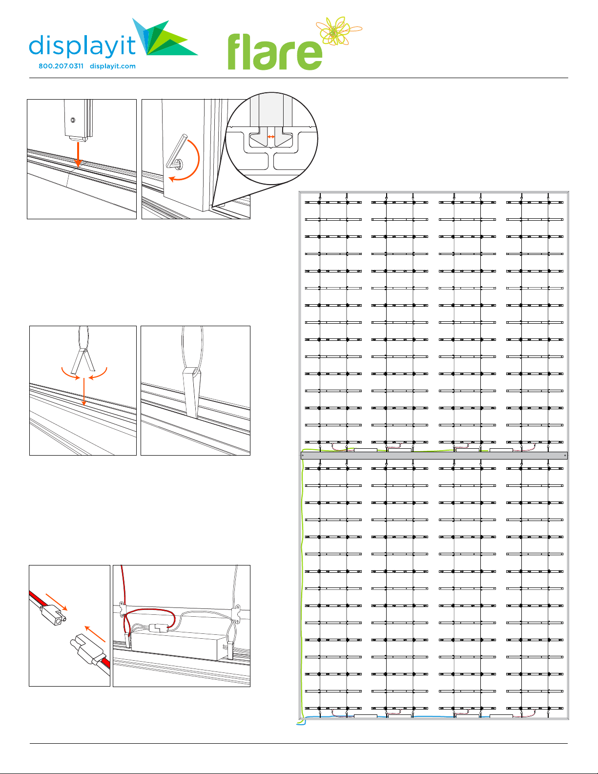
1. Upack the frame. Save all foam pieces for repacking later. Lay out the frame pieces as seen in Diagram 1.
Frame perimeter pieces are labeled with stickers matching Diagram 1 to make this step easier.
Take note where the velcro strips for the power supplies are located on Diagram 1.
Assemble the frame on its back.
Diagram 1
92” BOTTOM
DBL. CORNERS
92” SIDE
CORNER
92” SIDE
CORNER
92” SIDE
CORNER
92” SIDE
CORNER
92” TOP
DOUBLE
CORNERS
Horizontal Support Bar
2. Assemble frame sides using
two flat connecting plates.
Hand tighten wing nuts to
secure.
3. Assemble perimeter of
frame with four corner
connecting plates.
Note: It’s best to build the frame laying on its back.
CAUTION:
METAL EDGES
MAY BE SHARP
8’ (92” x 185”) Flare
Assembly Instructions Page 3
Flare v2.0 Updated 1/23/2018
displayit.com 800.207.0311 After-Hours Emergency: Call or Text 678.723.5343
4. Locate the break where the two 92” Side Corner frame
pieces meet. Insert the Horizontal Support Bar in the
center channel at this point.
5. Using the provided multi-tool, rotate the 5mm hex key
clockwise to lock Horizontal Support Bar in place. Repeat
on opposite side.
6. Attach the bottom of the curtain to the center
channel of the frame using light clips (Diagram 2).
To attach clips, hook each clip through the wire loop.
Squeeze clip, insert into channel, and release.
Suggested light clip locations are marked on the ruler.
Carefully unroll the curtain light and clip the top clips
into the top of the frame, keeping the wires straight.
Diagram 2
7. Attach the power supplies to the frame via the velcro
strips and connect the wires to the curtain lights.
8’ (92” x 185”) Flare
Assembly Instructions Page 4
Flare v2.0 Updated 1/23/2018
displayit.com 800.207.0311 After-Hours Emergency: Call or Text 678.723.5343
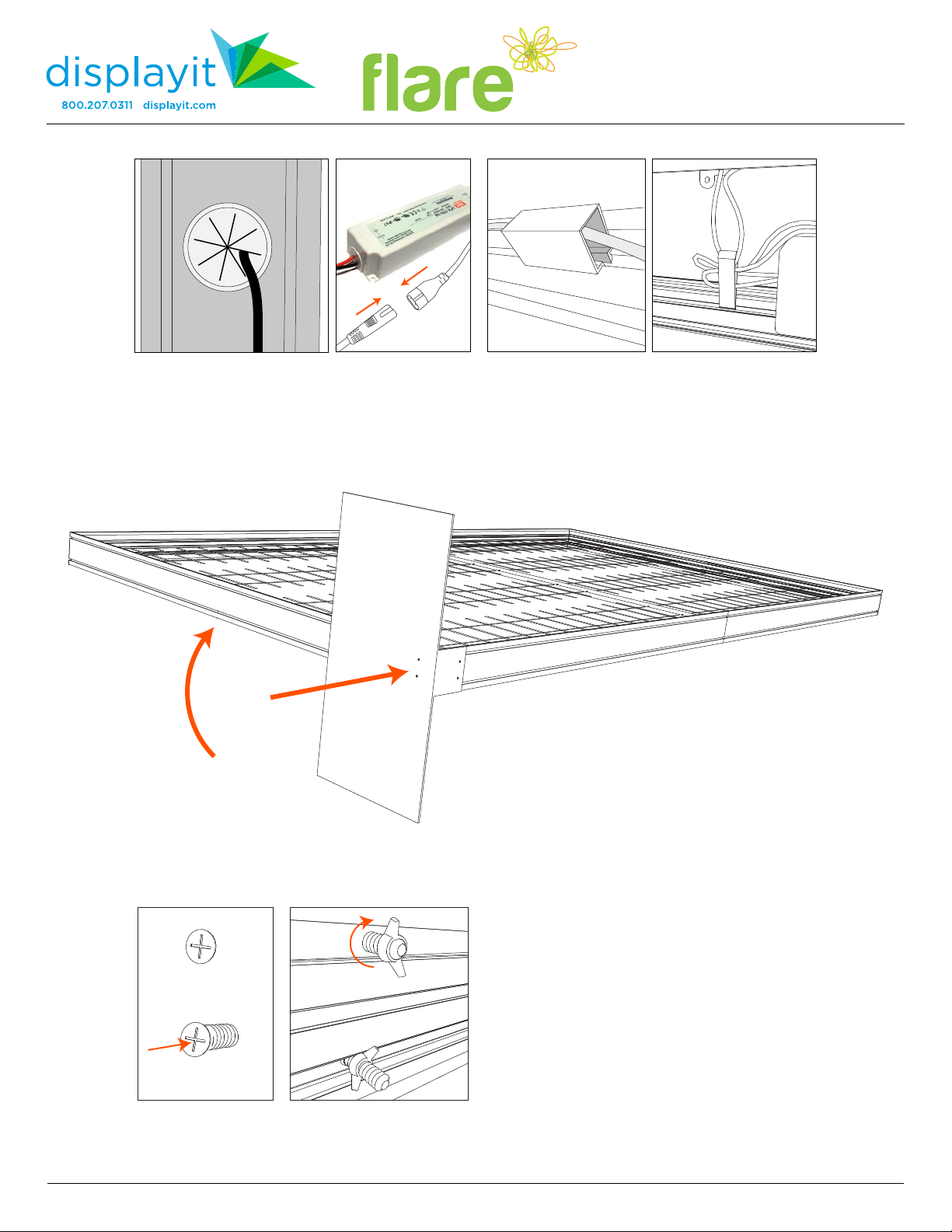
Diagram 3
9. To help stop wire shadows on the graphic, use
the provided snap-on wire management clips.
The curtain light clips may also be used for wire
management.
8a. Run two power cables as shown by the blue
and green lines in Diagram 2.
8b. Run the main power cables through the wire
pass-through and connect to the power supply.
Plug the cables into an AC outlet to test the lights.
11. Slide in two side screws and hand-tighten
with wing nuts.
Repeat steps 10-11 for second Base Foot.
10. Prop up the bottom of frame as shown in
Diagram 3. Place the Base Foot against the corner
of the bottom right of frame. Slide in two bottom
screws and hand-tighten with wing nuts.

8’ (92” x 185”) Flare
Assembly Instructions Page 5
Flare v2.0 Updated 1/23/2018
displayit.com 800.207.0311 After-Hours Emergency: Call or Text 678.723.5343
1. Using at least two people,
carefully stand the display up.
Starting in top-left corner, turn
and tuck graphic and silicone
into the channel. (#1 on diagram)
Use your fingertip (not fingernail)
for installation.
Note: For large frames, a step ladder
may be required for graphic installation.
2. Work across the top, tacking the graphic into the channel
every two to three feet. (#2 on diagram)
3. Tuck top, right corner into channel. (#3 on diagram)
4. Tuck remainder of top edge of graphic into top channel.
(#4 on diagram)
5. Inspect graphic for hard fold lines in the fabric.
If desired, smooth them out using a fabric steamer.
6. Tuck bottom two corners. (#6 on diagram)
7. Tack middle of sides. (#7 on diagram)
8. Working from top to bottom, tuck remaining silicone in
on both sides. (#8 on diagram)
9. Tack middle of bottom. (#9 on diagram)
10. Tuck remaining bottom edge, working from outside to
inside. (#10 on diagram)
11. Repeat installation steps for fabric on back of frame.
1 2 2 2 3
6 6
77
44
91010
88
Fabric
Graphic
Silicone Welt
(On Back)
Graphic Installation
Silicone
Silicone
Fabric
Fabric
Top of Frame
Caution! Installing silicone-edged graphics is techniqe sensitive;
Practice will shorten installation time.
Handle graphics with care with clean hands in a clean environment.
Cloth or latex gloves recommended.
Keep graphics away from sharp objects.
8’ (92” x 185”) Flare
Assembly Instructions Page 6
Flare v2.0 Updated 1/23/2018
displayit.com 800.207.0311 After-Hours Emergency: Call or Text 678.723.5343
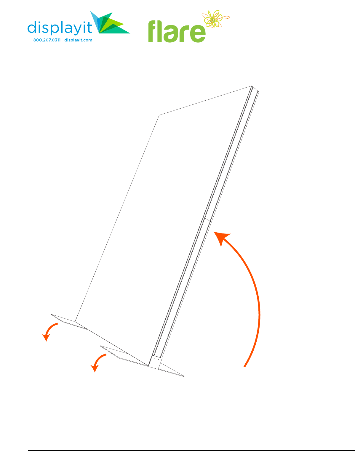
12. Carefully stand the frame up, using the
feet as a pivot.
This should only be done by
four or more people.
Table of contents
Popular Industrial Monitor manuals by other brands

Matrix Orbital
Matrix Orbital MOP-TFT480272-43A-BLM-CTB Hardware manual

Canvys
Canvys DCT08D00893BE user manual

Pentair
Pentair Raychem ECW-GF-DP Installation and operating instructions

Eaton
Eaton XV-152 Series operating instructions

Advantech
Advantech FPM-5171G Series user manual

Unitronics
Unitronics UniStream USP-070-B08 installation guide


