C.ITOH CIT224 User manual
CIT224
Video Display Terminal
1
1
User's
Manual
ell
H

USER'S MANUAL
CIT224
VIDEO TERMINAL
C.ITOH
CIE Terminals
© 1987
P.N. 093-056
REV. 224-UM-02
January 1987

Al I
rights
reserved.
No
part
of
this
book
may
be
reproduced
in
any
form
by
any
electronic
or
mechanical
means.
NOTICE
This
equipment
generates,
uses,
and
may
emit
radio
frequency
energy
and
if
not
installed
and
used
in
accordance
with
the
instructions
manual,
may
cause
interference
to
radio
communications.
The
equipment
has
been
tested
and
found
to
comply
with
the
limits
for
a
Class
A
computing
device
pursuant
to
Subpart
J
of
Part
15
of
FCC
rules,
which
are
designed
to
provide
reasonable
protection
against
such
interference
when
operated
in
a
commercial
environment.
Operation
of
this
equipment
in
a
residential
area
may
cause
interference
in
which
case
the
user,
at
his
own
expense,
may
be
required
to
take
measures
to
correct
this
interference.
This
document
reflects
the
features
and
specifications
of
the
CIT224.
CIE
Terminals
reserves
the
right
to
make
changes
and
improvements
in
features
and
specifications
at
any
time
without
prior
notice
or
obligation.
The
following
are
trademarks
or
equipment
designations
of
CIE
Terminals:
CIT224
CIT-220+
CIT-101e
CIT-101
The
following
are
trademarks
or
equipment
designations
of
the
Digital
Equipment
Corporation,
Maynard,
Massachusetts.
DEC
VT52
VT100
VT101
VT102
VT200
VT220
TABLE
OF
CONTENTS
CHAPTER 1 INTRODUCTION
Product
Description
Features
........
.
Related
Documents
Specifications
CHAPTER 2 INSTALLATION
for
Damage
Unpacking
Inspection
Location
Electrical
Connections
Keyboard
Cable
Attachment
AC
Line
Voltage
Connection
Terminal
Checkout
Terminal
Operating
Interfacing
Configuration
Modems
••..•
21lJ
mA
Current
Loop
Communications
Port
Protocol
Unrecognized
XON/XOFF
Characters
Modem
Connect/Disconnect
Printer
Port
Protocol
Self-Test
.......
.
Initial
Power-on
Error
Messages
Care
and
Maintenance
CHAPTER 3
KEYBOARDS
Keyboard
Description
Main
Keypad
Keys
Standard
Keys
Main
Editing
Keyboard
Function
Keys
Keypad
Numeric
Keypad
., .
Keypad
Numeric
Mode
Keypad
Application
Mode
Bidirectional
Auxiliary
Terminal
Port
Keyboard
Keys
Control
and
Function
LED
Indicators
Audible
Indicators
Codes
Lock
Keyboard
Auto
Repeat
Keyboard
Generated
Control
Conditions
that
Cause
Keyboard
Keyboard
Layouts
Control
CIE
TERMINALS
Page
1-1
1-2
1-2
1-3
2-1
2-2
2-2
2-2
2-2
2-3
2-5
2-6
2-6
2-8
2-8
2-12
2-12
2-13
2-13
2-13
2-14
2-15
3-1
3-2
3-2
3-3
3-4
3-6
3-7
3-7
3-8
3-9
3-11
3-12
3-12
3-12
3-14
3-14
CIE
TERMINALS TABLE
OF
CONTENTS
CHAPTER 4 OPERATION
Operating
States
Set-Up
On-Line
Local
Modes
of
Operation
•....
VT200,
7-Bit
Mode
VT200,
8-Bit
Mode
VT100
Mode
VT52 Mode
Set-Up
Modes
Se-t-Up
Menus
Menu
Title
.
-.
Terminal
Identifier
Status
Line
........
.
Set-Up
Field
Parameters
Set-Up
Field
Cursor
.....
Selection
of
Set-Up
SAVE
and
RECALL
Screen
Operations
Menus
Set-Up
Mode
Menus
Set-Up
Directory
Menu
Display
Display
General
General
Set-Up
Menu
Enhancements
Menu
Set-Up
Menu
......•
Enhancements
Set-Up
Communications
Printer
Se"t-Up
Set-Up
Menu
Menu
Aux
Port
Enhancements
Keyboard
Set-Up
Menu
Keyboard
Enhancements
Tab
Set-Up
Menu
.....
.
Set-Up
Set-Up
Menu
Menu
Menu
Function
Key
Editor
Page
Operation
of
Function
Display
Controls
Key
Editor
Print
Modes
Print
Mode
Mode
Normal
Auto
Print
Printer
Controller
Mode
Concurrent
Print
Local
Controller
Compose
Character
Mode
Mode
Sequences
Sequence
Three-Key
Compose
Two-Key
Compose
Sequence
Page
To
Abort
or
Restart
a
Compose
Sequence
Page
4-1
4-1
4-1
4-1
4-2
4-2
4-2
4-2
4-2
4-3
4-3
4-3
4-4
4-4
4-5
4-6
4-7
4-7
4-7
4-8
4-10
4-11
4-13
4-15
4-16
4-18
4-20
4-21
4-23
4-24
4-25
4-26
4-27
4-30
4-30
4-30
4-30
4-31
4-31
4-31
4-31
4-32
4-36
CIE
TERMINALS
TABLE
OF
CONTENTS
CHAPTER
5 -
PROGRAMMER
DATA
Programming
Features
......................................
.
Terminology
..............................................
.
Entering
Commands
........................................
.
Command
Structure
......................................
.
Operating
States
..........................................
.
Modes
of
Operation
.•.......••...•.•.•..•............••...••
Character
Encod
i
ng
•••.••....••..•..••..••.•....•.....•..•..
7-
and
8-Bit
Character
Operation
••...••••..••..•••••••..•.•
Control
Codes
............................................
.
Control
Zero
(eli})
•••••••••••••••••••••••••••••••••••••••
Control
One
(C1)
7-Bit
Code
Extension
Technique
.••.•..••.••.•••...•.•..•
Contro
1
Sequences
........................................
.
Escape
Sequence
..•...........•.....•....................
Con
t r
01
Sequence
......................................
.
Device
Control
Strings
...•...••..•..•....•.•...........
Graphic
Characters
........................................
.
,
Graphic
Left
...........................................
Graph
i c
Ri
ght
..••..••..•....•.....•.....•..........•..••
Character
Set
Reper
to
ire
...........•••..•...••.....•..•
ASC
II
Graphics
.........•.••..••.•...••••...•........
Supp
I
ementa
I
Graphi
cs
...•..••..•....••..••..••...•...
Special
Graphic.s
...................................
.
National
Replacement
Character
(NRC)
Sets
.••.........
Soft
Character
Set
................................
".
Load
i
ng
Character
Sets
.••..••...•...•...•........•.•.••
Designate
Character
Sets
......•.•..••...•.....•••..•
1
nvok
i
ng
a
Character
Se
t
.•......................•...
"Sof
t"
Character
Sets
••.......•.....•....•.....•.•......
Defining
a
Character
Set
using
the
CIET
Method
.....•
Defining
Special
Graphics
..........................
..
Down-Line
Loading
Each
Character
using
the
CIET
Method
•..........•.................
Defining
a
Character
Set
using
the
DEC
Compatible
Method
d
......................
.
Down-Line
Loading
Each
Character
using
the
DEC
Compatible
Method
....••....•........
C I ea'\-
Character
Set
...........••..•..................
Page
5-1
5-1
5-2
5-2
5-2
5-3
5-4
5-4
5-4
5-5
5-7
5-9
5-10
5-10
5-10
5-10
5-11
5-11
5-11
5-12
5-12
5-12
5-12
5-12
5-13
5-13
5-14
5-16
5-17
5-18
5-19
5-20
5-21
5-25
5-26
Control
Sequence
Functions
..••.•...•..•........•...........
5-27
Set
Opera
t i
ng
Modes
•••••.••....•••..••..•...........•...
5-27
Set
VT200
7-8
it
Mode
......•..••.
. • . . • . • • . . . . . . . . . .
..
5-27
Set
VT200
8-Bi
t
Mode
•...•..•••....•...•........••..•
5-27
Set
VT100
Mode
...•......•..............•..••..•...••
5-28
Set
VT52
Mode
•.....•.......•.....•......•......•.....
5-28
Set
C1
Control
Code
Transmission
5-28
CIE
TERMINALS TABLE
OF
CONTENTS
CHAPTER 5
PROGRAMMER
DATA
(Continued)
Terminal
Modes
Auto
Repeat
Mode
Auto
Wrap
Mode
Character
Insert/Replace
Character
Set
Mode
Column
Mode
Mode
Cursor
Key
Application
Cursor
Origin
Mode
Keyboard
Action
Mode
Keypad
Application
Line
Feed-New
Line
Print
Extent
Mode
Mode
Mode
Mode
Print
Form
Screen
Mode
Feed
Mode
Scrolling
Mode
Send-Receive
Mode
Text
Cursor
Enable
Mode
Cursor
Control
Sequences
Relative
Cursor
Positioning
Cursor
Positioning
Direction
..•.•
Direct
Scro
I I
Next
Line
.......
.
Save
and
Restore
Cursor
and
Attributes
Tabulation
Set
Horizontal
Tab
Commands
Rendition
Clear
Tab(s)
Width/Height
Line
Select
Graphic
Editing
Commands
Insert/Delete
Insert/Delete
Line
Character
Erase
Control
Sequences
Set
Erase
Character
Character(s)
Erase
Selective
Erase
Attribute
Erase
Screen/Line:
Attributes
Erase
within
Screen
Erase
within
Line
Screen/Line:
Attributes
Erase
Erase
within
Erase
within
Scrolling
Region
Screen
Line
Protected
Unprotected
Page
5-28
5-29
5-29
5-30
5-30
5-30
5-30
5-30
5-31
5-31
5-31
5-32
5-32
5-32
5-32
5-32
5-33
5-33
5-33
5-33
5-33
5-34
5-34
5-34
5-34
5-34
5-34
5-35
5-36
5-36
5-36
5-37
5-37
5-37
5-37
5-38
5-38
5-38
5-38
5-38
5-38
5-39

TABLE OF CONTENTS
CHAPTER 5
PROGRAMMER
DATA
(Continued)
Print
Commands
Print
Cursor
Print
Screen
Line
Auto
Print
Mode
Controller
Printer
CIET
Mode
Commands
Private
Printer
Status
Line
25th
Row
User-Defined
Reports
Keys
(UDK'S)
Resetting
the
Terminal
Hard
Terminal
Reset
Soft
Terminal
Reset
Self-Test
Diagnostics
Error
Messages
Screen
Alignment
VT52 Mode
Escape
Sequences
Cursor
Control
Sequences
Erase
Control
Sequences
Graphics
Mode
..........
.
Keypad
Application
Mode
Bidirectional
Auxiliary
Port
Scro
I I
ANSI Mode
Request
Identity
APPENDIX A
Code
Tables
APPENDIX B
Control
Codes
APPENDIX C
Control
Sequences
APPENDIX D
Set-Up
Screens
Control
..
CIE
TERMINALS
Page
5-39
5-39
5-39
5-39
5-40
5-40
5-41
5-42
5-46
5-49
5-49
5-50
5-51
5-51
5-53
5-54
5-54
5-54
5-54
5-55
5-55
5-55
5-55
5-55
A-1
8-1
C-1
D-1
CIE
TERMINALS
FIGURE
1-1.
2-1.
2-2.
2-3.
2-4.
2-5.
2-6.
2-7.
2-8.
3-1.
3-2.
3-3.
3-4.
3-5.
3-6.
3-7.
3-8.
3-9.
3-1m.
3-11.
3-12.
3-13.
3-14.
3-15.
3-16.
3-17.
3-18.
3-19.
3-2m.
4-1.
4-2.
4-3.
4-4.
4-5.
4-6.
4-7.
4-8.
4-9.
4-1m.
4-11.
4-12.
4-13.
5-1-
5-2.
TABLE
OF
CONTENTS
ILLUSTRATIONS
Video
Terminal
...••
Unpacking
.....
Mloni
tor
Contro
Is
CIT224
CIT224
CIT224
CIT224
CIT224
Male
D
Controls
and
Connectors
.....
.
Indicator
and
Power
Switch
Connector
Pin
Locations
<labeled
COMM)
Female
D
Connector
Pin
Locations
<labeled
AUX)
Active
Configuration,
2m
mA
Current
Loop
Passive
Configuration,
2m
mA
Current
Loop
CIT224
Keyboard
Main
Keyboard
Keys
Editing
Keypad
Numeric
Keypad
Terminal
Control
and
Function
Keys
North
American
Keyboard
British
Keyboard
Flemish
Keyboard
Canadian
(French)
Keyboard
•.•.•••.
Danish
Keyboard
Finnish
Keyboard
German
Keyboard
Dutch
Keyboard
Italian
Keyboard
Swiss
(French)
Keyboard
(German)
Keyboard
Keyboard
Norwegian
Keyboard
Swiss
Swedish
French
(Belgian)
Keyboard
Spanish
Keyboard
Set-up
Status
Line
Set-Up
Directory
Menu
Display
Set-Up
Menu
Display
Enhancements
Menu
General
Set-Up
Menu
......
.
General
Enhancements
Set-Up
Menu
Set-Up
Menu
Communications
Printer
Set-Up
Menu
.•.••.••.
Aux
Port
Enhancements
Set-Up
Menu
Keyboard
Set-Up
Menu
.••..•.......
Keyboard
Enhancements
Set-Up
Menu
Tab
Set-Up
Menu
••.......
Function
Key
Editor
Reloading
Character
"Soft"
Character
on
Page
Sets
7 x
16
Matrix
Page
1-1
2-1
2-3
2-4
2-5
2-7
2-8
2-1m
2-11
3-1
3-2
3-5
3-6
3-9
3-15
3-16
3-17
3-18
3-19
3-2m
3-21
3-22
3-23
3-24
3-25
3-26
3-27
3-28
3-29
4-4
4-8
4-1m
4-11
4-13
4-15
4-16
4-18
4-2m
4-21
4-23
4-24
4-25
5-14
5-18
CIE
TERMINALS
TABLE
OF
CONTENTS
ILLUSTRATIONS
(Continued)
FIGURE
Page
5-3.
CIET
Conversion
Process
..•.............•.•....•.•.•.•
5-19
5-4.
"Soft"
Character
on
7 x
10
Matrix
....•..........•..•.
5-22
5-5.
Example
of
a
Divided
Matrix
..........................
5-22
5-6.
DEC
Compatible
Conversion
Process
........•...........
5-24
TABLE
2-1.
2-2.
2-3.
2-4.
2-5.
2-6.
3-1.
3-2.
3-3.
3-4.
3-5.
3-6.
3-7.
4-1.
4-2.
4-3.
5-1.
5-2.
5-3.
5-4.
5-5.
5-6.
TABLES
Page
Communication
D
Connector
Pin
Assignments
......•.....
2-7
AUX
Port
D
Connector
Pin
Assignments
.•..............•
2-8
COMM
Port
D
Current
Loop
Pin
Assignments
......•...•..
2-9
AUX
Port
D
Current
Loop
Pin
Assignments
...•.......•..
2-9
Screen
Error
Messages
.......................•........
2-14
LED
Er
ror
Messages
..•..........•.....•...•.•••
10>
• • • •
••
2-15
Main
Keyboard
Function
Keys
.......•..................
3-3
Codes
Generated
by
Cursor
Control
Keys
....••.........
3-5
Codes
Genera
ted
by
Ed i t i
ng
Keys
......................
3-6
Numeric
Keypad
Generated
Codes
.......................
3-7
Numeric
Keypad
Special
Functions
.....................
3-8
Codes
Generated
by
Terminal
Control
&
Function
Keys
..
3-10
Keyboard
Generated
Control
Codes
........••...........
3-13
Display
Controls
Font
..•.•..........•....•...........
4-28
Multinational
Mode
Compose
Sequences
.••..............
4-33
National
Mode
Compose
Sequences
...•.........•........
4-37
Contro
1
Codes
........................................
5-5
Supported
C0
Control
Codes
......•....................
5-6
Supported
C1
Control
Codes
...............•...........
5-8
Designating
Character
Sets
...........................
5-15
I
nvoking
Character
Sets
..••...................•......
5-17
Sof
t
Reset
States
••••...•............................
5-50


CIE
TERMINALS
Chapter
1
INTRODUCTION
PRODUCT
DESCRIPTION
The
CIT224
is
a
versatile,
low
cost,
multifunctional
video
data
terminal
with
a
lS8-key
detachable
keyboard.
The
terminal
allows
the
user
to
communicate
with
a
host
computer
system
via
the
keyboard
and
display
screen.
The
CIT224
can
be
interfaced
with
a
variety
of
computer
system~
and
peripheral
devices.
It
is
compatible
with
the
following
terminals:
DEC
VT22S,
VT1SS
and
VT52,
and
CIE
Terminals
CIT-1Sle,
CIT-1Sl
and
CIT-22S+.
Figure
1-1.
CIT224
Video
Terminal
Introduction
1-1
CIE
TERMINALS
The
CIT224
operates
in
either
an
ANSI
mode
or
a
VT52
mode.
In
the
ANSI
mode
the
terminal
uses
American
National
Standards
Institute
(ANSI)
programming
standards
and
is
compatible
with
DEC
VT220
and
VT100,
and
CIE
Terminals
CIT-101e,
CIT-101
and
CIT-220+
video
termin-
als.
In
the
VT52
mode,
the
CIT224
is
compatible
with
DEC
VT52
terminals.
FEATURES
Standard
features
include
a
ful
I
and
half
duplex
communication
mode,
RS-232-C
or
20
mA
current
loop
communication
interface,
and
an
auxiliary
full
duplex
port.
The
CRT
has
a
14-inch
diagonal
screen
with
a
choice
of
a
black
and
white,
green,
or
amber
phosphor.
Additional
features
of
the
CIT224
include:
Keyboard
layouts
available
in
15
languages
A
total
of
60
function
keys,
15
fixed,
45
programmable
in
non-
volatile
memory
in
either
VT100
or
VT220
mode
A
Function
Key
Editor
Page
to
provide
local
programming
of
function
keys
A
selectable
host
addressable
status
line
displayed
as
a
25th
display
row
Optional
RS-422/423
interface
Compatibility
with
DEC
VT200
7-
and
8-bit
control
modes
Multi-mode
bidirectional
auxiliary
port
Two-
and
three-key
compose
sequences
Four
predefined
character
sets
and
a
'soft'
character
set
that
is
down-line
loadable
from
the
host
National
Replacement
Character
(NRC)
sets
available
in
7-bit
modes
Eleven
set-up
screens
to
set
or
reset
terminal
parameters
RELATED
DOCUMENTS
CIT224
documentation
can
be
ordered
from
CIE
Terminals'
Field
Service
Center.
Additional
documentation
includes
a
CIT224
Maintenance
Manual.
1-2
Introduction

CIE
TERMINALS
SPECIFICATIONS
Physical
dimensions,
environmental
requirements,
and
certain
functional
characteristics
of
the
ClT224
terminal
are
contained
in
this
listing.
POWER
Line
Voltage
Line
Frequency
AC
Input
Current
Input
Power
Power
Cord
DISPLAY
CRT
Active
Display
Size
Format
Character
Matrix
Character
Cell
Cursor
Types
100-120
VAC
single
phase,
3
wire
220-240
VAC
single
phase,
3
wire
<switch
selectable)
47-63
Hz
1.1
amps
max.
@
90-135
VAC
0.7
amps
max.
@
la0-270
VAC
50
watts
Detachable,
3
conductor,
2m
14-inch
diagonal,
non-glare,
choice
of
P4,
P31
green,
or
PLA
amber
phosphor,
36
MHz
dot
frequency
in
132
mode
using
a
24
KHz
non-inter-
lace
CRT
Approximately
23.0
cm x
17.5
cm
(9.0
in.
by
6.9
in.)
24
lines
x
a0
or
132
characters
(selectable),
light
on
dark
or
reverse
with
selectable
host
addressable
25th
status
line
7
x.15
dot
matrix
within
a
10
x
16
cell
in
a0
column
24
line
mode
10
x
16
dot
matrix
(80
char.,
rows)
9 x
16
dot
matrix
(132
char.,
rows)
10
x
15
dot
matrix
(80
char.,
data,
1
status
row)
9 x
15
dot
matrix
(132
char.
,
data,
1
status
row>
Block,
underline
or
invisible
(selectable>
24
24
24
24
Introduction
1-3

CIE
TERMINALS
Cursor
Attributes
Video
Attributes
Scro
11
ing
Character
Sets
Structure
KEYBOARD
General
Key
Layout
Key
Caps
Home Row
Height
Auxiliary
Keypad
Visual
Indicators
Audible
.Indicators
1-4
Introduction
Blinking
or
non-blinking
Normal,
reverse,
blinking,
underline,
bold
Jump,
variable
speed
smooth
scrol
I,
and
split
screen
ASCII,
Special
Graphics
(line
drawing>,
Supplemental,
National
Replacement
Character
Sets,
and
User-definable
character
set
Tilt
=
30
0,
Swivel
=45
0
left
or
right
from
center
Low-profile,
DIN-standard
detach-
able
keyboard
with
three-position
tilt
adjustment
and
a
1.8m
(6
ft.)
coiled
cord
108
keys:
80-key
main
pad,
18-key
auxiliary
keypad,
6-key
editin~
pad
and
4-key
cursor
control
pad
Sculptured
key
caps
with
matte
textured
finish
30
mm
(1.18
in.)
above
desk
surface
IS-key
numeric
pad
with
period,
comma,
minus,
ENTER
and
4
function
keys
or
0-F
hexadecimal
pad
<selectable)
Six
LEOs:
Hold
Screen,
Wait,
Compose,
On
Line,
Shift
Lock,
and
Caps
Lock
Keyclick:
sounds
for
each
keystroke
(keyboard
selectable)
Bell:
Sounds
when
Ctrl-G
(BEL)
character
is
received,
when
the
cursor
nears
the
right
margin,
and
for
compose
sequence
errors.
Multiple
Bell:
Sounds
on
error
in
Set-Up
Save
or
Recall
operation
COMMUNICATION
Type
Interface
Speeds
Character
Length
Parity
Buffer
Overflow
Prevention
Control
Codes
AUXILIARY
PORT
Specifications
DIMENSIONS
Monitor
Keyboard
WEIGHT
Monitor
Keyboard
Shipping
Weight
CIE
TERMINALS
Full-duplex
asynchronous
with
selectable
local
echo
and
full
or
half-duplex
modem
control
EIA
RS-232C,
or
2~mA
current
loop
(RS-422/423
option)
75,
11~,
15~,
3~~,
6~~,
12~~,
24~~,
48~~,
96~~,
19.2K
baud
(Transmit/
Receive
speeds
can
be
set
separately)
7
or
8
bits
with
1
or
2
stop
bits
(keyboard
selectable)
Even.
odd,
or
none,
mark
or
space
(7-bit
only)
(keyboard
selectable)
XON
and
XOFF
control
codes
ASCII.
ANSI
x3.64,
DEC
VT22~,
VT1~2,
VT1~~
and
VT52
compatible
Independent,
bidirectional,
same
as
main
port
in
full
duplex
Height:
33.~
cm
(13.~~
inches)
Width:
32.4
cm
(12.75
inches)
Depth:
34.3
cm
(13.5~
inches)
Height:
3.5
cm
Width:
53.3
cm
Depth:
17.4
cm
Tilt:
5D
maximum
(1.38
inches)
(21.~~
inches)
(6.87
inches)
9.~9
kg
(2~
pounds)
1.82
kg
(4
pounds)
13.86
kg
(3~.5
pounds)
Introduction
1-5
CIE
TERMINALS
ENVIRONMENT
Operating
Non-Operating
1-6
Introduction
Temperature:
10
to
40
0 C
(50
to
105
0
F)
Relative
humidity:
10
to
90%
(non-condensing)
Altitude:
Not
to
exceed
2.5
Km
(8200
f
t.
)
Temperature:
-40
to
66
0 C
(-40
to
150
0 F)
Relative
humidity:
20
to
95%
(non-
condensing)
Altitude:
Not
to
exceed
9.1
Km
(
29,
850
f
t.
)
CIE
TERMINALS
Chapter
2
INSTALLATION
This
chapter
describes
the
unpacking
and
installation
procedures
for
the
CIT224.
A
brief
description
of
the
terminal
configuration
and
factory
default
conditions
are
also
provided.
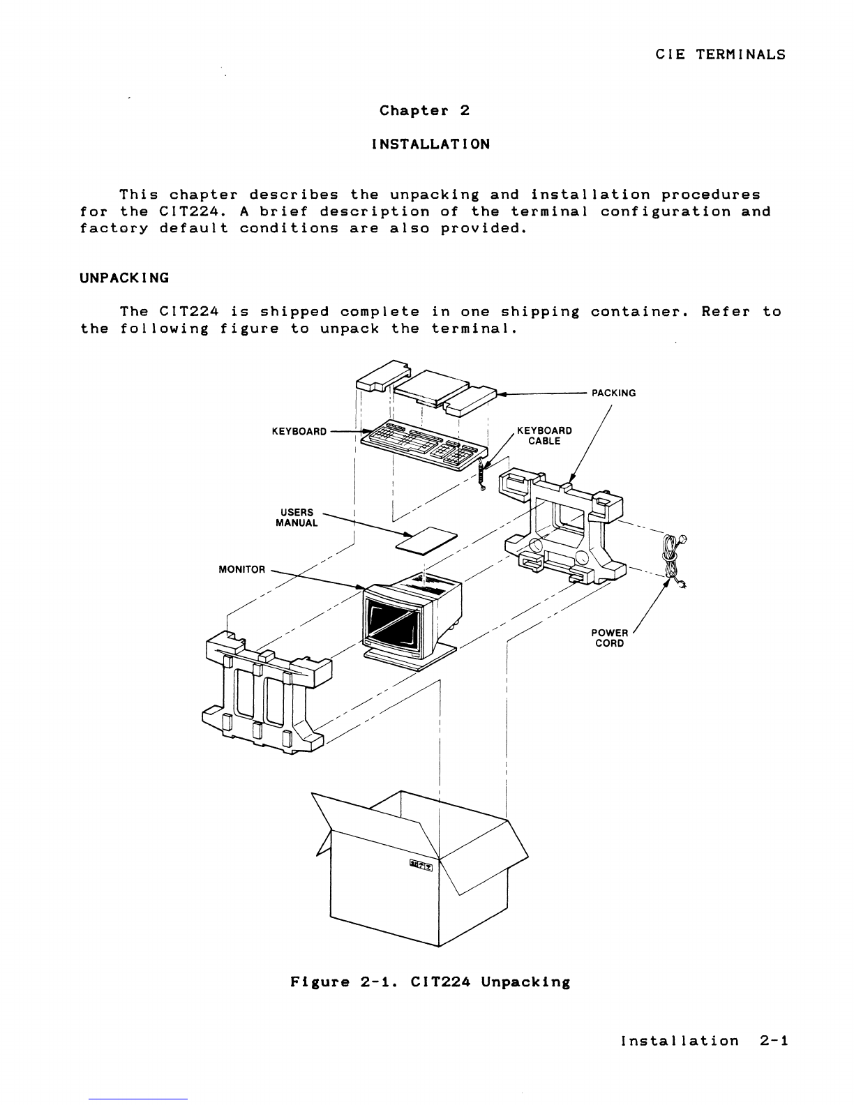
UNPACKING
The
CIT224
is
shipped
complete
in
one
shipping
container.
Refer
to
the
following
figure
to
unpack
the
terminal.
MONITOR
~"'"----'
~'--"/)_----
PACKING
KEYBOARD
--'-It"",
Figure
2-1.
CIT224
Unpacking
-1
POWER/
CORD
Installation
2-1

CIE
TERMINALS
INSPECTION
FOR
DAMAGE
Carefully
inspect
each
component
for
any
signs
of
shipping
damage.
All
shipping
containers
have
been
specially
designed
to
protect
their
contents
and
special
care
has
been
taken
to
prevent
damage
under
normal
shipping
conditions.
Mishandling
should
be
evident
upon
the
inspection
of
the
shipping
container.
If
damage
is
found
after
visual
inspection,
take
care
not
to
destroy
the
evidence.
If
necessary,
document
the
damage
with
photographs
and
contact
the
transport
carrier
immediately.
LOCATION
The
location
of
the
CIT224
in
a
working
environment
should
conform
to
the
environmental
operating
specifications
listed
in
Chapter
1.
However,
the
operational
reliability
of
the
terminal
requires
that
the
following
guidelines
be
adhered
to:
1.
Locate
the
terminal
so
that
there
is
free
airflow
through
the
top
and
bottom
air
vents.
2.
Do
not
place
working
materials
on
the
air
vents.
3.
Do
not
locate
the
terminal
where
it
can
be
exposed
to
direct
sunlight
or
intense
heat.
ELECTRICAL
CONNECTIONS
The
following
two
electrical
connections
must
be
made
in
order
to
operate
the
terminal:
The
coiled
keyboard
cable
The
AC
line
cord
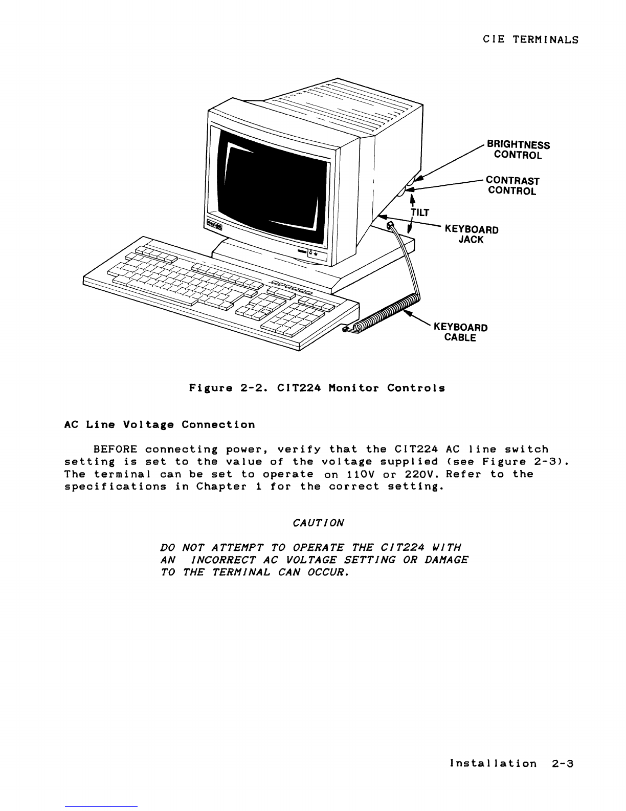
Keyboard
Cable
Attachment
Plug
the
keyboard
cable
connector
into
the
jack
located
at
the
lower
right
side
of
the
monitor
case,
refer
to
Figure
2-2.
2-2
Installation
CIE
TERMINALS
BRIGHTNESS
CONTROL
CONTRAST
CONTROL
KEYBOARD
JACK
KEYBOARD
CABLE
Figure
2-2.
CIT224
Monitor
Controls
AC
Line
Voltage
Connection
BEFORE
connecting
power,
verify
that
the
CIT224
AC
line
switch
setting
is
set
to
the
value
of
the
voltage
supplied
(see
Figure
2-3).
The
terminal
can
be
set
to
operate
on
110V
or
220V.
Refer
to
the
specifications
in
Chapter
1
for
the
correct
setting.
CAUTION
DO
NOT
A
TTEI1PT
TO
OPERA
TE
THE
CI
T224
WITH
AN
INCORRECT
AC
VOLTAGE
SETTING
OR
DAI1AGE
TO
THE
TERI1INAL
CAN OCCUR.
Installation
2-3
Table of contents
Popular Industrial Monitor manuals by other brands


Pentair
Pentair Raychem ECW-GF-DP Installation and operating instructions

Atlas IED
Atlas IED IP-DD Install Sheet

Advantech
Advantech IDS-3319 Series user manual

Acnodes
Acnodes APH 8064 user manual

Siemens
Siemens SIMATIC Industrial Flat Panel IFP2200 Product information

Delta Electronics
Delta Electronics Terminal Panels Series TP02G-AS1 instruction sheet


