Installation Guide
USP-070-B08, USP-070-C08, USP-070-B10,
USP-070-C10, USP-104-B10, USP-104-C10,
USP-104-M10, USP-156-B10, USP-156-C10
Unitronics’ UniStream®platform comprises control devices that provide robust, flexible
solutions for industrial automation.
This guide provides basic installation information for the UniStream®HMI Panel.
Technical specifications may be downloaded from the Unitronics website.
The UniStream®platform
comprises CPU controllers, HMI
panels, and local I/O modules
that snap together to form an
all-in-one Programmable Logic
Controller (PLC).
Expand the I/O configuration
using a Local Expansion Kit or
remotely via CANbus.
CPUs are Programmable Logic Controllers (PLCs), the heart of the
UniStream®platform.
The CPU-for-Panel cannot operate independently. It must be plugged
into the back of a UniStream®HMI panel. The panel provides the CPU’s
power source. The CPU-for-Panel comprises:
▪IO/COM Bus connector for interfacing Uni-I/O™ & Uni-COM™modules
▪Isolated RS485 and CANbus ports
▪Backup battery
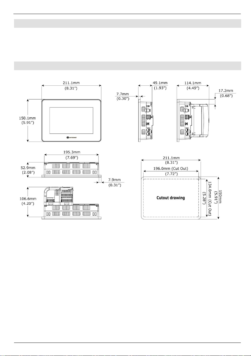
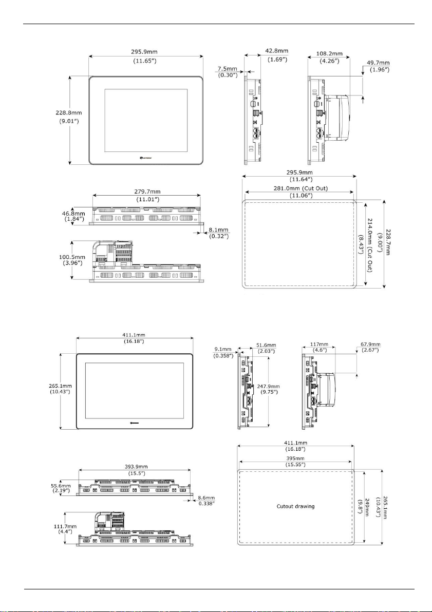
HMI Panels
Available in
different
dimensions
A high-resolution touch screen provides the operator interface for the
system and the physical foundation for a PLC+HMI+I/Os all-in-one
controller.
The DIN-rail structure on the panel’s back is designed to physically
support a CPU-for-Panel controller, Uni-I/O™ and/or Uni-COM™
modules.
Each panel comprises:
▪AUX connector to support the CPU
▪1 audio-out 3.5mm jack
▪1 microSD slot
▪2 type A, USB host ports and 1 Mini-B USB device port
▪2 Ethernet ports, RJ45, 10/100 Mbps
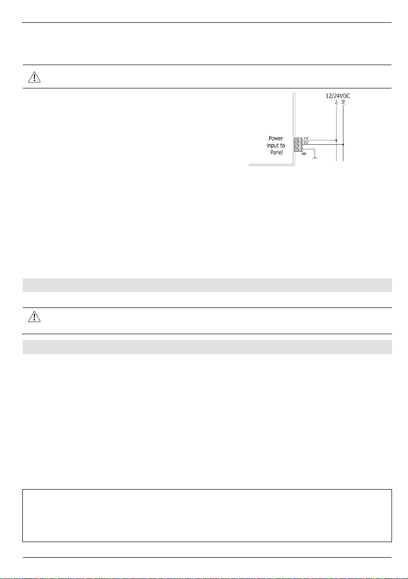
▪1 power input connector, 12/24 VDC
Integrate I/Os into your system by using:
▪On-board I/Os: snap onto the panel for an all-in-one configuration
▪Local I/O via a Local Expansion Kit
▪Remote I/O via EX-RC1
All-in-one UniLogic™ software, for hardware configuration,
communications, and HMI/PLC applications, available as a free
download from Unitronics web site.