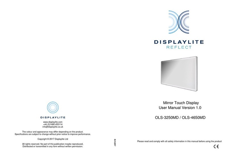
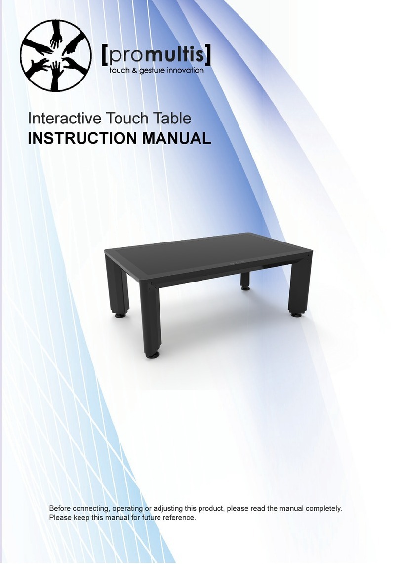
DISPLAYLITE DISPLAYLITE 180 User manual

Please read and comply with all safetyinformation in this manual before using the product.
Capacitive Touch Table
User Manual Ver. 1.1
DST-4600T
The colour and appearance may differ depending on the product.
Specifications are subject to change without prior notice to improve performance.
Copyright © 2016 Displaylite Ltd
All rights reserved, no part of this publication maybe reproduced,
distributed or transmitted in any form without written permission.
www.displaylite.com
+44 (0)1480 455114

VII Service
Charges may occur in cases where the customer requests service when the product
has no defects. Please read the manual in its entirety before contacting your service
provider for assistance. Solutions to common issues can be found in Trouble Shooting
on page 17.
Customer Service Center
Be prepared to provide your product model, serial number, and an explanation of the
encountered issue to the service provider. This will ensure you receive the most
accurate and efficient service possible.
Contact : DisplayLite Ltd
Huntingdon Business Centre
16 Blackstone Road
Huntingdon
Cambridgeshire
PE29 6EF
United Kingdom
Telephone: +44 (0)1480 455114
19
Email: [email protected]
Online: www.displaylite.com
Contents
I Before Using the Product
3 Safety Precautions
/ Symbols
/ Electrical Safety
/ Installation and Safety
/ Operation and Safety
/ Cleaning and Safety
IV Usage
V Trouble Shooting
VI Specifications
VII Service
II Preparation
III Connection: Media
Player, PC or Similar
/ PC Tray Disassembly
/ Cable Connection
/ PC Tray Re-Installation
02
7 Components
/ Main Box
/ Leg Box
8 Product Layout
/ Back Side
/ Left Side
/ Right Side
10 Unit Placement
/ Space
/ Installation Environment
/ Cable Connection
/ Location Optimization
11 Unpacking the Display
12 Installing the Product
/ Start
/ Configuration & Touch Calibration
/ Other
/ Shut Down
/ Screen
/ Audio
/ Touch Input
/ Product
/ Touch
/ Display
/ Power Status Explanation
/ Operating Device Requirements
Thank you for purchasing this Displaylite 180 interactive table, it is intended for general use such
as meeting rooms, banks, and restaurants. The product’s full user manual can be found at
www.displaylite.com. Please contact your supplier if you require more assistance.

18
Normal Operation
DPMS or Standby
Sleep Mode
Off Mode
Blue Light On
Blue Light Blinking
Blue Light Off
Blue Light Off
Power Status Explanation
Input Voltage
Input Frequency
Input Current
100V AC to 240V AC +/- 10%
50Hz to 60Hz +/- 3Hz
Max 3A (rms) (Excluding additional user Media Player/PC or other)
Electrical
Dimensions Fully Assembled
Weight Full Assembled
1182.6mm (L) x 760mm (W) x 950mm (H)
60Kg (Excluding Media Player, PC, or Similar)
Physical Information
Operating Temperature
Operating Humidity
Transportation Temperature
Transportation Humidity
Storage Temperature
Storage Humidity
0°C to 40°C
10% to 85%, non-condensing
-20°C to 60°C
5% to 85%, non-condensing
-20°C to 50°C
5% to 85%, non-condensing
Environmental
CB
UL
CE-EMC
FCC
IEC60950-1:2005 (2nd Edition);AM1:1999
UL60950-1, 2nd Edition, CSA C22.2 No.60950-1-07 ITE Safety part 1
EN55022:2010/AC:2011, EN55024:2010,
EN61000-3-2:2006/A1:2009/A2:2009, EN61000-3-3:2008
ANSI C63.4:2009, FCC Part 15 Subpart B (Class B)
International Approvals
I Before Using the Product
Safety Precautions
Warning
A serious or fatal injury may
result if instructions are not
followed.
Caution
Personal injury or damage to
property may result if instructions
are not followed.
Symbols
Electrical Safety
1.
2.
3.
4.
5.
6.
Do not touch the power cable with wet hands.
(Electrical shock may result.)
Do not use a damaged power cable or plug.
(Electrical shock or fire may result.)
Insert the power cable firmly into a ground terminal so it is not loose.
(Non grounded environments may cause a short circuit, resulting in
electrical shock.)
Ensure when connecting the product to a multi-outlet will not overload
the power source.
(Overloading may cause damage to connected products and overheated
sockets may cause fire.)
Do not bend or pull the power cable with force. Be careful not to leave
the power cord under a heavy object.
(Electrical shock or fire may result.)
Do not place the power cable near heat sources.
(Electrical shock or fire may result.)
03
7. Use only the power cable supplied with the product.
(Prevents incorrectly rated protection fuse being used, very long power
cable causing a trip hazard).

VI Specifications
Specifications are subject to change without notice to improve quality.
17
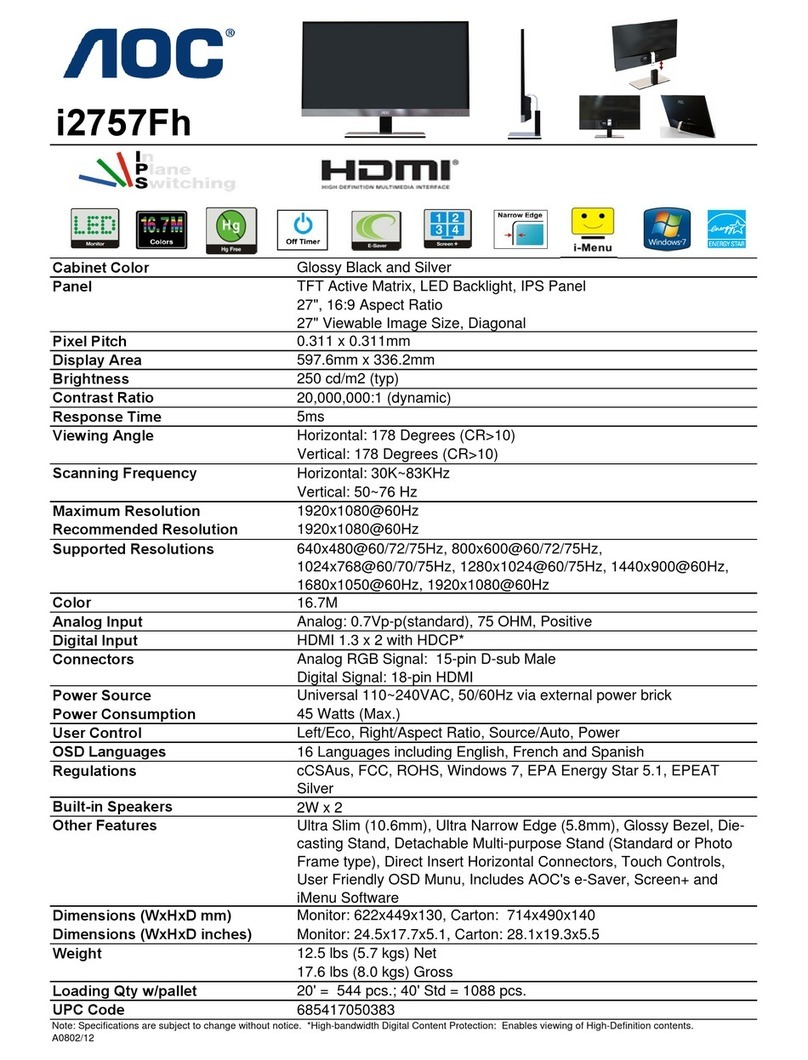
LCD Panel Manufacturer
LCD Screen Size
Resolution
Horizontal Frequency
Vertical Frequency
Active Area
Brightness
Contrast
Viewing Angle
Pixel Pitch
Maximum Input Video Signal
Number of Colours
Backlight
Max. Pixel Clock
Samsung Electronics Co., Ltd
46” (Diagonal)
1920 x 1080 Pixels
67.5 KHz
60 Hz
1018.08mm (H) x 572.67 (V)
Typ. 600cd/m (with touch glass)
Typ. 2800:1 (with touch glass)
178° (H) / 178° (V)
0.53mm
Full HD (1920 x 1080, 60Hz) with HDMI
16.7M (8 bits)
Edge LED (Light Emitting Diode) BLU
150 MHz
Display
Touch Method
USB
Available Touch Points
Response Time
Accuracy
Jitter
SNR
Channels
Transmittance
Haze
Linearity
Projected Capacitive Touch
2.0 (or greater)
10
8ms
2mm
1mm
31dB
123 (Tx) x 71 (Rx)
82 +/- 2%
<= 5%
+/-0.5mm (V), +/-0.5mm (H), +/-2mm (D)
Touch
Channels
Power
Frequency Response
Digital Audio Input Channel
2 (Stereo)
25 Watts (rms)
10Hz to 20KHz
24bit, 48KHz, PCM
Audio
Memory
Processor
Windows (7, 8, 10), Android 6.0
Mac OS.x up to 10.9 supports 10 touch points (2 finger gestures only)
Mac OS.X 10.10 / 10.11 supports 2 touch points only
Linux Kernel 3.1 supports 10 touch points (builds may vary)
4GB or higher
Intel i5, equivalent or higher
Operating Device
Compatible OS
Installation and Safety
Operation and Safety
1.
2.
3.
4.
5.
6.
Do not install the product on an unstable surface or area.
(The product may become damaged or malfunction.)
Do not install the product in an area exposed to water or other
sources of moisture.
(Electrical shock may result. Please refer to the environmental
guidelines in the user manual.)
Ensure the product is moved by at least two people.
(The product is heavy and may become damaged if dropped
or caused personal injury.)
Do not place the product near a heat source.
(Fire may result.)
Contact your supplier or a specialised company to properly
install your display on a wall (if not using as a table).
(Non-specialists may damage the product or property. When
mounting, only use hardware and fixings designed for the purpose.)
Do not let children approach when installing the product.
(There is a risk of personal injury and product damage.)
1.
2.
3.
Do not climb on the product or place a heavy object on top of the
product.
(The product may become damaged or cause personal injury.)
Never disassemble, repair or modify the product yourself.
(By doing so, you void any responsibility for repair or service by
the manufacturer and supplier. Opening the product puts you
at great risk of electrical shock, and may result in product
damage. Contact your supplier for repairs.)
Do not push the product or drop items on it with force.
(The product may become damaged or malfunction.)
04

16
V Trouble shooting
Before requesting customer service, test your product as follows.
If the problem persists, contact the customer service center.
Screen
1.
2.
Nothing appears on the screen.
> Ensure the power code is connected.
> Ensure the main power switch in the “I” setting.
> Ensure the power button is on.
> Ensure the connected device is powered and on.
The images on the screen appear distorted or shaky.
Audio
1. There is no sound or volume is low.
Touch Input
1.
2.
Touch input is not working well.
> Restart the device or restart the display.
> Confirm touch is calibrated.
Ghost touches appear without any touch input from user.
> Ensure the product is connected to a grounded power source.
> Static electricity may build up and cause unwanted touches.
Ensuring the product is properly grounded will help alleviate this issue.
> Ensure the HDMI cable is connected securely.
> Confirm the video output settings of the device.
> If any video cable adapters or repeaters are used it is possible
for image degradation or image signal loss to occur.
> Confirm whether the resolution and frequency of the graphics
card are compatible with the product.
> Check the HDMI connection of the HDMI cable.
> Check the device’s OS audio output settings.
> Check the audio settings of the software currently in use.
4.
5.
6.
7.
8.
9.
10.
11.
Ensure that the product’s vents are not blocked.
(An increased internal temperature may damage the product or
may cause a fire.)
Be careful not to strike the edges of the table.
(The product profile may become damaged or personal injury
may result due to the impact.)
Turn off the power switch and disconnect the power cable and all
other connected cables before moving the product.
(Damaged cables may cause electrical shock and people may trip
over the cable, causing personal injury.)
Do not insert metallic objects (knives, hairpins, etc.) or flammable
objects (paper, matches etc.) into the product’s vents or input/output
ports, etc. Only connect with compatible cables and devices.
(Product failure, electrical shock or fire may result.)
Power off the product and remove the power cable during lightning
or thunderstorms.
(Electrical shock or fire may result.)
Do not pull on the cable only when disconnecting the power cable
from the power socket.
(Damaging the power cable may result in electrical shock or fire.)
Do not put a hot or heated object on top of the product.
(Product failure, electrical shock or fire may result)
Disconnect the power cable from the power socket when not in
use for extended periods of time.
(Dust accumulation can cause electrical shock or fire.)
Operation and Safety
05
12. Stop operating the product if you become aware of unusual behaviour
such as smokre, strange sounds, smells, etc.
(Continued use after noticing unusual behaviour may result in further
damage to the product, environment, or personal injury).

IV Usage
Before using the product, please check the I/O switch on the side of the product.
This switch controls power for the entire unit. In the “O” setting, neither the Display
or Device Power Port will receive power. In the “I” setting, the Device Power Port
will remain constantly powered and the display can be turned on using the power
button.
Set the I/O switch to the “I” setting. Push the Power Button inward and release.
A blue light will emit to indicate the display is now on. Wait a few seconds for the
display to power on fully. The contents of your Mini PC or Android device should
be displayed on the screen after a few moments. If the device does not appear
on the screen check the power status of the device, as it may not be powered on.
Start
Once the product’s Display and connected device are powered on, you may
operate the product. Touch should be calibrated automatically, as the table is
designed to be plug and play. If touch is calibrated improperly, please perform
a calibration using the touch calibration settings in Windows:
1. Open Windows Control Panel.
2. Open Tablet PC Settings and select calibrate.
3. Follow the Windows prompts and touch the screen to calibrate according to Windows.
Touch calibration for Android and other devices will vary. Consult your device manual
for details on how to calibrate touch. The product’s speakers are set to operate
at 90% of their maximum output. To adjust the volume, you must utilize the audio
output controls in Windows or those of your connected device.
Configuration & Touch Calibration
Touch and visual performance depend greatly upon the specifications of the
connected device. Be sure that your device meets the minimum requirements
outlined in the product specifications on page 18.
Other
15
The Display and operating Mini PC or Android device must be turned off
separately. First, shut down the Mini PC or Android device by using the OS
menu. To shut down the display, press the round power button. You may leave
the I/O switch on in the “I” setting if desired. If the Mini PC or Android device
needs to run while the Display is shut down, the I/O switch must remain in the
“I” setting. This is useful for performing upgrades or service on the device
without the need for the Display to remain powered on.
Shut Down
Cleaning and Safety
1.
2.
3.
4.
5.
Power off the product and remove the power cable. Pull the
power cable by the plug and never touch with wet hands.
(Electrical shock may result.)
Wipe the product’s screen using a clean, soft, dry cloth.
(Otherwise product scratching may result).
Use a moist soft cloth and wring thoroughly before wiping
to clean the exterior of the product.
(Otherwise damage may result).
Do not use detergent that contains alcohol or other solvents.
Use cleaning solvents intended only for computer displays.
(Damage to the product surface may result).
Connect the power cable to the product after cleaning the product
and drying completely.
(Product failure, electrical shock or fire may result).
06

III Connection: Media Player, PC or Similar
Mini PCs, Android boxes and other devices can be connected to operate the table.
These devices are not included with the product and must be purchased separately.
Users should also refer to the device’s manual during installation.
14
Assembly 1. Components
PC Tray
USB
Plates
To install the PC or operating device, first remove
the table’s PC Tray. The PC Tray must be removed
in order to access the device power supply and
connection ports. Remove the PC Tray screw and
slide the Tray toward the end of the table to release
the tray’s hooks from the table’s grooves. 2 holes are
provided for optional chassis mount USB cables.
These holes are covered but can be exposed by
removing the USB plates shown in the diagram. The
USB cables are not supplied.
Connect the device’s power cable to the Power Port.
Connect the device’s HDMI output to the HDMI Port
for video and audio transmission. Connect one of the
device’s USB ports to the Touch USB Port for touch
input communication. Set your Media Player, PC or
similar to auto power on when mains power is applied.
Power Port HDMI Port Touch USB Port
After connecting the device cables, re-attach the PC
Tray to store the device and cables. With the device
and cables resting in the tray:
A - Raise the PC Tray hooks into the grooves
and slide inward.
B - Secure using the PC Tray Screw.
A
BPC Tray
Table
II Preparation
Before unpacking the product, familiarize yourself with the product components and layout.
After Unpacking the Display (Section 4), confirm that all components were received and are
free of damage.
Contact your customer service center if any components are missing.
The images below may differ from the components you receive.
Smart Display (1EA) UK Power, EU Power,
USB, HDMI (1EA)
Quick Start Guide
Leg Braces (4EA)Table Legs (4EA)
1A, 1B, 2A, 2B
07
Leg Plate (2EA)
1, 2
PH M4x10 SEMS
(8EA)
FH, M5x12
(32EA)
Acrylic Finishing Strips (4EA)
Screw “A” Screw “B”
FH, M3x12
(10EA)
Screw “C”
Main Box
Leg Box
QUICKSTART GUIDE - VER. 1.0 SAFETYGUIDE - VER. 1.0
Safety Guide

5
Complete Section 5 by using 6 x B screws in each leg
plate. There are 3 screw holes around each leg. Using
A screws, attach the 4 Leg Braces to the display.
Screws should be hand tight. Secure cables with
supplied cable clamps and screws as shown.
A
B
6
Caution! With 2 or more people, place the product
upright. At this point you may connect the power
cable from Leg 1A to the product’s Power Input port.
The final step in assembly is to affix the acrylic
finishing strips to the leg exteriors. 1 strip should
be affixed to each leg. The mounting grooves can
be found where the legs face the left and right ends
of the product. Each strip has been treated with an
adhesive. Remove the backing paper completey
and affix 1 strip to each leg.
7
8
Cable Clamp
13
Align the leg plate holes with the corresponding
holes in the display. Affix legs 1A and 1B on the side
with the power swtich (right). Affix legs 2A & 2B on the
side with the device HDMI and USB ports (left). Use
5 x C screws to attach each plate. Screws should be
hand tight.
1A
2A
2B
1B
C x 5
C x 5
2. Product Layout
08
Design is subject to change without notice to improve performance and quality.
Back Side
Speaker Hole
Speaker Hole
Fan Vents
PC Tray Mount
Table Legs
Multitouch Display
Display Power
Front
Power Cable
PC Tray
Mini PC / Android Box

If the product’s operating Device requires a cabled
network connection, or external video output, you may
route these cables through leg 2A or 2B. Simply
remove the 3 screws holding the leg’s rubber foot,
and feed the cables through the leg. Route them
through the cable hole and re-attach the rubber foot.
Cable end for
Mini PC/Android
Cable end for
external connection
Leg Top
Leg Bottom
12
5. Installing the Product
Attach Legs 1A and 1B to Leg Plate 1. Use 5 x B
screws per leg. Leg 1A comes with the product’s
power cable pre-installed. Caution! Be careful not
to pinch it when assembling the legs to the leg plate.
Screws should be hand tight.
1A
1B
Plate 2
Plate 1
2A
2B
Attach Legs 2A and 2B to Leg Plate 2. Use 5 x B
screws per leg. Screws should be hand tight.
Affix Leg Braces to Legs 1A, 1B, 2A, and 2B
using A screws. The attachment point can be
found at the tops of the legs near the leg plates.
Screws should be hand tight.
B x 5
B x 5
B x 5
B x 5
A
Leg Brace
09
Left Side
Right Side
*Device Power Port HDMI Port Touch USB Port
Power Cable Port I/O Switch
<Device Connection>
<Display Power>
Note: Product ships with a PC Tray which must first be removed in order to
access the Device Power Port.
Power Service
*The status of the Device Power Port is controlled by the I/O switch. To power down
the operating PC/Android system use the device’s OS controls or the main I/O Switch.
Device Power Port Power for Mini PC / Android device (110V~240V). 50/60Hz @ 3.5A
HDMI Port Video & Audio input for device.
Touch USB Port USB port for touch communication to device.
Power Cable Port: Connected to the power cable in Leg 1A.
I/O Switch Mains power switch. Controls the power status for the entire product.
Power (Button) Controls the power status of the display panel and speakers.
Service This cover should never be removed by you, the customer, or any other
users of the product. It is intended for use by qualified professionals only.

Check all safety precautions before installing the product. All environmental factors
(unit placement,power supply,etc.) outlined in this manual must be adhered to fully.
In situations where users do not adhere to cautions and warnings, personal injury
or property damage may result.
4. Unpacking the Display
11
Caution! With 2 or more people, move the box
into the area where the product will be installed.
Prepare a soft surface to lay the display face down
in order to prevent any scratches or damage. Ensure
you have enough space so that you may lay the
display flat on its front face.
Remove any banding or plastic wrapping from
the box. Remove the 4 interlock handles and
lift the Main Box directly upward and
away from the unit.
Remove the Upper Cushions (L & R). Remove
the Product Bag. You may remove the display’s
Protective Film at this time or do so after you
have completed assembly.
Caution! With 2 people lift the display upward,
away from the Lower Cushions (L & R) and the
Bottom Box. Gently place the display glass
downward onto a soft surface in the area
you have prepared to perform the
installation.
Bottom Box
Protective Film
Display
Product Bag
Upper Cushions
Main Box
Lower
Cushions
Interlock Handles
You should install the product in an area where it may be used safely and
comfortably. Unit placement should satisfy the following qualifications.
Install the product ensuring enough space for multiple users.
Please provide enough space for users to sit or stand at all edges of the table.
- Enough space to accommodate the size of the product.
- Enough space to approach from all sides without any limitations.
- Enough space to interact around the display without feeling any discomfort.
3. Unit Placement
Space
Make sure that there are no heating or air conditioning ducts near the product.
sudden temperature changes may disrupt the product.
- Make sure the intake and exhaust vents are not blocked or impeded.
Consider the product’s visibility, environmental cleanliness, and noise.
- Install the product in a location where users can easily access it.
- Use the product in a clean, unobstructed environment.
- Clean the product and its surrounding environment regularily.
- Eliminate or reduce the volume of any background noise competing with the product.
Installation Environment
Location Optimization
Besides power, you may need to connect network cable and other external devices.
After preparing proper cables and connections, make sure that there is enough
space to connect all required cables.
Electrical power
A power cable is included for connecting the product. Consider the distance between
the table and power source, cable length, and routing when choosing your location.
Route the power cable safely. People may fall or trip on the cable, causing damage
or personal injury. Only use the power cables that were provided with the product.
If the power cable and power mains in the install location are not compatible, please
contact your service representative or qualified electrician. Do not use a non-standard
power supply.
Cable Connection
10
- Consider that the product’s noise or noise from users may interfere with other
occupants of the surrounding environment.
- Place the product giving consideration to hallways or traffic corridors.
This manual suits for next models
1
Table of contents
Other DISPLAYLITE Monitor manuals
