Distech Controls Allure ECW-Sensor Series User manual

Allure ECW-Sensor Series
Figure1: Allure ECW-Sensor Series Sensor (Allure ECW-Sensor-SOF model)
Product Description
The Allure™ ECW-Sensor series are wireless battery-less room temperature sensors designed to communicate with Open-To-Wireless ready controllers
via radio telegrams in accordance with the EnOcean standard. These sensors provide accurate local temperature measurement with the capability of lo-
cal setpoint adjustment, fan speed setting, and occupancy override. Equipped with solar cells, they utilize energy converted from natural and artificial
light for their daily operation.
The modern alluring profile enclosure of an Allure ECW-Sensor is suitable for classrooms, hotels, executive areas, office spaces and other commercial
areas. With a separate sub-base, this device can be easily installed on almost any type of surface using double-sided adhesive tape or wall screws.
This document describes the hardware installation procedures for the following devices: Allure ECW-Sensor, Allure ECW-Sensor-O, Allure ECW-Sensor-
S, Allure ECW-Sensor-SO, and Allure ECW-Sensor-SOF. All models are available in the 902MHz and 868MHz frequency bands.
Unless otherwise indicated, the term Allure ECW-Sensor will be used in this document to represent all the models of the Allure ECW-
Sensor Series.
General Installation Requirements
For proper installation and subsequent operation of the Allure ECW-Sensor, pay special attention to the following recommendations:
£Upon unpacking, inspect the contents of the carton for shipping damages. Do not install a damaged device.
£The device is designed to operate under the following environmental conditions:
– Ambient temperature from 41°F to 104°F (5°C to 40°C)
– Relative humidity from 0% to 95%, non-condensing
£Ensure proper ventilation of the device and avoid areas where corroding, deteriorating or explosive vapors, fumes or gases may be present. The de-
vice must be oriented with the ventilation slots towards the top to permit proper heat dissipation.
Any type of modification to any Distech Controls product will void the product’s warranty
Take reasonable precautions to prevent electrostatic discharge to the device when installing, servicing or during operation. Discharge
accumulated static electricity by touching one’s hand to a well-grounded object before working with the device.
Installation Guide

2 / 8
Maintenance and Cleaning
Gently clean the device with a soft, lint-free cloth slightly moistened with a solution of mild liquid dish soap and warm water or disinfect the device with a
soft cloth slightly moistened with a 70% isopropyl alcohol.
Do not directly spray any liquid or disinfecting solution on the device. Do not clean with any other chemicals products.
Mounting Instructions
The Allure ECW-Sensor has been specially designed for easy installation. However, certain conditions apply when choosing a suitable location for the
device:
£Install the device in a location of average temperature approximately 5 ft (1.5 m) above the floor
£The device should not be installed on an exterior wall.
£The device should not be installed near a heat source.
£The device should not be installed near an air discharge grill.
£The device should not be installed in a place where it can be affected by the sun.
£Install the device in an area that provides proper device ventilation. Nothing must restrain air circulation to the device.
The Allure ECW-Sensor has not been designed for outdoor use.
The Allure ECW-Sensor can be mounted on a wall using screws or double-sided adhesive tape.
Before installation, verify that local communication regulations allow the operation of wireless devices that communicate at a frequency of
902 or 868MHz. For more information on transmission norms in different countries, refer to the Open-to-Wireless™ Application Guide.
For the 868MHz model only:
£Center frequency: 868.3MHz
£Occupied frequency band: 868.0 - 868.6MHz
£Maximum transmission power: 3dBm
For the 902MHz model only:
£Center frequency: 902.875MHz
£Occupied frequency band: 902.7-903.0MHz
£Maximum transmission power: 1dBm
Wall Mounting with Tape
The Allure ECW-Sensor can be mounted on almost any type of surface using double-sided adhesive tape. Simply apply the tape to the back of the de-
vice first and then stick it to the desired spot on the wall.
Figure2: Mounting using double-sided adhesive tape
Wall Mounting with Wall Screws
The Allure ECW-Sensor can also be mounted using wall screws:
1. Open the sensor by separating its front and back plates.
2. Use the mounting holes on the back plate to mark the location of the holes that need to be drilled.
3. Remove the back plate and drill the holes.
4. Clean the newly drilled holes, insert some wall anchors, and then fasten the back plate using the appropriate screws.
5. Re-attach the sensor to the back plate.

3 / 8
Figure3: Mounting using wall screws
Associating with the Receiver
Once the Allure ECW-Sensor is installed, it must be associated with the receiver it will communicate with. Association with the receiver can be done in
one of the following two ways:
1. Manually – Enter the sensor’s module ID into the receiver’s configuration menu (or controller’s wireless input settings).
2. Automatic learning – Use the Learn button so that the receiver automatically detects and identifies the sensor. When the Learn button is pressed, a
teach-in telegram is sent to the receiver with information on the sensor’s profile, type, and manufacturer ID.
The 868MHz model is a category 2 receiver.
For the 868MHz model only:
£Center frequency: 868.3MHz
£Occupied frequency band: 868.0 - 868.6MHz
£Maximum transmission power: 3dBm
For the 902MHz model only:
£Center frequency: 902.875MHz
£Occupied frequency band: 902.7-903.0MHz
£Maximum transmission power: 1dBm
For more details on how to perform the above two procedures on Distech Controls’ Open-To-Wireless ready controllers, refer to the appropriate product
user guides.
Figure4: Location of the Learn button

4 / 8
Device Dimensions
Unit Legend:
Inches (mm)
Table1: From top left to bottom: Front view, back plate, side view – Maximum possible dimensions of Allure ECW-Sensor with added extension modules
Setting the Transmission Interval
The Allure ECW-Sensor contains four jumper pins that set the transmission interval. These jumper pins are located beside the Learn button and are ac-
cessible through the hole in the sensor’s back plate.
Figure5: Location of jumper pins at the back of the sensor and their different settings
The transmission interval has a direct influence on the sensor’s solar energy discharge while in operation.
The factory default jumper setting is the recommended setting:
£CW = 100 sec (JP1)
£CP = 7-14 (JP4)
See the performance parameters in the Redundant Transmission (CP) [pg. 5] section of this document for more information about
how these jumper settings affect sensor performance.
Check your local regulations before changing the jumpers from the factory default setting.
Wake-Up Cycle Time (CW)
The first pair of jumper pins, JP1 and JP2, are used to set the sensor’s wake-up cycle time (CW). After CW, the sensor transmits a radio telegram to the
receiver only if the:
£Temperature reading has changed by >0.8°C since last transmission.
£Setpoint has been adjusted by an angle >14° since last transmission.
£Fan speed position has been changed since last transmission.
CW can be 1, 10, or 100 seconds, depending on how the first pair of jumper pairs are set (Figure 6 1).
Keep in mind that when the Learn button or override button (certain models) is pressed, a radio telegram is immediately transmitted.
A radio telegram contains information on sensor input data, such as temperature and setpoint, as well as the sensor ID.

5 / 8
Redundant Transmission (CP)
The second pair of jumper pins, JP3 and JP4, are used to set the number of consecutive cyclic wake-up times (CP) that are allowed without transmission
of a radio telegram; in such a case a redundant signal is transmitted. Redundant retransmission refers to the transmission of a radio telegram when no
significant input change has taken place since last transmission.
CP can be any number from 1 to 140, depending on how the second pair of jumper pins is set (Figure 6 1).
Examples
£CW = 100 sec, CP = 10
Redundant transmission takes place every 100 X 10 = 1000 sec. (approx. 16 minutes, when there is no input change)
£CW = 100 sec, CP = 100
Redundant transmission takes place every 100 X 100 = 10000 sec. (approx. 2 hours and 45 minutes, when there is no input change)
The following performance parameters have been calculated to show the different results (approximate values) according to the different jumper settings.
Wake cycle [s] (CW
Jumper)
Transmit Interval [s] (CP
Jumper)
Operation Time in darkness
[h] when fully charged
Required recharge time [h]
at 200 lux within 24h for
continuous operation
Constant illumination re-
quired [lux] for continuous
operation
1
(No jumper)
1
(No jumper)
0.4 Insufficient lux
Use a battery
Not applicable
1
(No jumper)
7-14
(JP4)
1.4
1
(No jumper)
70-140
(JP3)
1.7
10
(JP2)
1
(No jumper)
4
10
(JP2)
7-14
(JP4)
13 24 200
10
(JP2)
70-140
(JP3)
16 20 170
100
(JP1)
1
(No jumper)
34 10 80
100
(JP1)
7-14
(JP4)
80 4 80
100
(JP1)
70-140
(JP3)
90 4 80
Table2:
Performance Parameters by Jumper Settings
N.B. The shaded row indicates the factory default jumper setting, which is the recommended jumper setting. For non-factory default jumper settings,
check with local regulations for compliance with radio-spectrum use requirements.
Transmission Range
The main factors that influence the system transmission range are type and location of the antennas of the receiver and the transmitter, type of terrain
and degree of obstruction of the link path, sources of interference affecting the receiver, and “dead” spots caused by signal reflections from nearby con-
ductive objects. Since the expected transmission range strongly depends on this system conditions, range tests should categorically be performed before
notification of a particular range that will be attainable by a certain application.
Radio signals are electromagnetic waves; hence the further they travel, the weaker the signal becomes and the range is limited. The coverage is further
decreased by specific materials found in the direction of the transmission. For example, while radio waves can penetrate a wall, they are dampened
more than if the waves were on a direct line-of-sight (LoS) path.
The following table shows the different types of walls and range reduction:
Material Range Reduction vs. LoS
Wood, drywall, glass (uncoated, without metal) 0 – 10%
Brick, particle board 5 – 35%
Metal, ferro concrete, mirrors 10 – 90%
Metallic obstructions such as wall reinforcements, machinery, metal office furniture (large filing cabinets), etc. are major sources of field strength reduc-
tion, but small metal studs on a gypsum dry wall do not show a recognizable screening. Furthermore, fire-safety walls, elevator shafts, stairwells, and
supply areas should be considered as complete transmission screens. In addition, the angle with which the transmission travels through the obstructions
has a major influence on the field strength. The steeper the angle through an obstruction the more the field strength dampens. Therefore, it is preferable
that the transmission should be arranged so that it travels straight and perpendicularly through the obstruction. Wall niches should be avoided as well.
Other factors that restrict transmission range include:
Important objects and factors that decrease or constrain coverage:
£Metal separation walls or hollow lightweight walls filled with insulating wool on metal foil
£Inserted ceiling with panels made of metal or carbon fiber
£Steel furniture, glass with metal coating (typically not used indoor)
£Switch mounted on metal surfaces (typically 30% loss of range)
£Metallic switch frames (typically 30% loss of range)

6 / 8
The distance between EnOcean receivers and other transmitting devices such as computers, audio and video equipment that also emit high-frequency
signals should be at least 1.6 ft (0.5 m).
Electronics that communicate wirelessly within the same frequency bandwidth will add noise and disturbances to the transmissions
between the sensor and the receiver and will therefore further reduce the transmission range.
For more information about the EnOcean and Open-to-Wireless technologies, refer to the Open-to-Wireless Solution Application Guide. For more infor-
mation about the Wireless Receiver module, refer to the Wireless Receiver Datasheet. These documents can be found at www.distech-controls.com.
Wireless Equipment Mounting Instructions
Preserving Signal Strength
When installing the wireless equipment, it is important to ensure that distances and obstructions do not impede transmission. Metallic parts, such as rein-
forcement in walls, machinery, office furniture, etc. are major sources of field strength dampening. Furthermore, supply areas and elevator shafts should
be considered as complete transmission screens (See the next figure for radio wave screening). As a rule of thumb and in normal conditions, the equip-
ment will transmit over a range of up to 100 ft (30 m) for both 868MHz and 902MHz models.
Sheet
Metal
Tx: Transmitter Rx: Receiver
Figure6: Screening of radio wave
Signal Transmission Quality Testing
Even under screening conditions, Distech Controls strongly recommends that you always test the signal strength regardless of the range distance be-
cause radio signals and transmission range can vary according to building and office setup. To verify the signal strength in any installation, use the RSSI
feature with EC‑
gfx
Program.
For more information on how to test signal strength, refer to the Open-to-Wireless Solution Application Guide. For more detailed information on the RSSI
feature, refer to the EC-
gfx
Program User Guide.
Transmission Obstructions and Interference
In addition to obstructions, the angle with which the transmission travels through the obstructions has a major influence on the field strength. So the
steeper the angle through an obstruction the more the field strength dampens. Therefore it is preferable that the transmission be arranged so that it trav-
els straight and perpendicularly through the obstruction.
High Penetration Angle
Tx: Transmitter Rx: Receiver
Figure7: Angle of radio wave
The sensor mounting location should not be on the same wall or plane as the receiver. Radio waves are rather subject to interfering leaks or reflections.
Side or opposite walls are better locations.

7 / 8
Tx: Transmitter Rx: Receiver
Figure8: Radio wave along the wall
It is also recommended that a wireless receiver and sensor not be placed directly below or on top of each other; for example, if a wireless receiver is
placed in the ceiling then the sensor should not be placed on the wall just below the ceiling, on the same vertical axis as the receiver. The sensor or the
receiver should be relocated to obtain a better transmission range.
Tx: Transmitter Rx: Receiver
CEILING
FLOOR
Side View
Relocate sender or
receiver
Relocate sender or
receiver
Both the sender and
receiver should NOT
be on the same axis
Figure9: Wireless Receiver Ceiling Installation
Unrelated transmitters should be more than 6.5 ft (2 m) away from the receiver to avoid possible interference (cell phone, GSM/DECT, WiFi, cordless
phones, RFID reader).
Repeaters
Repeaters are wireless devices that help deal with the transmission problems that were mentioned previously. A repeater receives transmissions and re-
sends an amplified signal to the receiver. The transmission range can thus be increased and obstacles can be bypassed, as illustrated in the next figures
about repeaters.
Sheet
Metal
Tx: Transmitter Rx: Receiver Receiver
Figure10: Use of repeaters to bypass obstructions
High Penetration Angle
Tx: Transmitter Rx: Receiver Receiver
Figure11: Use of repeaters to avoid unfavorable penetration angle

8 / 8 Allure ECW-Sensor Series_IG_16_EN
Mounting Considerations for Solar Energy Storage
The Allure ECW-Sensor possesses solar cells that use energy converted from natural and artificial light for their daily operation. As supplied, it is opera-
tional. However, it may be necessary to recharge the solar cell accumulator after an extended time in darkness. In principle, the recharging process is
done automatically when the device is removed from its packaging and exposed to daylight. When set at the recommended jumper settings, the recharg-
ing process can also take place while in operation (at an environment where light is available for 7 hours at 200lx), and would take up to 3 consecutive
days. Keep in mind that the device may take some time to charge (15 - 30 minutes) before it can transmit its first signal. Once the device is fully charged,
maintaining the charge would only require a daily exposure of 4 hours at 200lx, regardless of whether artificial or natural light is used. For more informa-
tion on charging durations and required brightness levels, refer to the Open-to-Wireless Solution Application Guide.
To meet special requirements concerning correct and sufficient ambient brightness, it is necessary to observe certain basic conditions when selecting the
mounting location:
£Total illumination must not exceed 1000lx for long periods.
£Most health and safety workplace standards require a minimum illumination of 500lx in office workplaces.
£When illuminating the sensor with direct artificial light such as spotlights, the angle of incidence relative to the solar cell should not be too steep.
£Placing the sensor under direct sunlight must be avoided if it leads to inaccurate temperature measurements caused by heating from the sunlight.
£The sensor should be positioned in such a way that no obstructions come between it and the light source.
£An increase in the sending rate of the sensor will require more energy and thus more illumination. Refer to Table 6 1 for the recommended and de-
fault jumper settings.
For more detailed information regarding the charging time and specifications, refer to the Open-to-Wireless Application Guide.
Using a Battery as Backup
For installations where there is insufficient ambient light or where the Allure ECW-Sensor is in prolonged darkness, it is recommended to use a
3.6V/1.1Ah Lithium battery (Type ER 14250; 1/2AA). The battery is only used as a backup during the absence or lack of light.
To install a battery in the Allure ECW-Sensor, open its cover and place the battery into the battery holder.
Figure12: Installing a battery
FCC Statement
Changes or modifications not expressly approved by Distech Controls could void the user's authority to operate the equipment.
This equipment has been tested and found to comply with the limits for a Class B digital device, pursuant to Part 15 of the FCC Rules.
These limits are designed to provide reasonable protection against harmful interference in a residential installation. This equipment
generates, uses and can radiate radio frequency energy and, if not installed and used in accordance with the instructions, may cause
harmful interference to radio communications. However, there is no guarantee that interference will not occur in a particular installation. If
this equipment does cause harmful interference to radio or television reception, which can be determined by turning the equipment off and
on, the user is encouraged to try to correct the interference by one or more of the following measures:
£Reorient or relocate the receiving antenna.
£Increase the separation between the equipment and receiver.
£Connect the equipment into an outlet on a circuit different from that to which the receiver is connected.
£Consult the dealer or an experienced radio/TV technician for help.
£Duty cycle regulation: 1 radio packet of a transmitter should not be sent within 6.5 seconds of the previous one.
This device complies with Part 15 of the FCC rules and with Industry Canada’s license exempt RSS. Operation is subject to the following
two conditions:
£This device may not cause harmful interference, and
£This device must accept any interference received, including interference that may cause undesired operation of the device.
©, Distech Controls Inc., . All rights reserved.
Images are simulated. While all efforts have been made to verify the accuracy of information in this manual, Distech Controls is not responsible for damages or claims arising from the use of this manual.
Persons using this manual are assumed to be trained HVAC specialist / installers and are responsible for using the correct wiring procedures and maintaining safe working conditions with fail-safe environ-
ments. Distech Controls reserves the right to change, delete or add to the information in this manual at any time without notice.
Distech Controls, the Distech Controls logo, Open-to-Wireless, Innovative Solutions for Greener Buildings, and Allure are trademarks of Distech Controls Inc. BACnet is a registered trademark of ASHRAE.
Global Head Office - 4205 place de Java, Brossard, QC, Canada, J4Y 0C4 - EU Head Office - ZAC de Sacuny, 558 avenue Marcel Mérieux, 69530 Brignais, France
This manual suits for next models
1
Table of contents
Other Distech Controls Control System manuals
Distech Controls
Distech Controls EC-BOS-6AX Programming manual
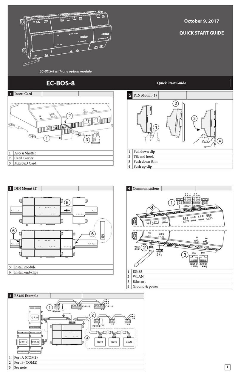
Distech Controls
Distech Controls EC-BOS-8 User manual
Distech Controls
Distech Controls ECLYPSE APEX User manual
Distech Controls
Distech Controls DA-020S Series Manual
Distech Controls
Distech Controls Allure EC-Smart-Comfort Series User manual
Popular Control System manuals by other brands

Whelen Engineering Company
Whelen Engineering Company Traffic Advisor TACTLD1 Installation and operating guide
Vicon
Vicon PILOT PLUS V1544 Installation and operation manual
Buderus
Buderus Logamatic 2107 operating instructions

Bimba
Bimba PCS user manual

Pilz
Pilz PMCprimo C2 operating manual
Bender
Bender NGRM500 manual
