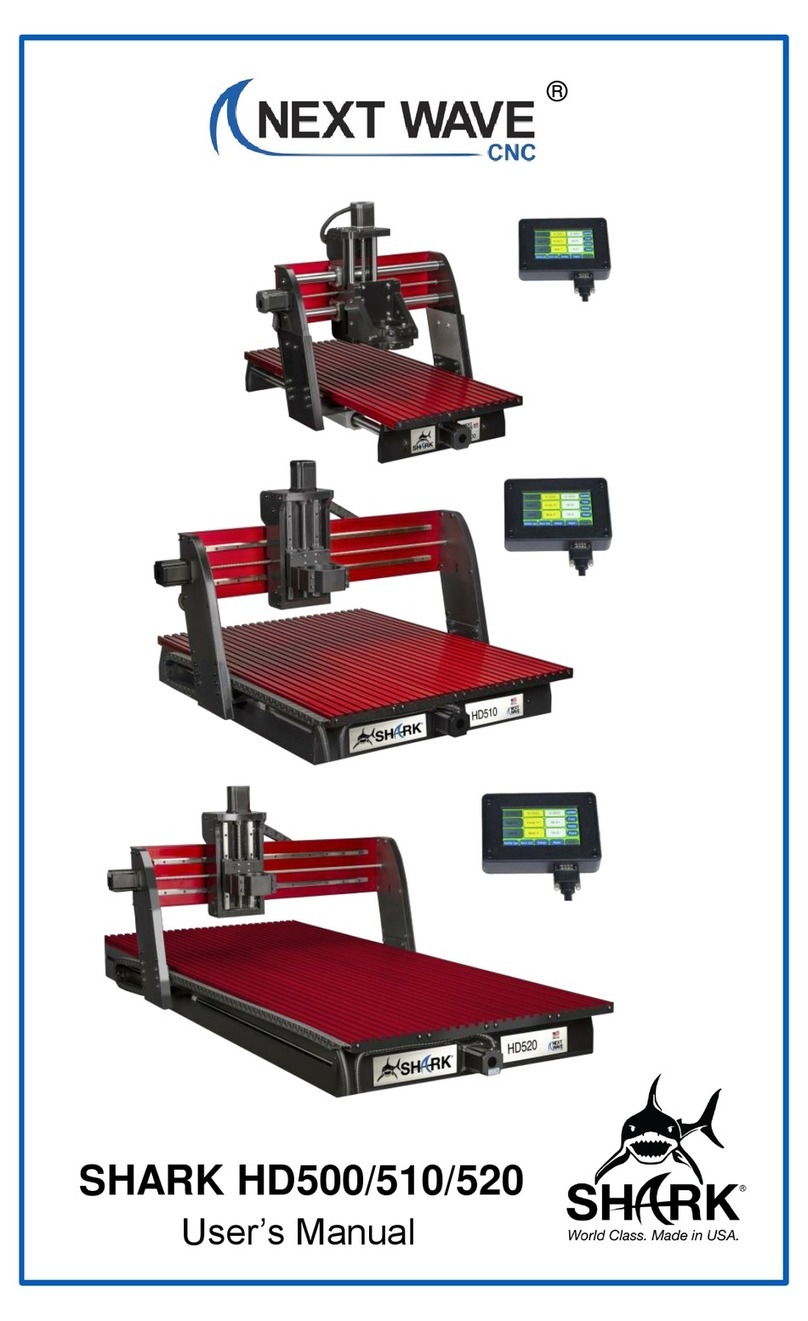
Next Wave CNC SHARK HD500 User manual

HD500/510/520
© 2022 Next Wave CNC - All Rights Reserved

This manual provides important setup and operational information for
your SHARK HD CNC machine. Using your SHARK HD CNC requires
experience with basic computer operation and the technical knowledge
to safely operate power tools.
Thank you for purchasing a SHARK HD CNC from Next
Wave CNC! Your CNC opens up a world of creative
possibilities for your ideas and designs. Following the
step-by-step instructions, your Shark CNC will be up and
running in no time.
Whether you’re new to CNC technology or a seasoned
expert, your SHARK HD CNC provides a lot of flexibility
for programming and operation. Our specially designed
LCD Pendant is an auxiliary touchscreen that provides
hands-on control of many of the functions of the SHARK
CNC right at the machine, without the need for a con-
nection to a personal computer. The Pendant includes a
USB port to transfer files from your PC.
For additional control and programming options using
your PC, we’ve included our Ready2Control software.
Ready2Control allows you to run toolpath files and con-
trol your SHARK HD CNC from the PC. It operates in a
similar way to the LCD Pendant but includes additional
machine control tools. See the Ready2Control User’s
Manual for more information.
Vectric VCarve is a world-wide standard for designing
parts and programming the toolpaths for your SHARK
HD CNC using an intuitive interface. V-Carve includes a
broad set of CNC clip art files and a library of tools for
cutting and shaping the part. Design tutorials and soft-
ware support can be found at Vectric.com.
System Requirements
All SHARK CNCs plug into a standard 110v receptacle
for power. A 15 amp or higher circuit is required.
Ready2Control software requires at minimum, a comput-
er with Microsoft Windows 10 or higher, a 2 Ghz Quad-
Core processor, a minimum of 8Gb RAM, 300 Mb Disk
space (Program), a 1280 x 720 Display monitor, and a
USB-A port.
Vectric VCarve requires a 2 Ghz Multi-Core x86 or x64
processor (Intel or AMD) with Microsoft Windows 10
or higher, a minimum 4Gb RAM, 300 Mb Disk space
(Program) + 7.7GB for optional tutorials and clipart, and
a 1024 x 768 Display monitor.
To Our Customers
Please Read This Manual Carefully
HD500 HD510 HD520
1

Next Wave CNC warrants your new SHARK HD series CNC to be free from defects in
material and workmanship for TWO YEARS from the date of purchase. The warranty
applies only to the original retail purchaser of the SHARK HD series CNC when pur-
chased from an authorized Next Wave CNC distributor. This warranty covers the parts
and labor to correct the defect. It does not cover the cost of shipping the machine and/
or parts to Next Wave CNC for evaluation or repair. This warranty does not apply to
problems arising from normal wear and tear, misuse, abuse, negligence, accidents,
unauthorized repairs, alterations, or lack of maintenance. This warranty is void if the SHARK HD CNC
or any portion of it is modified without the prior written permission from Next Wave CNC, or if the ma-
chine is located or has been used outside of the country where the machine was purchased.
Please contact Next Wave CNC to take advantage of this warranty. If Next Wave CNC determines that
your SHARK HD series CNC is defective in material or workmanship, Next Wave CNC will, at its ex-
pense and upon proof of purchase, send replacement parts to the original retail purchaser necessary
to cure the defect. Next Wave CNC will repair your SHARK HD CNC provided the machine or affected
components are returned to Next Wave CNC, shipping prepaid, with proof of purchase and within the
warranty period.
Next Wave CNC disclaims all other express or implied warranties, including fitness for a particular
purpose. Next Wave CNC shall not be liable for death, injuries to persons or property, or incidental,
consequential, contingent or special damages arising from the use of the SHARK HD CNC .
Ready2Control software Next Wave CNC warrants Ready2Contol and Virtual Zero Unlimited to per-
form as intended and will provide customer support to the original purchaser when purchased from
an authorized retail distributor. Warranty only applies to the current version or the support needed to
update a past version. The cost of the software upgrade (if any) is not covered by the warranty.
Lifetime Technical Support is provided to the original purchaser.
Technical support for the VCarve design software furnished with your Shark CNC is provided by
Vectric. You can find a variety of training videos located at www.vectric.com. If you have questions or
All other trademarks are the property of their respective owners. Information in this manual is sub-
ject to change without notice. The most recent version of this manual can be found at
www.NextWaveCNC.com/downloads-links
www.suite104.com | 248-436-8007 p | cr[email protected] | 18481 West 10 Mile Road, Suite 104, Southeld, MI 48075 | ©2020 All content created by Suite 104 Productions. All Rights Reserved.
Brand Guidelines
SHARK LOGO
7
Next Wave CNC, LLC,
600 W. Boundary St., Perrysburg, Ohio 43551
USA
Main Office Phone (419) 318-4822
info@nextwaveCNC.com
www.suite104.com | 248-436-8007 p | cr[email protected] | 18481 West 10 Mile Road, Suite 104, Southeld, MI 48075 | ©2020 All content created by Suite 104 Productions. All Rights Reserved.
Brand Guidelines
MASTER LOGO
3
®
Contact Us
If you need technical assistance with your
SHARK HD CNC or software, please visit our
Support webpage at:
NextWaveCNC.com/support
or email Customer Support at:
Support@NextWaveCNC.com.
Please include your product model number,
date of purchase, and other pertinent infor-
mation associated with the issue such as .tap
files, VCarve files, screen captures, or photos
of your setup or the problem.
Support Email: support@nextwaveCNC.com
Available: 9 am – 5 pm (ET) Monday-Friday
Serial Number and Software License Information:
For easy reference and record keeping, enter
your SHARK HD and Vectric information at
right. To locate the information, refer to the
pages below.
Controller Box Serial Number
___________________________________
LCD Pendant Serial Number
(page 13)___________________________________
LCD Pendant Unlock Code
(page 13)___________________________________
VCarve License Code
(page 21)___________________________________
Your VCarve User’s Name
(page 22)___________________________________
2 3
Copyright 2022 Next Wave CNC
All Rights Reserved.
SHARK is the registered trademark of
Next Wave CNC.
Ready2Control is copyrighted by
Next Wave CNC.
Virtual Zero Unlimited is patented by
Next Wave CNC.

Machine Overview
Before assembling and using your SHARK CNC, we
strongly recommend viewing the series of assembly
videos with detailed instructions at
https://www.nextwavecnc.com/support.
Determine where in your shop it will be located. As-
sembling your CNC at or near this area will save some
hassle later if the CNC needs moved to its final home.
See the Assembly Overview illustration below to get
familiar with all of the parts of your CNC. You’ll find a va-
riety of videos covering the assembly of your Shark CNC
Router online at https://www.nextwavecnc.com/video.
As you are aware, many components of your CNC are
heavy. To make assembling and moving the CNC easier,
it’s best to have the assistance of a friend or coworker.
Assemble Your CNC Router
Machine Overview..................................6
Assembly Overview................................7
Adding the Gantry .................................. 7
Installing the Cable Carrier .................... 8
Installing the Router Mount....................11
Connecting the Cables ........................ 12
Machine & Pendant Registration ..... 13
Safety Tips ........................................... 14
Stop Your CNC Fast.............................. 15
Basic Pendant Functions
Jog & Speed Settings........................... 16
Zero the X & Y Axes ............................. 16
Move to Origin ...................................... 16
Zero Z Axis - Manually.......................... 17
Zero Z Axis - With Touch Plate ............. 17
Install Vetric VCarve
Software Installation ............................. 18
Opening an Account ............................24
Updating...............................................25
VCarve Workflow ..................................26
1st Build - A Simple Project
Tool Holder...........................................32
2nd Project - Through Cuts
Cutting Board........................................34
3rd Project - Carving
Trivits ....................................................36
Maintenance ........................................39
Resources ............................................40
Upgrade Accessories ........................41
CONTENTS
4 5
Motor moves the router in
the Y-axis (front and back)
Table supports and anchors
workpiece for routing
Cable carrier protects
the cables during CNC
operations
Gantry assembly supports
the carriage and moves
front to back
CNC Base
Motor moves
the router in the
X-axis (left or
right)
A pair of guide rails allow the
carriage to move smoothly
across the gantry
Motor moves the router in
the Z-axis (up or down) Carriage moves the router
in the X-axis and Z-axis
Router mount holds
router securely to
carriage
X Axis
Y Axis
Z Axis

Connect the side cover
with two screws on each end
The slot in the side cover ts over Y-spar
Pilot hole screws
Use the included
bolts and nuts to
attach the gantry
to the Y-spar
Wood blocks (1(/16"- thick)
used as support
for attaching gantry
Side Cover & Gantry Install
Fasten the side covers with screws, just snugging
them up tight.
Support blocks help align the holes in gantry and
Y-spar brackets before fastening it with nuts and bolts.
SIDE COVERS. A Y-spar bracket extends from each side
of the CNC. The Y-spar moves the gantry in the Y-axis. As
shown in the illustration above, slip the slot of the side
covers over the Y-spar brackets. Attach the covers to the
base with four screws, being sure not to overtighten them
(Figure 1).
GANTRY. As mentioned previously, the gantry supports
the router or spindle, moving it in the X and Z directions.
The gantry assembly is heavy, so you’ll want to enlist
some help. Also, positioning support blocks under each
side of the gantry makes the job easier, as illustrated in
Figure 2. Attach the gantry to the Y-spars with six bolts
and lock nuts on each side (Figure 2). Use the top six
holes in the gantry. This is the “low” gantry position. If you
need to cut thick material in the future, you can raise the
gantry using the lower holes for the “high” gantry position.
Screws should be snug
to attach side covers.
Avoid overtightening
12
Gantry supports
the router
for X- & Z-axis
movement
Lift the machine base
by the edges of
the aluminum table
Router/Spindle
mount
Side covers protect
components in the base
Gantry attached to
Y-spar in bed
XZ carriage
6 7
The foundation of your CNC machine is the base. It is
specifically engineered to support the other main compo-
nents. The top of the base also provides a solid, even sur-
face for securing the workpiece before routing or carving.
The gantry is a bridge-like assembly attached to the
base. The gantry supports and moves the router. The en-
tire gantry moves front to back on rails in the base while
the router rides on a carriage that moves left and right.
Your CNC operates on three axes: X, Y, and Z. Standing
at the front of your machine, the X-axis runs left and right.
The Y-axis runs front-to-back. The Z-axis runs vertically
from the table of the CNC. Understanding these basic el-
ements will go a long way toward helping you understand
how to design and make projects with your CNC.
Assembly Overview
Adding the Gantry

Preparing The Cable Carrier
Remove bolt and
nut with a %/32" Allen
wrench and pliers
Lower end
connector
3
Gently pry tabs with
a at blade screwdriver
to avoid damaging chain
Tab hinge side of chain
Tab latch
side of chain
4
Remove the bolt and nut from the lower end connec-
tor of the chain assembly.
Gently pop open tabs and remove the rst three
from the chain assembly.
Upper end connector
Drag chain
houses and
protects
the control
cables
Lower end of cable carrier
bolts to the bottom side
of the Y-spar
The cable carrier is a hollow,
flexible plastic track that resem-
bles a bike chain. Its job is to protect
the cables that connect the controller
to the gantry. As the gantry moves, the
joints in the cable carrier allow it to flex, pre-
venting sharp bends and kinks in the cables
that pass through it. A plastic conduit tube fits
inside the cable carrier to provide additional protec-
tion for the cables.
As shown in Figure 3, start the installation of the cable carrier
by removing the screw for the mounting bracket located at the end
of the chain.
Using a small screwdriver, pry open and remove the three hinged tabs near-
est the mounting bracket with a twisting motion to release the tab from the hinge
point (Figure 4). Pop open the remaining tabs on the cable carrier but do not remove them.
Chain & Cables
Lower mounting
bracket
5
Cable assembly
nestles within drag chain
6
A slight sideways twist is all that is required to
remove the lower mounting bracket.
Fit the cable that extends from the bottom of the
gantry into the cable carrier.
The cable that extends from the bottom of the gantry
contains wiring that connects the CNC controller. This
cable is housed in and protected from damage by the
cable carrier. To make installing the cable into the cable
carrier easier, remove the mounting bracket from the end
of the cable carrier with a slight sideways twist, as shown
in Figure 5.
With all of the tabs open on the cable carrier (Figure 6),
align and insert the cable. Snap the mounting bracket
back in place in preparation for securing the end of the
cable carrier to the Y-spar bracket.
Figure 7 shows you how the mounting bracket fastens to
the Y-spar. Insert the screw from the top through pre-
drilled hole in the horizontal leg of the Y-spar and through
the mounting bracket. Install and tighten the nut securely.
FRONT VIEW
Mounting bracket attaches
to bottom of Y-spar
7
Secure the mounting bracket to the Y-spar with the
screw and nut that was removed in Step 3.
8 9
Installing the
Cable Carrier
Watch the how-to video at:
www.nextwavecnc.com/support

Now that the cable carrier mounting bracket is secured
to the Y-spar, go ahead and snap the open tabs closed
around the cable, as you can see in Figure 8.
Next comes the task of routing the cable carrier inside
the gantry arm and securing it to the CNC base. To do
this, flip the cable carrier over itself so that it creates a
“C” shape, as in Figure 9. The cable carrier should fit
between the base and gantry arm.
To make it easier to secure the cable carrier to the base,
remove the screws from the trim piece at the front of the
base closest to the cable carrier (Figure 10). This allows
you to slide the slot nuts into the T-track on the side of
the CNC table. While holding the loose end of the trim
piece away from the base, slide the slot nuts into the
track on the side of the base. Reattach the front trim
piece, then tighten the bolts on the cable carrier using a
Phillips screwdriver.
Tidy up the cabling by placing the two smaller cable
bundles into the large cable managment tube and secure
each end with a couple zip ties (Figure 11).
Retract trim piece in
order to slide slot nuts
into the base
Tighten bolts
once they're installed
Attaching the Cable Carrier
Secure the cable carrier to the slot in the side of the
base with bolts and slot nuts.
Snap the brackets closed
over the cable to secure the tube
10
Snap the brackets
closed over the cable
to secure the tube
9
8
After tightening the
zip ties, snip the end off
for a clean, nished look
11
Insert the two cable bundles into the large cable
management tube and clamp tight.
The workhorse of the Shark CNC is the
router or spindle. Your CNC comes with
a mount designed to hold a router motor.
A 2hp or 3hp liquid-cooled spindle kit is
available separately from Next Wave. The
spindle provides the same functionality as
a router, but is quieter and designed for
continuous use. The router and spindle
both hold the cutting bits that remove and
shape the material according to the tool-
paths you create in your designs. Whether
you’re mounting a router motor or a spin-
dle motor, the procedure for attaching the
mount to the gantry is the same.
To install the router/spindle, you’ll first
need to attach the mount to the carriage
on the gantry using four bolts, shown in
the illustration at right. Tighten the two
bolts on the closed (right) side of the
mount, but leave the pair of bolts on the
slotted (left) side loose for now.
Now insert the router into the mount. Posi-
tion the collet about 33⁄44” above the table.
This position ensures most router bits will
reach the table. You can adjust this height
as needed for long bits or thick projects.
Tighten the remaining bolts to ensure the
router doesn’t move in the mount. If you
need to adjust the cutting height of the
router later on, simply loosen the two bolts
on the slotted side and adjust the position
of the router, then tighten the bolts. Zip-tie
the power cord to the rear cable carrier to
keep it out of the work area. Make sure to
leave enough slack at the top to allow the
router to move up and down freely.
DO NOT PLUG IN AND TURN ON THE POWER UNTIL AFTER ALL
OF THE MOTOR CONNECTIONS HAVE BEEN MADE. DO NOT
EVER ATTACH OR DETACH THE MOTOR CABLES WHEN THE
CONTROL BOX IS POWERED UP, AS THIS WILL DAMAGE THE
ELECTRONICS AND IS NOT COVERED BY THE WARRANTY!
IMPORTANT: READ CAREFULLY
Position
power cord away
from work area
Slot
To install the router/spindle mount on the carriage, fully tighten the bolts
on the right side, then insert the router/spindle and tighten the bolts on
the slotted side.
Installing the Router
10 11
Snap all of the remaining tabs closed to secure the
cable.
Route the cable carrier to the inside of the gantry arm
to position it for nal attachment to the CNC base.

Connecting the Cables
As you have discovered by now, and as is shown
in the drawing below, there are several electrical
connections that need to be made before you can
power up your Shark CNC. The control box acts as
an interface for all of the connections.
Begin by attaching the three motor cables to the
control box. Each cable controls a separate motor.
The ends of the cords are labeled accordingly.
Insert the end of the Z, Y, and X cables into their
respective port on the rear of the control box.
Secure the cables by tightening the two screws on
each plug finger tight. Plug the white RCA cables
into the round RCA jacks. These cables control the
“homing” function of the CNC, which you’ll learn
about later.
Your router’s power plugs into the back of the
control box. The electronics in the control box
will power up the router and turn it off as needed.
Finish by plugging in the primary AC power cable
for the control box into the female connector on the
rear of the control box.
NOTE: If you have the spindle kit, follow the con-
nection instructions that come with your spindle.
The Pendent provides an easy way to interface with
the Shark CNC for controlling many of its functions.
Plug one end of the Pendant cable into the port on
the Pendant. Connect the other end to the port on
the front of the control box.
It’s best to use a power strip with surge protection
for your CNC. This protects it from power spikes
that might interrupt the operation of the CNC. If you
need to use an extension cord, we recommend a
heavy-duty 12/3 cord. Plug the control box into the
power strip. Now you can power up the control box
with the switch on the rear of the box. To ensure
that power is flowing to the machine, double check
that the emergency stop is turned to the left and
the button is popped out (pushing it turns it off).
You can power down the CNC using either of these
switches.
Y Control Motor
Control Box
LCD Pendant
Homing
Plugs
AC Power
X Control
Motor
Control motor
cables are labeled
for easy hook up
Router
Plug In
Emergency
Stop
XYZ
Z Control
Motor
Wiring Schematic
Registering the Pendant
Click
Here
Unlock the Pendant by entering the access code
you received upon registration.
After successfully unlocking the Pendant, you’re
ready to control your SHARK HD CNC.
12 13
Pendant Registration
Before continuing the setup of your SHARK HD CNC,
register your machine online by navigating your web
browser to NextWaveCNC.com. Click on the PRODUCT
REGISTRATION tab at the top of the screen (see above).
Once you complete the registration the unlock code will
display on your computer screen. (An account confirma-
tion will also be sent to you email.) Use the number keys
on the Pendant to enter your Unlock (Access) Code.
For complete and detailed instructions on using the
Control Pendant, refer to the Pendant User’s manual.

1. Read, understand, and follow the safety
and operating instructions before using your
SHARK CNC.
2. Take time to fully understand how to safely
operate your SHARK CNC.
3. Setup your SHARK CNC following the in-
structions in this manual.
4. Always wear appropriate eye and hearing
protection when operating your SHARK CNC
and accessories.
5. Machine only non-ferrous metals with your
SHARK CNC.
6. Never attempt to adjust the workpiece or
move the SHARK while it is running.
7. If needed, use the Cancel or Pause buttons to
Stop or Pause your SHARK CNC during an oper-
ation.
8. Never leave your SHARK CNC unattended
while it is running.
9. While operating your SHARK CNC, keep a
multi-purpose, dry-chemical fire extinguisher
nearby. It must be rated for both A & C fires.
10. For added safety and convenience,
connect your SHARK CNC to a 110-115V
surge-protected power strip with an on/off
switch. This provides an additional way to turn
off the machine in case of an emergency.
11. Follow all Safety instructions provided with
your SHARK CNC and accessories.
12. Follow all accepted and recommended
safety precautions and practices for woodwork-
ing and machining.
Our 12 Golden Rules for Safety
4 Ways to Shut It Off
Stop Your CNC Router Fast!
Every CNC user experiences times when the machine
seems to have a mind of its own. This can be caused
by errant tool paths in the design file, power surges,
broken tools, or any number of other reasons.
1. First, you can use the Pendant to stop the machine.
Simply press the red STOP button on the Pendant
screen. This stops the CNC’s movement and turns off
the router/spindle.
2. The second option for quickly stopping the CNC
operation is to press the large, red Emergency switch
on the front of the control panel.
3. You can also use the power switch on the rear of
the control box to shut down the system.
4. If you have the control box plugged into a switched
power strip, you can also power down the machine in
an emergency by turning of the power strip.
IMPORTANT NOTE: If you stop your CNC using any
of these methods, you will need to restart the cutting
from the beginning of the file, since the cutting prog-
ress and machine positions are lost during an emer-
gency shut-down.
Once you are familiar with the locations of these
switches, you’ll be ready to use them if and when you
need them in the middle of a routing project.
Methods 2, 3, or 4 also work to shut off your machine
at the end of the day.
2
3
4
1
14 15

Make It Move
Basic Pendant Functions
The Pendant has many great functions to control the
SHARK HD CNC. But you only need to learn a few basic
operations to get started.
JOG AND SPEED SETTINGS. Let’s start with learning
how to move (jog) the router. Jogging the router allows
you to move it out of the way or to another location. This
comes in handy for locating or removing clamps on the
workpiece, changing router bits, or setting up start points
for the router to run a routine.
First, look at the main screen (Figure 1) and identify the
jog keys. They are quick to identify when standing in front
of your CNC and are intuitive to use. You can jog the
router right or left in the X-axis, toward you or away from
you (Y-axis), or up and down in the Z-axis.You control
the speed of the jog from fast to slow by using the speed
key on the right side of the Pendant screen (red arrow).
Pressing this key repeatedly cycles between Fast, Medi-
um, and Slow jog speeds.
Take some time to experiment with moving the spin-
dle around. Jog the router to get a feel for the different
speeds. Take special note of the position readouts at the
top of the Pendant screen. Try to stay within the limits
of the machine. If the router travels and bumps against
the limits, you may here a “grinding” noise. Don’t be
concerned—the noise is the sound of the internal motor
magnets electronically skipping over each other. This
does not cause any damage, but it’s good practice to
avoid hitting the travel limits of your machine.
ZERO X- & Y-AXES. Another function of the Pendant is
the “Zero XY” function, as shown in Figure 2. This sets
the current position of the router as a zero, or origin point
for the X- and Y-axes.
Origin points are typically used as a starting point to
run a cutting routine. Often the center of a workpiece or
the lower left corner are used as a starting point for the
X- and Y- axes. The Z-axis origin is usually set from the
top of the workpiece. We’ll cover setting the Z-axis on the
next page. For now, practice setting up for a cut by exper-
imenting with moving the spindle to a number of locations
and zeroing the X- and Y-axes.
MOVE TO THE ORIGIN. Another useful Pendant func-
tion for moving the router is the “MV 0,0” key ( Figure 3).
Pressing this key with a short press or single tap auto-
matically moves the router to the X- and Y-origin point you
have previously set. Set a new origin point and give it a
try. Using a long press/double tap moves the spindle to
the original X-, Y-, and Z position.
Changing the location of the router is easy with the
easy-to-use Pendant interface.
The Pendant makes it easy to set a new X, Y, and Z
origin for the router’s location.
Use the MV 0,0 button to move the router back to the
previously set origin.
1
2
3
Manual Setup
Most of all, have fun! Experiment with the basic Pendant
functions to get familiar with how your SHARK HD CNC
moves and sounds.
Learning to zero the X-, Y-, and Z-axes is an important skill
for accurate work. You can zero the Z-axis manually or auto-
matically with the help of the Next Wave CNC Touch Plate,
available as an add-on accessory (see figure 6 below).
ZERO THE Z-AXIS MANUALLY. Setting the Z-axis zero
point manually is an easy process. First, install the router bit
you’ll use for the project into the collet of the router. Begin by
moving it to the marked center of your workpiece using the
jog functions shown on the opposite page. Change the jog
speed on the Pendant to “Slow.” Carefully move the bit over
the center mark on the workpiece by using the X- and Y- jog
keys. With the bit centered over the workpiece, press the
“Zero XY” key to zero the X- and Y- axes.
To zero the Z-axis, lower the bit to within about ½” of the top
of the workpiece and set the jog speed to slow. Slide a piece
of paper underneath the bit and move it back and forth as
you tap the “Dn Z” key to gradually lower the bit. When the bit
starts to “grab” the paper, stop. Press the “Zero Z” key again,
then raise the router bit approximately ½”. At this point, all
three axes are calibrated.
USING THE CNC OPTIONAL TOUCH PLATE. Using the
CNC Zero Touch Plate accessory is a fast and accurate way
to zero the Z-axis, as shown in figure 6. Begin by plugging
in the lead into the Pendant. Position the Touch Plate under
the router bit. Attach the magnet on the end of the lead to the
collet or bit.
Press the “Plate” key on the main screen of the Pendant and
follow the steps listed. When the router bit comes into contact
with the Touch Plate, this completes an electrical connection
to indicate the zero position of the Z-axis. The bit automati-
cally retracts to a safe height.
4
Zero the X- and Y- axes rst by jogging the bit until
it’s positioned over the center of the workpiece.
5
Gradually lower the bit until it just starts to touch
a piece of paper placed on the workpiece.
Optional Zero Touch Plate
6
The CNC Touch Plate has a single lead on one
end of the cord. Plug this into the side of the
Pendant. Position the CNC Touch Plate under the
router bit and attach the magnet to the collet nut
or side of the bit.
16 17

Installing VCarve Software
Using a CNC router is unlike any other powered wood-
working tool—you can’t just power it on and put to use
right away. Making projects with the CNC is a little more
involved. The CNC must be programmed with instructions
that define the router bits, toolpaths, and cutting speed to
be used for your project.
For your own creations using the SHARK CNC, the first
thing to do is design your project. Then you define the
tools and toolpaths that will be used by the CNC to cut
the workpieces
VECTRIC VCARVE. Your SHARK CNC comes with a
license for Vectric VCarve design software. This powerful
and user-friendly software unleashes your creativity. For
system requirements, visit:
vectric.com/support/system-requirements
There are a number of steps involved in installing, reg-
istering, and configuring VCarve so be patient, go slow,
and remember that you only have to do this once. Step-
by-step instructions start on the next page.
NOTE: During the installation process,you’re required
to register VCarve twice. The first time, you’ll use the
Username and License Code printed inside the box lid.
Then you’ll need to register again using your personal
Username, and a new License Code that is emailed to
you from Vectric after the first registration. This process is
shown in the steps that follow.
Vectric offers excellent instructional tutorials and custom-
er help at Vectric.com. Take advantage of this valuable
resource.
Important –Please Read
Installing and registering the VCarve software requires several steps. The
instructions in this section show the typical installation and registration
process. Following these steps will result in a successful
installation. However, variations in security settings, virus protection and
operating systems can prevent a smooth installation. The process may also
vary due to any changes to the installation process occurring after this manual
was printed. If you experience problems installing VCarve on your computer,
first try repeating the process. If the problem persists, email Register@Vectric.
com for assistance. VCarve is supplied and supported by Vectric, LT D . They
are best suited to help you with software installation problems. For design sup-
port and training with VCarve, visit www.vectric.com and click on the Support
Tab for information and video tutorials. You can also email your VCarve ques-
Software Installation Process
STEP 1.
Insert the VCarve USB-A drive into a USB
port on your computer.
STEP 2.
Using File Explorer, navigate to the USB
drive and double-click on the le setup.exe.
STEP 3.
Click on Design & Toolpath Software to
install Vectric Vcarve on your computer.
STEP 4.
Click on INSTALL SOFTWARE to begin the
installation.
STEP 5.
A box will pop up (appearance may vary)
asking if you want to allow this software to make
changes on your computer. Click OK.
STEP 6.
Choose your preferred language from the
pull-down list and select OK.
18 19

Software Installation Process continued
STEP 9.
Ensure that Shell Extension is selected then
click Next.
STEP 10.
Using the default location on your computer
is recommended, but you can use the Browse button
to select a different location. Click Next to continue.
STEP 11.
Accept the default Start Menu Folder by
clicking on Install.
STEP 12.
Wait until the installation process is com-
plete before clicking on Next.
STEP 7.
Follow the instructions on this pop-up and
select Next.
STEP 8.
Read through the license agreement and
select I Agree to continue the software installation.
Software Installation Process continued
STEP 13.
With the box labeled Run VCarve Desktop
checked, press Finish to start VCarve.
STEP 14.
To begin registering the software, choose
Ofine then click Next.
STEP 15.
.You’ll be entering your license information
from the box lid, so select Manual and press Next.
STEP 16.
Choose Enter User Name & License Code,
then enter the Registered User Name and License
Code from inside the box lid.
STEP 17.
Click Finish to proceed to the Personal
Registration screen.
STEP 18.
You’ve registered the Next Wave version
of the software, now you need to enter your personal
registration information by clicking Register Now.
20 21

Software Installation Process continued
STEP 19.
Select the option for personal use under
Registration Type and enter your Contact Details.
Click Submit Registration Request.
STEP 20.
If you have successfully registered the
software, you will see this screen.
STEP 21.
You will receive an email from Vectric that
contains the registration information you need to
license the software under your personal user name.
STEP 22.
In VCarve, you may see a pop-up dialog
box asking for your license code. You can also select
Enter License Code from the Help drop-down menu.
STEP 23.
Since you’ll be entering the license infor-
mation from the email you received from Vectric,
select Ofine then click Next.
STEP 24.
You’ll be able to copy and paste your
license code from the email, so choose Manual and
click on Next.
Software Installation Process continued
STEP 25.
Choose the option to Enter License Data
then cut and paste the license information from the
email you received. Click Next.
STEP 26.
The license information shows your user-
name. Check the box Restart Now then click Finish to
restart VCarve.
STEP 27.
If you click Finish in Step 26 without check-
ing the box Restart Now, you can simply choose Exit
from the File pull-down menu to exit VCarve.
STEP 28.
After restarting VCarve you should see
your username at the top of the screen and under
Licensed To in the opening window.
22 23

Opening a Vectric Account
Updating Vectric VCarve
STEP 1.
At Vectric.com, click Login to V&Co to create
a portal account for access to special content down-
loads, software updates, and technical support.
STEP 2.
If you have an existing Vectric account, log
in here (See Step 3).
STEP 3.
If you have an account at Vectric.com, enter
your username and password. If you’re a new user,
scroll down and select Click here to sign up now!
STEP 4.
For setting up a new Vectric account, enter
your contact information and password, accept the
Terms & Conditions, and click Sign Up.
STEP 1.
If software updates are available, an update
notice appears in the upper right corner of the screen
when you open VCarve. Click it to install the update.
STEP 2.
Your system must be connected to the inter-
net to download updates. When you click Next, the
system checks for any available updates for VCarve.
Updating Vectric VCarve continued
STEP 3.
If there is an update for the software that
checks for and delivers the VCarve updates, it will be
installed rst. Click OK to continue.
STEP 4.
Any updates for VCarve will be displayed.
Click Next to install the update.
STEP 5.
In order to properly install the update,
VCarve must be shut down. Click Retry to continue
installing the software update.
STEP 6.
This informational dialog will appear. Simply
click Start to continue installing the software update.
STEP 7.
After the software upgrade is installed, press
Finish to continue using VCarve.
STEP 8.
If you’re interested in all of the features or
software bugs that were addressed with the update,
click on See Release Notes. Otherwise, click Later.
24 25

2
Now it’s time to learn how to create your own projects
and the .tap files needed to cut them using the power-
ful tools in VCarve. Let’s take a look at how the process
works.
To create a new design in VCarve, select Create a new
file from Startup Tasks (Figure 1). A Job Setup dialog box
allows you to set up parameters for the project (Figure 2).
Let’s begin by entering the width, length and thickness of
the project. Be sure to think about how the workpiece will
be secured to your machine, as you may need to make
the material larger to accommodate hold downs.
The Z Zero and XY Datum Points are important referenc-
es to orient the CNC machine correctly to the workpiece.
For this project example the Z Zero is on top of the ma-
terials surface and the XY Datum Point is in the center of
the project. This is how the example projects listed later in
the manual are set up.
Click OK to save and exit the Job Setup window.
1
A Productive VCarve Workow
Use the toolpath tools to assign router bits to the lines
in your drawing. This process begins by highlighting the
lines on the drawing which will become the toolpath
(Figure 4 at right), choosing the type of cut (profile,
pocket, or V-carve for example, (Figure 5 next page) and
selecting the router bit that will be assigned to the cut.
Learning to setup the various parameters for router bits is
the other big challenge in learning to use a CNC router.
VCarve has a Tool Database with many common router
bits listed and default settings for each (Figure 6 next
page), however every project is different and may require
you to change the parameters.
Understanding how to use drawing tools is one of the big-
gest parts of the CNC learning curve, but there are many
resources available to help you master VCarve. You can
find a complete listing of resources at Vectric.com and
nextwavecnc.com/Webinars.
Once you have a basic understanding of the drawing tool
groups, dive in and start working with them. If you need a
place to start as you learn, one way is to use the clip art
that comes with VCarve, or to import a drawing that you
can trace over. Add a frame and some text and you’ve got
a project (Figure 3 below).
Drawing Tools
3
Toolpaths
4
26 27

All bits - Pass Depth 0.05 to 0.125 in.
All bits - Feed Rate 50-120 ipm
All bits - Plunge Rate 50-80 ipm
Straight bit Step over 10% - 40%
V-bits - Final pass 2%
V-bit - Clearance pass 20%
Ballnose bit - 3D nishing pass 7-11%
The settings listed below work well as a starting point
for most bits and materials. For some bits and materials,
you may want to use more or less aggressive settings
than shown below. Practice on spare material to fine tune
these numbers to ones that work best for you.
5
6
7
8
Check the toolpaths you wish to save and select the
Post-Processor that matches your machine. For your
Shark CNC router select the Next Wave CNC (*.tap)
post processor. The post processor converts the VCarve
drawing and toolpath selections into a file that tells your
CNC machine where to move. The code file has a .tap
extension and is commonly referred to as a .tap, G-code
or cutting file. Finish by pressing the Save Toolpath key
and saving the file to a thumb drive (Figure 8 below).
Preview & Save Toolpaths to Thumbdrive
The preview window in VCarve is an important tool in the
process to make sure that the toolpaths you have creat-
ed are cutting where you want them to cut. The window
displays the completed project in 3D and allows you to ro-
tate and inspect it (Figure 7 below). If something doesn’t
look right in the Preview Toolpath window it means that
something is probably wrong with one or more of your
toolpaths. To correct the problem you may need to adjust
the settings in the toolpath or make changes to your
drawing in the 2D window.
28 29

CNC Setup
Zero the X- and Y- axes rst by jogging the bit until
it’s positioned over the center of the workpiece.
Gradually lower the bit until it just starts to touch
a piece of paper placed on the workpiece.
After inserting the ash drive into the Pendant,
press the “USB” button to select the project le.
11
From the list of available projects, select your chose
.tap le to proceed.
12
910
Setting Up Your HD Machine for Cutting
Mark the XY Datum position on your material and secure
it to the machine bed of your router. In our example the
XY Datum point is specified as the center of the material,
but you can choose any of the four corners as well.
After installing your preferred router bit for the first cut,
use the X- and Y- jog keys in the jog function of the
Pendant to move the router close to the XY Datum mark.
Change the jog speed to “slow” and position the router bit
directly over the mark (Figure 9 below). Press the “Zero
XY” key to zero the X- and Y- axes.
To zero the Z-axis, lower the bit to within ½” of the top
of the workpiece and set the jog speed to slow. Slide a
piece of paper underneath the bit and move it back and
forth as you tap the “Dn Z” key to gradually lower the bit.
When the bit “grabs” the paper, stop. Press the “Zero Z”
key and raise the router bit approximately ½”. Now all
three axes are calibrated.
Now insert the thumbdrive into the Pendant and press
the USB key to open the file selection menu. Press on the
project .tap file you want to cut (Figures 11 & 12 below).
Preview the settings to make sure you’ve selected the
right .tap file, and that the settings match how you have
prepared the VCave file and your CNC machine (Figure
13). If everything checks out, press Next.
Review the safety check lists from page 33, 35, or 37,
turn on your router and press Start. Your Shark CNC rout-
er will begin cutting the project (Figure 14). Once the first
toolpath is cut, change router bits and re-zero the Z-axis.
Now return to the Pendant main screen and repeat steps
12, 13, and 14.
When all of the .tap files have been run, remove your
project, sand and finish.
Verify all of the set-up information for this job, review
the safety checklist, then press “Next”.
13
To begin the CNC operation, simply press “Start”.
14
Review, Then Cut
Finishing the Job
30 31
If you experience issues with your VCarve software please
contact Vectric for help at [email protected]

Project 1: Tool Holder
The first project you’ll make on your
CNC is a practical one: a router
bit and wrench organizer, shown
at right. This project demonstrates
pocket cuts, which don’t cut all the
way through the material.
The first thing you’ll need to do is
download the project cutting file
by navigating your web browser to
NextWaveCNC.com/cncprojectplans.
Copy the .tap file for the Tool Holder
HD project to a USB flash drive. The
.tap file contains the G-code that tells
your machine how to move.
For this project you will need a piece
of solid wood, plywood, or MDF
(medium-density fiberboard) 8½” x
11” x ¾” thick. Mark the center of the workpiece to use
as a reference for zeroing the X-, Y-, and Z-axes. Using
the hold-down clamps that came with your CNC router,
securely clamp the workpiece to the table of the CNC, as
shown in Figure 1 below.
Now you’ll install a router bit and zero the X-,Y- and
Z-axes, as shown on pages 16 and 17 of this manual.
Install a ¼” straight router bit in the collet of your router or
spindle and set the speed to approximately 17,500 RPM
(Spindles equipped with a spindle interface cable will
automatically set the speed). Use the Pendant to zero the
X- and Y- axes and then zero the Z-axis.
To load the project .tap file that feeds instructions to the
CNC, insert the thumb drive into the Pendant. Press the
“USB” button (Figure 1 next page) to open the file selec-
tion window. Select the Tool Holder HD.tap file (Figure 4
next page).
The next screen that pops up (Figure 3) displays set-up
information about the file. Once you have reviewed the
setup press “Next.”
Before going any further, now is a good time to review a
safety checklist. You should go through this checklist for
every project you make on your CNC.
Workpiece Set-Up & Routing
Mark a center point on the workpiece before securely
clamping it to the CNC table with hold-down clamps.
Zero the X-, Y-, and Z-axes before proceeding.
The project le contains the instructions for the CNC to
make all of the pocket cuts in the workpiece.
32
12
SIDE RAILS. grammatica, li pronunciation e li plu
commun vocabules. Omnicos directe al desirabilita;
Verify, Then Create!
After inserting the ash drive into the Pendant,
press the “USB” button to select the project le.
Is the workpiece securely clamped to the table?
Have you zeroed the X- and Y- axes to the center of
the workpiece?
Have you zeroed the Z-axis to the top surface of the
workpiece?
Is the router or spindle set to approximately 17,500
RPM?
Have you reviewed the emergency stop procedures?
Are you wearing hearing and eye protection?
Press “Start” and watch your CNC router create your first
project, as shown in the lower right drawing, previous
page.
NOTE: You can press the pause button on the Pendant
screen to stop the movement of the router if you need
to make a minor adjustment. You must also turn off the
router or spindle to avoid injury. Once you’ve made all of
the adjustments needed, restart the router or spindle and
press “Resume.”
Once the project is routed, power off the router and
remove the workpiece. All that’s left is to sand and apply
a finish to the organizer. Now you’ve got a convenient
storage place for the router collets, wrenches, and bits.
Verify all of the set-up information for this job,
review the safety checklist, then press “Next”.
33
3
5
From the list of available projects, choose the
Tool Holder HD.tap le to procede.
4
To begin the CNC operation, simply press “Start”.
6

Review your safety checklist:
Is the workpiece securely clamped to the table?
Have you zeroed the X- and Y- axes to the center of
the workpiece?
Have you zeroed the Z-axis to the top surface of the
workpiece?
Is the router or spindle set to approximately
17,500 RPM?
Have you reviewed the emergency stop
procedures?
Are you wearing hearing and eye protection?
Press “Start” and watch your CNC router cut the profile of
the cutting board, as illustrated in the lower right drawing,
previous page. Note the tabs created during the routing
process that hold the cutting board in place.
NOTE: You can press the pause button on the Pendant
screen to stop the movement of the router if you need
to make a minor adjustment. You must also turn off the
router or spindle to avoid injury. Once you’ve made all of
the adjustments needed, restart the router or spindle and
press “Resume.”
When the CNC stops, power down the router before
removing the workpiece and waste board. Use a chisel
or small hand saw to cut through the tabs to separate
the cutting board. Clean up the remnants of the tabs
with rasps and sandpaper. Sand the entire cutting board
smooth before applying a food-safe finish.
As a word of caution, you can damage your cutting board
by placing it in the dishwasher. Instead, simply wipe it
clean with a damp cloth and mild detergent between uses.
35
SIDE RAILS. grammatica, li pronunciation e li plu
commun vocabules. Omnicos directe al desirabilita;
Verify, Then Create!
After inserting the ash drive into the Pendant,
press the “USB” button to select the project le.
Verify all of the setup information for this job,
review the safety checklist, then press “Next”.
3
5
From the list of available projects, choose the
Cutting Board.tap le to proceed.
4
To begin the CNC operation, simply press “Start”.
6
Project 2: Cutting Board
This project will find a practical use in your
kitchen, as shown at right. The cutting
board demonstrates a “through profile”
cut where the finished piece is separated
from the parent material. Think of it like a
bandsaw.
You may be wondering how the cutting
board can remain secure on the table if the
router cuts the complete profile around it.
There’s a trick CNC users employ called
tabs that keep the project connected to the
rest of the board during cutting. .
Tabs are small, connecting pieces of mate-
rial that span the kerf left by the router bit.
To create these tabs, the CNC doesn’t cut
all the way through the thickness of the material in certain
areas. After the the job is done, you can cut through the
tabs with a saw or chisel, then sand the profile smooth.
Begin by going downloading the Cutting Board HD.tap file
from NextWaveCNC.com/CNCprojectplan. Copy the file
onto a USB flash drive.
Attractive, tight-grained hardwoods are best for a cutting
board. Prepare a blank 9” x 14” x ¾” - thick. Now is a
good time to mark the center point of the workpiece for
zeroing out the axes.
Since the CNC cuts through the entire thickness of the
blank, you need to place a waste board underneath the
blank. This prevents the router bit from cutting into the
CNC table. Use a waste board that’s at least a 11⁄44” thick
and the same size or larger than the cutting board blank.
Place the waste board under the workpiece blank and
clamp them to the CNC table using hold-down clamps.
Install a ¼” straight bit in the collet of your router or spin-
dle and set the speed to 17,500 RPM. Zero the X-, Y-, and
Z-axes.
Insert the thumb drive into the Pendant to load the cutting
file. Press the “USB” button (Figure 1) on the main screen
to open the file selection window. Locate and select the
Cutting Board HD.tap file, as shown in Figure 4 at right.
As shown in Figure 5, set-up information for the job pops
up for your review and verification. If everything looks
okay, press “Next.”
Workpiece Set -Up
Mark a center point on the workpiece before securely
clamping it and the waste board to the CNC table with
hold-down clamps. Zero the X-, Y-, and Z-axes.
Wasteboard
Watch the router cut around the prole of the cutting
board while leaving tabs to keep it secure on the
CNC table.
34
12

Once you’ve zeroed the X-, Y-, and Z-axes, insert the
thumb drive into the Pendant. To select the file for pro-
cessing, press the “USB” key (Figure 3) to open the file
selection window. Select the file Trivet Vcarve HD.tap as
shown in Figure 4.
Figure 5 represents the set-up information about the file
that you should review and verify. If everything checks
out, press the “Next” button.
Review your safety checklist:
Is the workpiece securely clamped to the table?
Have you zeroed the X- and Y- axes to the center of
the workpiece?
Have you zeroed the Z-axis to the top surface of the
workpiece?
Is the router or spindle set to approximately
17,500 RPM?
Have you reviewed the emergency stop
procedures?
Are you wearing hearing and eye protection?
Press “Start” and watch your CNC router carve an intri-
cate pattern on the workpiece.
NOTE: You can press the pause button on the Pendant
screen to stop the movement of the router if you need
to make a minor adjustment. You must also turn off the
router or spindle to avoid injury. Once you’ve made all of
the adjustments needed, restart the router or spindle and
press “Resume.”
37
SIDE RAILS. grammatica, li pronunciation e li plu
commun vocabules. Omnicos directe al desirabilita;
Verify, Then Create!
After inserting the ash drive into the Pendant,
press the “USB” button to select the project le.
Verify all of the setup information for this job,
review the safety checklist, then press “Next”.
3
5
From the list of available projects, choose the
Trivet HD V-Carve.tap le to proceed.
4
To begin the CNC operation, simply press “Start”.
6
Project 3: Carved Trivet
This project, a trivet, features a technique
that you may not be familiar with: V-carv-
ing. This versatile cutting method uses a
V-shaped router bit to generate appealing
designs by using cuts of varied widths.
You can see these intricate cuts in the
photo at right.
During operation, the V-bit gradually rises
and lowers as the Z-axis moves in sync
with the X- and Y-axes. This creates a
tapered look unique to V-carving. With
this technique, you can create beautiful
lettering and amazing patterns.
The trivet is made with two different
cutting techniques. First, you’ll create
the decorative pattern and lettering using
a V-carving cut and a 90 degree V-bit.
The second operation is a profile cut that
creates the round shape of the trivet in
the same way that you made the cutting board, using a
¼” straight bit, a waste board, and utilizing tabs to keep
the project from moving. When different router bits or
types of cuts are used for a project, a separate cutting file
is required for each.
Get started by downloading the project cutting files from
Next-Wave.com: Trivet Vcarve HD.tap and Trivet Profile
HD.tap. Copy the files onto a USB flash drive.
For this project, you will need a piece of solid wood that
measures 12” x 12” x ¾” thick. Hardwoods like maple
or cherry work best. You will also need a waste board to
place under the trivet material. Mark the center of the
blank, then clamp the blank with the waste board under-
neath to the CNC table using the hold-down clamps, as
shown in Figure 1. Install a 90° V-bit bit in the router collet
and set the speed to 17,500 RPM.
Workpiece Set -Up
Mark a center point on the workpiece before securely
clamping it to the CNC table with hold-down clamps.
Zero the X-, Y-, and Z-axes.
The V-bit makes unique cuts that create an eye-catch-
ing pattern in three dimensions.
36
12
Other manuals for SHARK HD500
1
This manual suits for next models
2
Table of contents
Other Next Wave CNC Control System manuals
