Distech Controls EC-BOS-8 User manual

1
EC-BOS-8 Quick Start Guide
EC-BOS-8 with one option module
October 9, 2017
QUICK START GUIDE
3DIN Mount (2)
5. Install module
6. Install end-clips
1Insert Card
13
2
1 Access Shutter
2 Card Carrier
3 MicroSD Card
4Communications
WLAN
1 RS485
2 WLAN
3Ethernet
4 Ground & power
2DIN Mount (1)
1 Pull down clip
2Tilt and hook
3 Push down & in
4 Push up clip
5RS485 Example
IO-R-16
IO-R-16
IO-R-16
IO-R-16
IO-R-16
1 Port A (COM1)
2 Port B (COM2)
3 See note

2
7LED
123
45 6 78
1 WLAN (Green)
2 RS485 “A” (COM1)
3 RS485 “B” (COM2)
4 STAT (Green)
5 BEAT (Yellow)
6 Ethernet (LAN2)
7 Ethernet (LAN1)
8 Backup (Green)
6Ground & Power
50/60Hz
1Ground
2Power
2.1 AC and transformer
2.2 DC
2.3 AC adapter
8Ports & Switches
BACKUP
3
BACKUP
5
4
SHT/DWN
DEBG
2
1PROG
1 USB 2.0
2 Micro-A USB
3 USB backup/recovery
4Shutdown
5 “Job in progress” LED
iOption (1)
12
2.44 (62)
0.34 in.
(8.6 mm)
0.165 in.
Dia.
(4.2 mm)
2.11 (53.5)
6.71 in. (170.5 mm)
3.31 in.
(84 mm) 3.31 in.
(84 mm)
4.33 in.
(110 mm)
6.38 in. (162 mm)
7.05 in. (179 mm)
1 Controller
2Module
iOption (2)
2.13 in.
(54 mm)
2.13 in.
(54 mm)
6.71 in.
(170.5 mm)
3
iEC-Net Access Enclosure Example
–+
s
+
s
120 VAC
–+
+ –
Remote
Reader
Remote
Reader
Remote
IO
15VDC
24VDC
NPB-PWR
VAC
VDC
Gnd
AC
AC
L
N
G
+ –
1 Enclosure
2 Install <=4 modules
3 Enclosure Door Alarm
4 AC/Battery Monitor
1
2
3
4

3
EN
NOTE: A maximum of four (4) total option modules are
supported. Separate limits may exist in the controller’s
license, which can further limit options.
Description
EC-BOS-8
DIN-mount, 24Vac/dc (50/60Hz) powered, area control-
ler. See the product data sheet for complete specica-
tions. See the controller’s Mounting and Wiring Guide
for complete hardware installation details.
WPM-8000
Wall-mount, Class 2 universal AC power adapter supply-
ing 24Vdc.
NOTE: Intended for oce demo use. Excluded from
agency testing.
Included in this package
is package includes the following items:
• EC-BOS-8
• MicroSD card in plastic case. See “Preparation”.
• Coax-mount, dual 2.4/5.8GHz antenna for a wireless
local area network (WLAN). Antenna impedance =
50 ohms. Antenna Max Gain = 2.4GHz Band: 2.5dBi,
5GHz Band : 4.6dBi
• Two 3-position RS485 connector plugs, one
2-position power connector, and a grounding wire.
• is EC-BOS-8 Quick Start Guide.
Material & Tools Required
• One of the following:
– UL listed, Class 2, 24Vac transformer, rated at min-
imum of 24Va. A dedicated transformer is required
(cannot power additional equipment), or
– User supplied UL Listed Class 2 or LPS AC power
adapter: 24Vdc, capable of supplying at least 1A
(24W). Optional barrel connector plug (9.5mm L x
5.5mm OD x 2.1mm ID) or
– WPM-8000 wall-mount AC power adapter with
barrel connector plug.
• DIN rail, type NS35/7.5 (35mm x 7.5mm) and DIN
rail end-clips (stop clips), recommended for any
installation that includes option modules. Controller
is also panel-mountable.
• Large Enclosure. Required for UL 294 for access
control installations.
• Suitable tools and fasteners for mounting the unit and
any accessories.
Preparation
Before mounting a new controller, you must insert the in-
cluded microSD ash memory card. e card has the unique
Niagara identity (host ID) for the unit, set at the factory.
Install MicroSD Card, see image 1
Disconnect all power to the controller before remov-
ing or inserting the microSD card. Otherwise, equipment
damage is likely to occur.
1Access shutter for microSD card (slide to open or
close).
2Card carrier inside controller.
3MicroSD card to insert or remove from card carrier.
Insert card label-side up, until spring catch latches.
If properly inserted, the card is behind the shutter
track. To remove card, push and release card.
NOTE: Data on the microSD card is encrypted by a
special “system password” stored in the controller base.
If your swap in a card from a previously congured unit,
you must re-enter this same password, using a serial
connection to the unit’s Debug port.
Warnings:
Disconnect power before installation or servicing to
prevent electrical shock or equipment damage.
To reduce the risk of re or electrical shock, install in
a controlled environment relatively free of contaminants.
To comply with FCC and Industry Canada RF
exposure limits for general population / uncontrolled
exposure, the antenna(s) used for this transmitter must
be installed to provide a separation distance of at least
20 cm from all persons and must not be co-located or
operating in conjunction with any other antenna or
transmitter.
Cautions:
Remove all power to controller before attaching
(plug in) or detaching (unplug) any option module, to
prevent possible equipment damage.
Removal of the controller’s cover is not required. No
congurable or user-serviceable items (such as jumpers
or a battery) require cover removal.
Mounting
Mount the controller in a location that allows clearance
for wiring, servicing, and module removal.
Environmental Requirements
NOTE: is product is for indoor use only, altitude to
2,000m (6,562 .).
Ambient conditions must be within the range of:
• Operating Temperature: -20°C to 60°C (-4°F to
140°F). Storage Temperature:
• -40°C to 85°C (-40°F to 185°F).
• Relative humidity: 5% to 95% non- condensing.
Pollution Degree 3
• Supply (mains) voltage requirements are:
– Allowable voltage uctuation to +/-10%.

4
NOTE: Horizontal mounting is strongly recommend-
ed, to achieve maximum heat dissipation and meet the
operating temperature upper limit. Any other mounting
orientation reduces this upper limit.
Mounting On DIN Rail, see images 2, 3
1Pull the controller’s locking clip down.
2Tilt the controller to hook over the DIN rail.
3Push down and in on the unit to fasten to the rail.
4Push the locking clip up to secure.
5Mount any option module onto the DIN rail in the
same way. Slide the module rmly into the control-
ler’s connector to seat.
6Repeat for other modules as needed (4 maximum).
7Carefully secure both ends of the nal assembly with
DIN rail end-clips provided by the DIN rail vendor.
Wiring
Communications Wiring, see image 4
Field communications ports are as follows:
1RS485 ports and bias switches.
2WLAN adapter, settings switch, and antenna.
3Ethernet ports, 10/100-Mbit, RJ-45.
4Earth ground and 24V power input.
WLAN
NOTE: WLAN is not supported for EC-NetAX.
An integral WLAN adapter provides wireless connectiv-
ity using the IEEE 802.11a/b/g/n standard, and provides
an RP-SMA coax antenna connector.
e WLAN conguration switch sets operation as
follows:
• OFF - (Default, middle) WLAN adapter is disabled.
• ACC - Controller provides operation as a WLAN
access point for up to 16 clients.
• CLT - Controller operates as a client to an existing
802.11a/b/g/n router or access point.
Refer to the document EC-BOS-8 WiFi Guide for details
on WLAN conguration and factory-default IP settings.
RS485 Wiring, see image 5
On the controller’s top side, two RS485 ports operate as
COM1 and COM2. Each port is capable of up to 115,200
baud, and uses a 3-position, screw terminal connector.
NOTE: IO modules and access modules all need to be on
an RS-485 network.
Use shielded, twisted-pair, 18-22 AWG cabling to wire in
a continuous multidrop fashion to other RS485 devices:
“minus to minus”, “plus to plus,” and “shield to shield.”
Connect the shield wire to earth ground at one end only.
Image 5shows example wiring.
1RS485 port A (COM1) is oen used to support a
trunk of IO-R modules. NOTE: Do not mix IO-R
modules with other types of RS485 devices on the
same RS485 trunk.
2RS485 port B (COM2) supports a network of eld
devices using RS485 communication. Additional
RS485 COM ports (COM3+) may be added, with
port numbering dependent on devices added to
each unique system. For example, an EC-Net Access
network includes the following:
– Access network (COM2 default)
– NRIO network
3NOTE: RS485 devices on the same network should
use the same protocol and baud rate. Number of
devices supported depends on device specications.
RS485 bias switches
Each RS485 port has an adjacent 3-position biasing
switch. Settings of each RS485 bias switch are:
• BIA - (middle, as-shipped setting) RS485 biasing.
2.7K bias resistors with no termination resistor.
• END - RS485 biasing and a termination: 562 Ohm
bias resistors and 150 Ohm termination resistor.
• MID - RS485 biasing or termination: 47.5K bias
resistors with no termination resistor.
Oen, adding RS-485 biasing can improve communica-
tions by eliminating indeterminate idle states.
See EC-BOS-8 Mounting and Wiring Guide for more
details on RS485 biasing. Each RS485 port has two LEDs.
See the “Status LEDs” section for more information.
Ethernet Wiring, see image 4
Two RJ-45 10/100-Mbit Ethernet connectors are labeled
PRI (LAN1) for primary, and SEC (LAN2) for second-
ary. Use a standard Ethernet patch cable to an Ethernet
switch.
e factory-default IP address for PRI is 192.168.1.140.
e default subnet mask is 255.255.255.0. By default, the
SEC (LAN2) port is disabled.
Refer to the EC-BOS-8 Install and Startup Guide for de-
tails on the soware conguration of the Ethernet ports.
Earth Ground & Power
Earth grounding provides protection from electrostatic
discharge or other forms of EMI.
NOTE: Depending on power source used (image 6).
2.1 (AC): Dedicated 24V transformer required, with
neither side of the transformer secondary tied to
ground.
2.2 (DC): Polarity is unimportant (uses onboard diode
bridge), with neither leg tied to ground.
2.3 (Wall-mount AC adapter, WPM- 8000) instead of
wiring 24V to 2-position connector.

5
Wiring Earth Ground & Power, see image 6
Warning: Before making power terminations, de-en-
ergize the 24V power source. Do not restore power until
completing all other mounting and wiring. See “Power
up and initial checkout”.
Prerequiste: A nearby earth grounding point.
1Install the included earth ground wire to the control-
ler’s earth ground spade lug, and terminate the other
end to a nearby earth ground.
2Unplug the controller’s 2-position power connector
plug and terminate the 24V supply source (AC or
DC) to the connector. Leave connector unplugged for
now.
Power Up and Initial Checkout
Apply power by doing one of the following:
• Insert the 2-position 24V power connector plug, or
• Insert the barrel plug of the wall- mount AC adapter
(WPM-8000).
Check the STAT (Status) and BEAT (Heart- beat) LEDs.
When power is applied, the green “STAT” LED will light.
is indicates the system is OK, with power applied.
During bootup, the “BEAT” LED may blink at 1 Hz with
a 90%/10% on/o duty cycle. When bootup completes,
the platform daemon is started, and the normal 1 Hz
ash at 50%/50% on/ o duty cycle of the “BEAT” LED
returns.
Status LEDs , see image 7
e controller provides a number of status LEDs, with all
but one visible with the front access door closed.
1WLAN (Green) - Illuminates whenever WLAN
cong switch is not O.
2RS485 “A” (COM1): Transmit (TX, Yellow) and
Receive (RX, Green).
3RS485 “B” (COM2): Transmit (TX, Yellow) and
Receive (RX, Green).
4STAT (Green) - Remains illuminated while controller
is powered.
5BEAT (Yellow) - “Heartbeat”, normally 1Hz, 50%
duty cycle.
6Secondary Ethernet, SEC (LAN2) “Link” (Green) and
“Activity” (Yellow).
7Primary Ethernet SEC (LAN1) “Link” (Green) and
“Activity” (Yellow).
8(Behind Door) BACKUP - Green, typically O.
If the “BEAT” LED stays illuminated constantly, does not
light, or blinks very fast, contact System Engineering for
technical support.
e 1Hz, 90%/10% on/o “BEAT” ash at bootup
also occurs during other critical operations, such as a
rmware upgrade to the controller and/or any attached
modules. To be safe, do not remove power from the
controller while its “BEAT” LED ashes with a 90%/10%
on/o duty cycle. Wait for the normal (50%/50%) ash
to return before removing power.
For details on the controller’s various LEDs and push-
button switches, see the EC-BOS-8 Mounting and Wiring
Guide.
USB Ports & Switches, see image 8
Behind the front access door are two USB ports, two
pushbutton controls, and an associated LED.
1PROG - USB 2.0 for usage with USB ash (thumb)
drive.
2DEBUG - Micro-A USB for serial debug communica-
tions.
3BACKUP - Pushbutton switch to start a USB backup,
or if held in during power up/boot up, a factory
recovery image.
4SHT/DWN - Recessed switch for controlled shut-
down.
5BACKUP - LED to indicate USB media present, or a
backup, restore, or factory recovery image in prog-
ress.
e DEBUG port is a standard Micro-A type USB port
for serial debug communications to the controller. Use a
serial terminal program (for example: PuTTY) to access
the controller “system shell” menu. is provides access
to some basic platform settings.
Default DEBUG port settings are: 115200, 8, N, 1 (baud
rate, data bits, parity, stop bits). For details on using a
serial connection to the DEBUG port, see the EC-BOS-8
Install and Startup Guide.
NOTE: Login requires admin-level platform credentials.
Tab Mounting option, see images i
DIN rail mounting is recommended. Where tab mount-
ing is required, use dimensions in the illustration to
mount the controller and up to 4 option modules.
Caution: Do not mount hardware on both a DIN
Rail and with tab mounts to another surface. is causes
physical stress on equipment and prevents good connec-
tions between controller and modules.
1EC-BOS-8 with no option modules added. Allow at
least 1.5” (38mm) clearance around all sides and a
minimum 3” (67mm) at bottom for WLAN antenna.
2Option expansion module. Up to 4 may be used.
3Note distances between center of tabs from one unit
to another unit.
More Information
For more information see EC-BOS-8 Mounting and Wir-
ing Guide. For EC-Net Access usage, refer to the
EC-Net
Access Guide
.
EC-BOS-8 Quick Start_IG_12_EN
Other manuals for EC-BOS-8
1
Table of contents
Other Distech Controls Control System manuals
Distech Controls
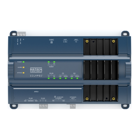
Distech Controls ECLYPSE APEX User manual
Distech Controls
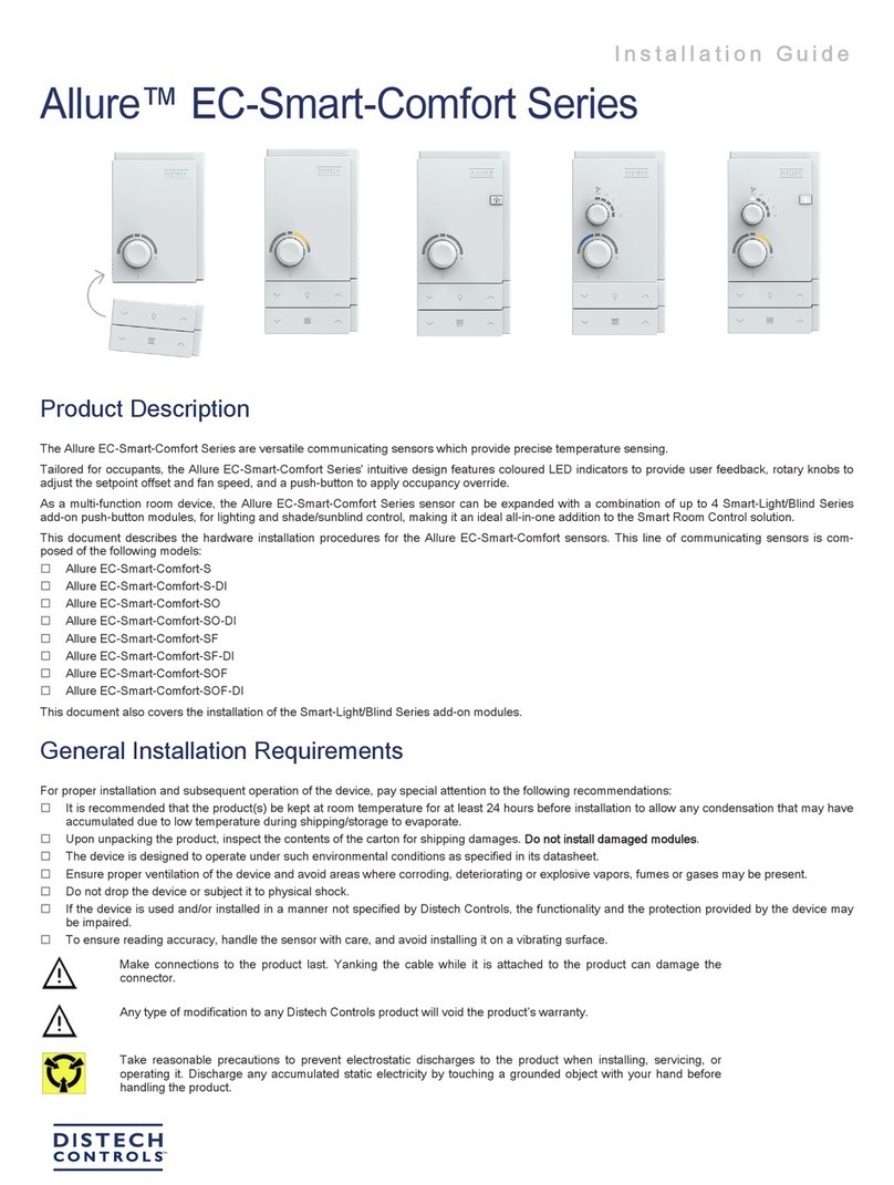
Distech Controls Allure EC-Smart-Comfort Series User manual
Distech Controls
Distech Controls Allure ECW-Sensor Series User manual
Distech Controls
Distech Controls EC-BOS-6AX Programming manual
Distech Controls
Distech Controls DA-020S Series Manual

