Distech Controls UNIWAVE Series User manual

UNIWAVE Series
Product Description
The UNIWAVE Series is a new range of modern wireless interfaces which allows users to manage all comfort settings for a room. Allure UNIWAVE is a
wireless wall-mounted sensor which is particularly suitable for renovation or retrofit projects or areas where wiring is impossible.
General Installation Requirements
For proper installation and subsequent operation of the device, pay special attention to the following recommendations:
£Allow for proper clearance, at least 15cm (6”), around the device’s enclosure to provide easy access for hardware configuration and maintenance.
£The device must not be installed in a place where it can be affected by direct sunlight.
£Install the device in a location of average temperature and approximately 1.5 m (5 ft) above the floor.
£The device should not be installed on an exterior wall.
£The device should not be installed near a heat source.
£The device should not be installed near an air discharge grill.
£Install the device in an area that provides proper device ventilation. Nothing must restrain air circulation to the device.
£Upon unpacking, inspect the contents of the carton for shipping damages. Do not install a damaged device.
£Orient the device with the ventilation slots towards the top to permit proper heat dissipation.
£The device is designed to operate under the following environmental conditions:
– Operating temperature from 32°F to 122°F (0°C to 50°C)
– Storage temperature from 32°F to 122°F (0°C to 50°C)
– Relative humidity from 0% to 80%, non-condensing.
The UNIWAVE device has not been designed for outdoor use.
Any type of modification to any Distech Controls product will void the product’s warranty
Installation Guide

2 / 9
Product Dimensions
Figure1: Allure UNIWAVE dimensions
Figure2: Remote UNIWAVE and wall holder dimensions

3 / 9
Mounting Instructions and Battery Replacement
Allure UNIWAVE
The Allure UNIWAVE must be installed on a clean dry surface using either an adhesive strip (recommended for glass and other smooth surfaces) or by
fastening the backing plate using hardware that is appropriate for the mounting surface.
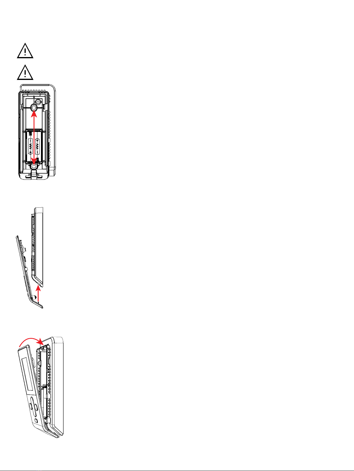
1. To remove the front cover of the unit, begin by loosening the security screw using an appropriately sized hex key.
2. Use a small flat screwdriver to unclip the fastening tab by inserting as shown below. Applying slight pressure towards the left to release the tab.
3. Once the tab has been unclipped, the front cover can be removed. Remove the batteries.
4 / 9
4. With the batteries removed, line up the backing plate to the desired location on the wall. Using the two mounting holes, mark the location of the holes
on the wall to be drilled. Using appropriate hardware for the substrate, drill holes and fasten the mounting plate to the wall. Replace the two (2) AAA
alkaline batteries.
RISK OF SHORT CIRCUIT! The batteries must be removed before screwing the backing plate to the wall.
If replacing the batteries, only use new batteries. Do not use rechargeable batteries with this device. Never mix old and new batteries.
5. To re-attach the front cover, slide the bottom of the front cover upwards as shown below.
6. Make sure the bottom part of the front cover is correctly seated on the backing plate before clipping the top portion back into place. Retighten the se-
curity screw.
5 / 9
Remote UNIWAVE
The Wall Holder for the Remote UNIWAVE can be installed on a clean dry surface using either an adhesive strip (recommended for glass and other
smooth surfaces) or by fastening the backing plate using hardware that is appropriate for the mounting surface. See Product Dimensions [pg.2] for hole
placement.
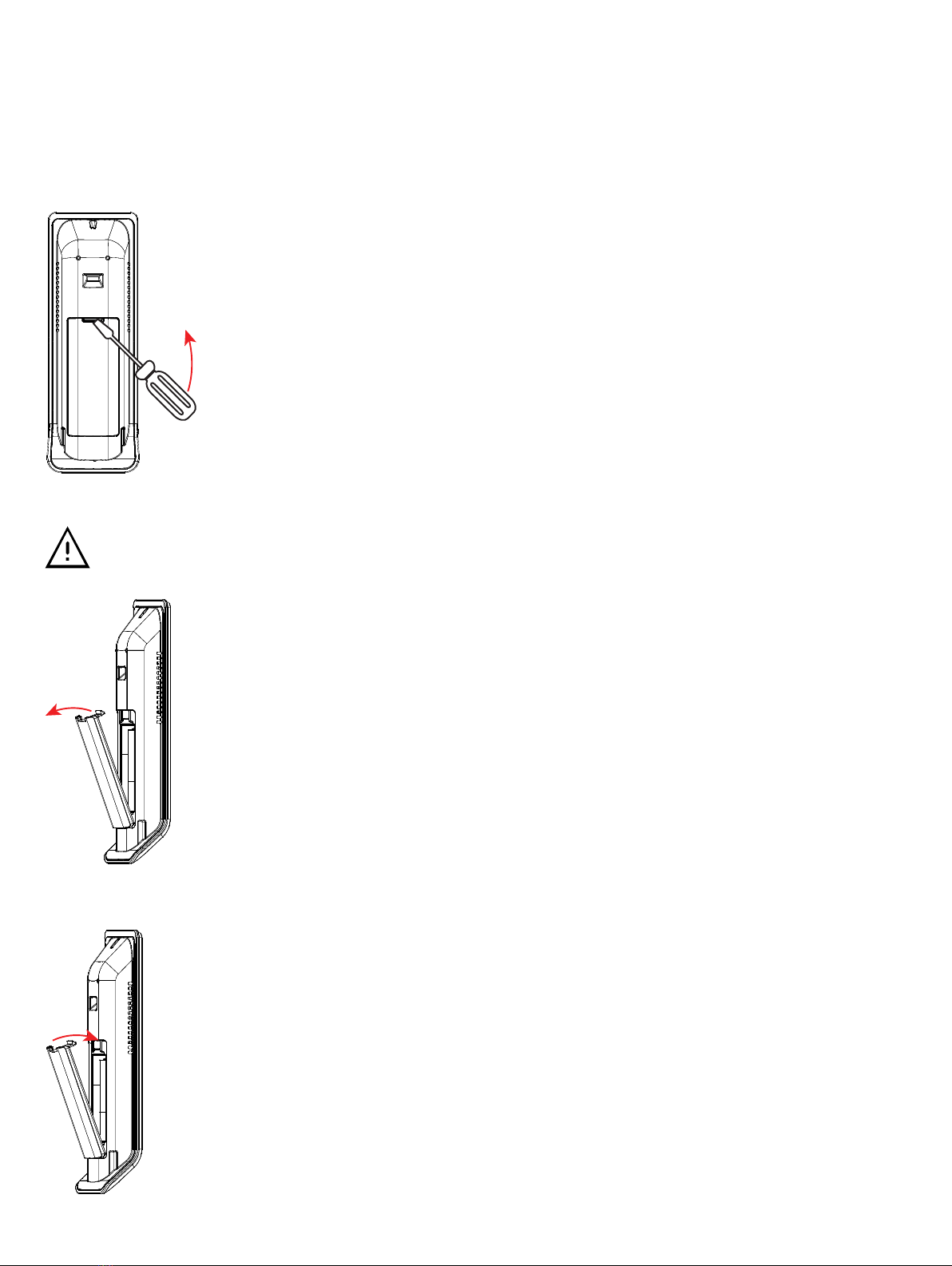
1. Insert a small flat screwdriver in the slot for the battery cover and lever the screwdriver upwards as shown below.
2. Remove the battery cover and replace the two (2) AAA alkaline batteries.
If replacing the batteries, only use new batteries. Do not use rechargeable batteries with this device. Never mix old and new batteries.
3. Replace the battery cover as shown.
6 / 9
Pairing the Device
Before using the UNIWAVE device, it must be paired with the corresponding EC-Multi-Sensor-BLE. To begin the pairing process, you must know the 4-
digit pairing number that has been assigned to the EC-Multi-Sensor-BLE. If the EC-Multi-Sensor-BLE is in Private Connection mode, you must also know
the 6-digit BLE PIN code that is assigned.
Each EC-Multi-Sensor-BLE can be paired with up to two (2) UNIWAVE devices. If two devices are being used, the must each be set to separate chan-
nels.
1. First Connection: Out of the box, the device is in stand-by mode (white screen). Push any button to enter the technician menu.
2. Enter technician mode after first connection: While on the home page, hold down the back button for three seconds.
3. Using the down arrow, navigate to Pairing number, and press OK.
4. Use the navigation buttons to set the 4-digit pairing number that corresponds to the EC-Multi-Sensor-BLE and press OK.
5. From the technician mode screen, navigate down to Remote channel, and press OK.
6. Choose either channel A or channel B for the UNIWAVE device and press OK.
7. Navigate to BLE PIN Code, and press OK.
8. If using Private Connection mode, enter the assigned BLE PIN Code and press OK.
If using Open Connection mode, you must enter the default PIN Code of 000000 and press OK.
Once the pairing process is complete, it may take up to a minute for the device to make the connection and retrieve the BLE configuration for the space.
Once the connection is established, the Room Name associated with the EC-Multi-Sensor-BLE will display at the top of the UNIWAVE device’s screen.
Up to two (2) UNIWAVE Series products plus one (1) mobile phone using the
my
PERSONIFY mobile application can be connected at the
same time on the same EC-Multi-Sensor-BLE
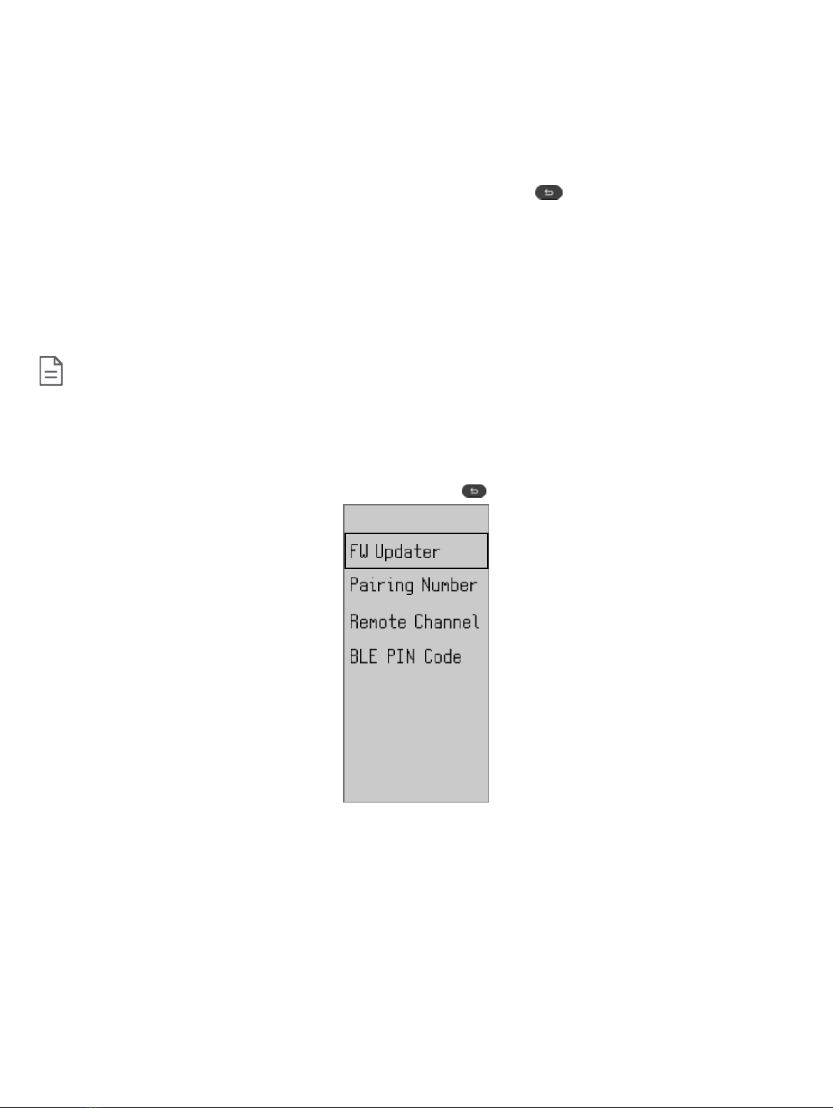
Technician Menu
The Technician Menu contains programming and connectivity settings such as Firmware updates, setting the pairing number, the remote channel and
BLE PIN Code. This menu must only be used by a qualified technician.
To access the Technician Menu, return to the Home Screen and hold the back button for three (3) seconds.

7 / 9
Firmware Updater
The Firmware Updater screen provides device information such as the pairing number, channel, battery status, firmware and bootloader versions, and
model name of the device.
If performing a firmware update, this screen must be displayed for the device to be found.
Pairing Number
Input the pairing number here. The pairing number is required for the UNIWAVE device to connect with the EC-Multi-Sensor-BLE to be able to send and
receive commands. The Pairing Number is configured from the ECLYPSE web interface for the EC-Multi-Sensor-BLE.
Use the UP, DOWN, LEFT, and RIGHT arrows to input the correct pairing number, then press OK to validate your number.

8 / 9
Remote Channel
Up to two (2) UNIWAVE devices can connect to a single EC-Multi-Sensor-BLE, however each UNIWAVE device must be on a separate channel.
Use the UP and DOWN arrows to choose either channel A or channel B. Press the OK button to validate your choice.
BLE PIN Code
The BLE PIN Code is required if the EC-Multi-Sensor-BLE is set to Private Connection.
The BLE PIN Code must be the same one that was assigned to the EC-Multi-Sensor-BLE in the initial programming of the ECLYPSE controller. The BLE
PIN Code can be viewed or changed from the ECLYPSE Web Interface for that specific ECLYPSE controller. This BLE PIN Code is also required for the
my
PERSONIFY mobile application.
Use the UP, DOWN, LEFT, and RIGHT arrows to input the correct Bluetooth PIN Code, then press OK to validate your code.
If you are changing the connection mode from Private to Open, the BLE PIN Code on the UNIWAVE device must also be changed back to
its initial value of 000000.

9 / 9 UNIWAVE_IG_13_EN
Signal Transmission and Connection Guidelines
Transmission range can vary according to building and office setup, therefore it is highly recommended that you always test the signal strength regard-
less of the range distance. To verify the signal strength in any installation, use the RSSI feature with EC-
gfx
Program.
We recommend having a signal between -50 (good signal quality) and -75 (bad signal quality) dBm to ensure a proper connection between UNIWAVE
and EC-Multi-Sensor-BLE.
For more detailed information on the RSSI feature, refer to the EC-
gfx
Program User Guide.
Maintenance and Cleaning
Gently clean the device with a soft, lint-free cloth slightly moistened with a solution of mild liquid dish soap and warm water or disinfect the device with a
soft cloth slightly moistened with a 70% isopropyl alcohol.
Do not directly spray any liquid or disinfecting solution on the device. Do not clean with any other chemicals products.
Disposal
The Waste Electrical and Electronic Equipment (WEEE) Directive set out regulations for the recycling and disposal of products. The WEEE2002/96/EG
Directive applies to standalone products, for example, products that can function entirely on their own and are not a part of another system or piece of
equipment.
For this reason products are exempt from the WEEE Directive. Nevertheless, products are marked with the WEEE symbol , indicating devices are
not to be thrown away in municipal waste.
Products must be disposed of at the end of their useful life according to local regulations and the WEEE Directive.
FCC Statement
Changes or modifications not expressly approved by Distech Controls could void the user's authority to operate the equipment.
This equipment has been tested and found to comply with the limits for a Class B digital device, pursuant to Part 15 of the FCC Rules.
These limits are designed to provide reasonable protection against harmful interference in a residential installation. This equipment
generates, uses and can radiate radio frequency energy and, if not installed and used in accordance with the instructions, may cause
harmful interference to radio communications. However, there is no guarantee that interference will not occur in a particular installation. If
this equipment does cause harmful interference to radio or television reception, which can be determined by turning the equipment off and
on, the user is encouraged to try to correct the interference by one or more of the following measures:
£Reorient or relocate the receiving antenna.
£Increase the separation between the equipment and receiver.
£Connect the equipment into an outlet on a circuit different from that to which the receiver is connected.
£Consult the dealer or an experienced radio/TV technician for help.
This device complies with Part 15 of the FCC rules and with Industry Canada’s license exempt RSS. Operation is subject to the following
two conditions:
£This device may not cause harmful interference, and
£This device must accept any interference received, including interference that may cause undesired operation of the device.
Specifications subject to change without notice.
ECLYPSE, Distech Controls, the Distech Controls logo, EC-Net, Allure, and Allure UNITOUCH are trademarks of Distech Controls Inc. BACnet is a registered trademark of ASHRAE; BTL is a registered
trademark of the BACnet Manufacturers Association. The Bluetooth® word mark and logos are registered trademarks owned by Bluetooth SIG, Inc. and any use of such marks is under license. All other
trademarks are property of their respective owners.
©, Distech Controls Inc., 2019 - 2020 All rights reserved.
Global Head Office - 4205 place de Java, Brossard, QC, Canada, J4Y 0C4 - EU Head Office - ZAC de Sacuny, 558 avenue Marcel Mérieux, 69530 Brignais, France
Table of contents
Other Distech Controls Recording Equipment manuals


