3AST-ASME-ASMI - IP1628
ASMI
Sistema di sfondamento sole ante mobili / Panic system for mobile wings only / Système d’enfoncement
vantaux mobiles seulement / Break-Out-System nur für Fahrflügel / Sistema de desfonde sólo hojas móviles /
Sistema de abertura somente para folhas móveis
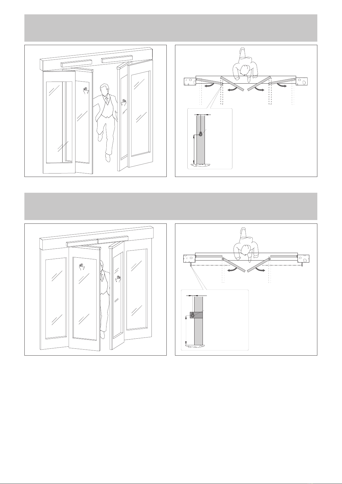
Fig. 5 Fig. 6
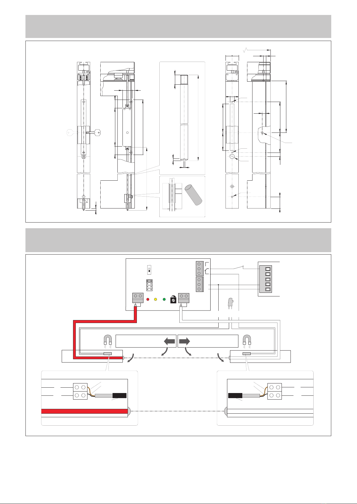
Attenzione: il sistema ASMI è sfondabile solo con ante completamente chiuse.
Warning: the ASMI system can be broken through only when wings are fully closed.
Attention: le système ASMI ne peut être enfoncé que si les vantaux sont complètement fermés.
Achtung: das ASMI System kann nur aufgeschwenkt werden, wenn die Türflügel vollständig geschlossen sind.
Atenciòn: el Sistema ASMI es desfondable únicamente si las hojas están completamente cerradas.
Atenção: o sistema ASMI pode ser aberto somente se as folhas estiverem completamente fechadas.
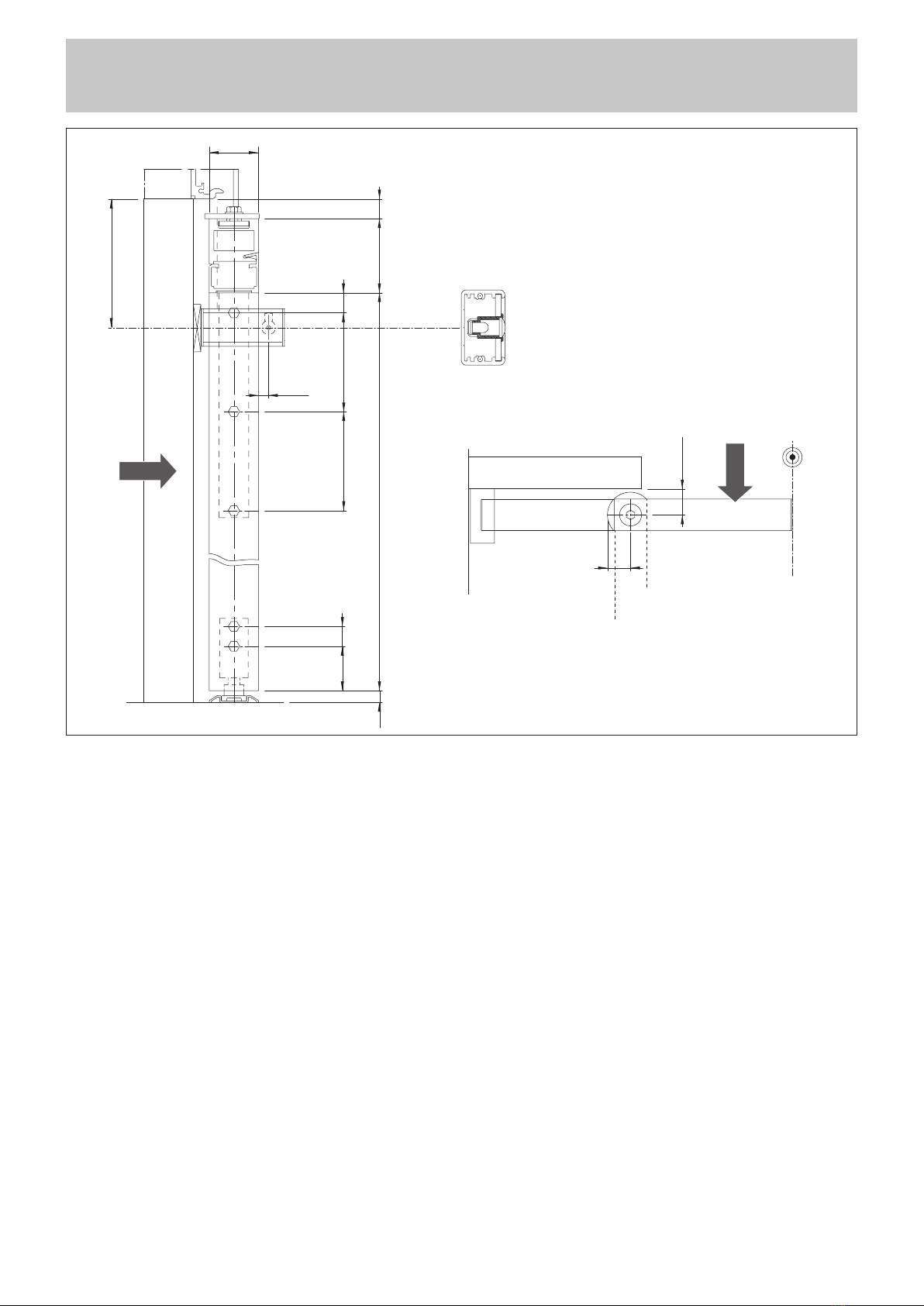
Fotocellula
Photocell
Photocelle
Lichtschranke
Fotocélulas
Fotocélulas
10.5
min. 2000
Attenzione: i sistemi di sfondamento AST, ASME e ASMI sono omologati TÜV solo in abbinamento ad automazioni DITEC modelli BIS-O, BIS-V e TEN
e con l’utilizzo di ante costruite con profili DITEC serie PAM35. L’altezza massima delle ante mobili sfondabili (HM) non deve superare 2400 mm.
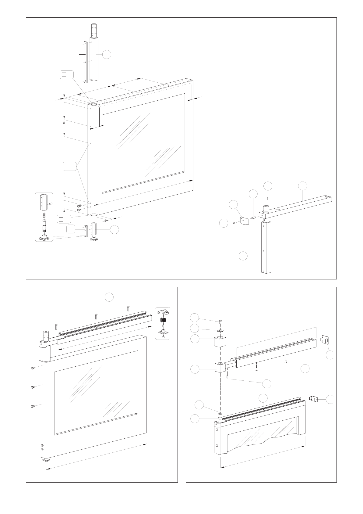
Quando il peso dell’anta fissa è superiore a 100 kg, aggiungere una terza cerniera (vedere KCER2).
(*) Aggiungere il terzo carrello sull’anta.
Warning: break out device AST, ASME and ASMI are TÜV approved only when they are combined with DITEC automations of the BIS-O, BIS-V and
TEN types and with doors with DITEC profiles of PAM35 series. Break-out mobile wings (HM) should not exceed 2400 mm in height.
When the fixed door weighs more than 100 kg, add a third hinge (see KCER2).
(*) Add the third carriage on the wing.
Attention: les systèmes antipanique à enfoncement AST, ASME et ASMI sont homologués TÜV seulement en association avec les automatismes
DITEC modèles BIS-O, BIS-V et TEN, et avec l’utilisation de vantaux réalisés avec les profils DITEC série PAM35. La hauteur maximale des
vantaux mobiles défonçables (HM) ne doit pas dépasser 2400 mm.
Quand le poids du vantail fixe dépasse 100 kg, ajouter une troisième charnière (voir KCER2).
(*) Ajouter un troisiéme chariot sur le vantail.
Achtung: Die Schwenk-Aus-Beschläge AST, ASME und ASMI sind nur in Verbindung mit den DITEC-Antrieben BIS-O, BIS-V und TEN sowie der Verwendung
von DITEC-Profilen der Serie PAM35 TÜV-geprüft. Die Türen mit Schwenk-Aus-Beschlägen (HM) dürfen eine max. Höhe von 2400 mm nicht überschreiten.
Beträgt das Gewicht der festen Tür mehr als 100 kg, fügen Sie ein drittes Scharnier hinzu (siehe KCER2).
(*) Drittes Rollgestellt hinzufügen.
Atención: los sistemas de rotura AST, ASME y ASMI son homologados TÜV sólo combinados con las automaciones DITEC modelos BIS-O, BIS-V y TEN y con el uso
de hojas construidas con perfiles DITEC serie PAM35. La altura máxima de las hojas móviles (HM) que se pueden derribar no tiene que superar los 2400 mm.
Cuando el peso de la hoja fija supera los 100 kg, añadir una tercera bisagra (véase KCER2).
(*) Agregar el tercer carro en la hoja.
Atenção: os sistemas de abertura AST, ASME e ASMI são homologados TÜV somente acompanhados com automações DITEC modelos BIS-O, BIS-V e TEN
e com o uso de folhas fabricadas com perfis DITEC da série PAM35. A altura máxima das folhas móveis da porta anti-pânico (HM) não deve superar 2400 mm.
Quando o peso da folha fixa é superior a 100 kg, adicionar uma terceira dobradiça (vide KCER2).
(*) Adicionar o terceiro carro na folha.
Larghezza anta
Wing width (mm)
Peso massimo singola anta
Single wing maximum weight (Kg)
TEN BISO-V
min. 650 100 120
700 100 120
800 100 120
900 80 110
1000 70 110
1100 60 100
1200 / 100 (*)
1300 / 90 (*)
1400 / 80 (*)