olympia electronics DLD-28/CBS/w User manual

GENERAL
These new illumination signs use a new
technology, friendly to the environment ,
with high illuminated L.E.D.s. L.E.D.
technology has very low power consumption.
The edge illumination sign is used as a
mains lighting with indications symbols for
central battery systems (CBS).
In this type of marking panels, the PVC
overlay is mounted on the marking panel
with 4 plastic screws, and it can be changed
by change the PVC overlay in accordance
with the marking code.
Each model combines modern, aesthetics,
to ge th er wi th fu nc ti on al it y. The ex it
illumination signs are used in every public
area wh ere clear direction an d good
appearance are important. All models must
be permanently connected to the mains
power supply as shown on page 2.
The legend is screened on to a clear acrylic
sheet which has the marking on the marking
panel with the light that comes from the top
of the luminaire and diffracts, giving light to
the marking panel.
The unit must be mounted in a clearly visible
area and can either be hung on a ceiling or
mounted on a wall depending on the
requirements of the installation. The
package includes all the required materials
for mounting on the wall or on the ceiling.
Pages 2, 3 and 4 show the mounting
methods.
WARNING !!
1. Th e uni t mus t be co nnec t ed to a
dedicated fused power line, for example 16A
rating.
NOTE: LED= Light Emitting Diode
LABELING EXPLANATION:
Z: Central supply
1: Maintained
G: Internally illuminated
The light source contained in this
luminaire shall only be replaced by the
manufacturer, or his agent, or a similar
qualified person.
NOTE! The light source is non-user
replaceable.
Page 1 from 5
CBS EDGE ILLUMINATION SIGNS WITH WHITE LEDs
922604410_09_029
Thank you for your trust in our products.
Olympia Electronics - European manufacturer.
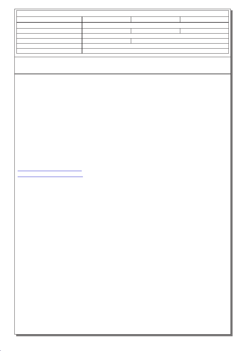
TECHNICAL CHARACTERISTICS (for LED MODULE Specs. see page 5)
40-250V DC-AC/50-60Hz
IP42
125lm
100lm
1.5W/4.5VA
EN 60598-1, EN 60598-2-22, ΕΝ 55015, ΕΝ 61547, ΕΝ 61000-3-2, ΕΝ 61000-3-3
-30 to 50 ºC
up to 95%
280x100mm
3 years
465gr. 795gr. 1270gr.
340x170mm 440x220mm
DLD-34/CBS/w DLD-44/CBS/w
DLD-28/CBS/w
Operation temperature range
Relative humidity
External panel's dimensions
External dimensions
Typical weight
Guarantee
Mains voltage
Maximum power consumption
Degrees of cover protection
Produced in accordance with
Light source intensity
305x25x155mm 365x25x225mm 465x25x275mm

Page 2 from 5
Preparation procedure
for ceiling mounting
Connection of the included terminal block
LL
NN
230V AC
BROWN
GREY
Attention!!! Interrupt the mains power supply.
Mounting methods
2. Place the plastic part for mounting the sign.
1. Open the pre-etched knock out and pass
the cable through.
3. Place the cable holding accessory and mount it by
tightening the screw with the included grommet.
4. Connect the wires to the included terminal block and place it
in the plastic mounting part.
5. Follow the procedure bellow (figure 1).
Hanging installation on
suspended ceilings using the
special mounting brackets
contained in the package.
DLD-28 S: 29.5cm
DLD-34 S: 35.7cm
DLD-44 S: 45.7cm
2
S1
4
3
Hanging installation on
suspended ceilings using the
special mounting brackets
Figure 1
1. Attention!!! Choose the installation area to insure that the mounting surface is appropriate for the
installation of the illumination sign.
2. Measure the space S according to the illumination sign’s type and drill the appropriate holes in the
ceiling for the installation of the included mounting plugs Nr 6.
3. Place the mounting plugs Nr 6 and mount the sign by tightening the included mounting screws.
4. Refit the plastic cover on each side.
5. Power the illumination sign and check the illumination sign’s operation.
Recessed mounted installation
on suspended ceilings using
the base type Α-1018/PL,
Α-1020/PL, Α-1021.
A-1018/PL
280
A-1020/PL
342
75
75
A-1021
440
75
Ø6
Ø6
Ø6
Suspended ceiling mounting bases
Ceiling mounting
922604410_09_029

Page 3 from 5
4. Connect the wires to the included terminal block and place it
in the plastic mounting part.
1. Place the plastic mounting part
5. Place the mounting accessories in the
wall and tighten the mounting screw.
2. Tighten the screw
3. Pass the cable in the canal
6. Place the plastic cover.
S2
DLD-28 S: 22cm
DLD-34 S: 28cm
DLD-44 S: 37.5cm
Use a certified electrical box 250V AC (IP40) to
perform the electrical connection, with minimum
internal space 35x35x25mm to install the 3 pole
terminal block. In this box install a certified 3 pole
terminal block 250V AC/16A 2,5mm² providing
terminals to connect the live wire L, the neutral N
and the ground GND. To this terminal block is
connected the power cable with a cross section of
1,5mm². Install the electrical box in an appropriate
area in the ceiling. Install securely the 3 pole
terminal block and perform the connection according to figure 3.
The electrical box and the 3 pole terminal block are not provided by olympia electronics.
Electrical box
(Not included)
Figure 2
ELECTRICAL BOX INSTALLATION
1. Attention!!! Interrupt the mains power supply.
2. Perform the preparation procedure for ceiling mounting on
page 2 and exclude step 4.
3. Perform the procedure for ceiling mounting figure 1.
4. For the installation of the electrical box you may need to
open holes in the ceiling and at it’s cable entrances, for the
entrance of the power and illumination sign’s cables. Install the electrical box next to the sign so as to
cover the cable (figure 2).
5. After mounted the electrical box open the cover and perform the electrical connection according to
Figure 3. After the connection close the cover of the box.
6. Power the illumination sign and check the illumination sign’s operation.
OPTIONAL !!
When a triple core cable must be used, then follow the figures 2,3 bellow.
Ceiling mounting
40-250V DC-AC/50-60Hz
GREY
L
GND
NBROWN
Electrical
box
Figure 3
922604410_09_029

Page 4 from 5
2. Place the plastic part
1. Open the pre-etched knock out and pass the
cable through.
3. Place the cable holding accessory and mount it by
tightening the screw with the included grommet.
5. Place the mounting accessories in the wall
and tighten the mounting screw figure 1 step 3.
6. Place the plastic cover.
Wall in bottom view
Wall mounted installation
using the special mounting
brackets contained in the
package.
Flag mounted installation on
a wall using the special
mounting bracket contained
in the package.
2. Place the single mounting plastic part
3. Tighten the mounting screw.
1. Open the pre-etched knock out and pass the cable
through.
5. Place the mounting accessories in the wall
and screw the mounting screws
Wall mounting
4. Connect the wires to the included terminal block and
place it in the plastic mounting part.
6. After finishing the installation, secure the cable with a
suitable cable detention bracket (not included) to ensure
immobilization of the cable at a distance of no more than
5cm from the luminaire’s cable entry.
4. Connect the wires to the included terminal block and
place it in the plastic mounting part.
6
Electric connection and Eco Light dimensions in mm
DLD-28 : 305(a) x 95(b)
DLD-34 : 365(a) x 165(b)
DLD-44 : 465(a) x 215(b)
b
60mm
a
L N
40-250V DC-AC/50-60Hz
Package contents
The package contains:
1. The illumination sign
2. The instructions manual
3. Plastic bag with supporting
materials.
Package contents
922604410_09_029

WARRANTY
Olympia Electronics guarantees the quality, condition and operation of the goods. The period
of warranty is specified in the official catalogue of Olympia Electronics and also in the
technical leaflet, which accompanies each product. This warranty ceases to exist if the buyer
does not follow the technical instructions included in official documents given by Olympia
Electronics or if the buyer modifies the goods provided or has any repairs or re-setting done
by a third party, unless Olympia Electronics has fully agreed to them in writing. Products that
have been damaged can be returned to the premises of our company for repair or
replacement, as long as the warranty period is valid.
Olympia Electronics reserves the right to repair or to replace the returned goods and to or not
charge the buyer depending on the reason of defection. Olympia Electronics reserves the
right to charge or not the buyer the transportation cost.
HEAD OFFICE
72nd km. O.N.R. Thessaloniki-Katerini
P.C. 60061 Greece
www.olympia-electronics.gr
LED MODULE CHARACTERISTICS
Olympia Electronics S.A
45 °C max. across the board
Fixed connection between main pcb and led module
8.5-10.5V DC
980mW
1802161
800mW
1702161 3005111
DLD-28/CBS/w
DLD-34/CBS/w
DLD-44/CBS/w
Manufacturer
Model Number
Voltage Range
Connections
Nominal Power
Temperature (tc)
Page 5 from 5
ATTENTION!! If the external flexible cable or cord of this luminaire is damaged, it shall be exclusively
replaced by the manufacturer or his service agent or a similar qualified person in order to avoid a hazard.
922604410_09_029
This manual suits for next models
2
Table of contents
Other olympia electronics Safety Equipment manuals