15272 Newsboy Circle
Huntington Beach
California 92649
Phone: 714-751-0488
Fax: 714-896-9679
Each Form-C alarm output relay has a separate wiring terminal. These terminals are located along the right-hand side of
the circuit board with “Alarm 1” at the top, and “Alarm 8” at the bottom.
The alarm relay terminals accept wire sizes 18-22 AWG.
End Of Line Resistors: If desired, an in-series “End of Line” supervision resistor may be installed on the screw terminals
adjacent to the relays. Any EOL resistors placed here will be “in-series” with the Common terminal of the Form-C relay. If
these EOL terminals are not used, they must be shorted across, so that the Common terminal of the relay is presented to
the wiring block.
4) Connection to piezo-beeper: A single expansion slot is provided near the upper center of the circuit board. Standard
annunciator models ship from the factory with a single weatherproof NEMA-4 piezo beeper connected to this expansion
slot.
Additional accessories may be available, now or in the future, and each such accessory item shall be accompanied by
an instruction sheet describing its use of the expansion slot pins, if any.
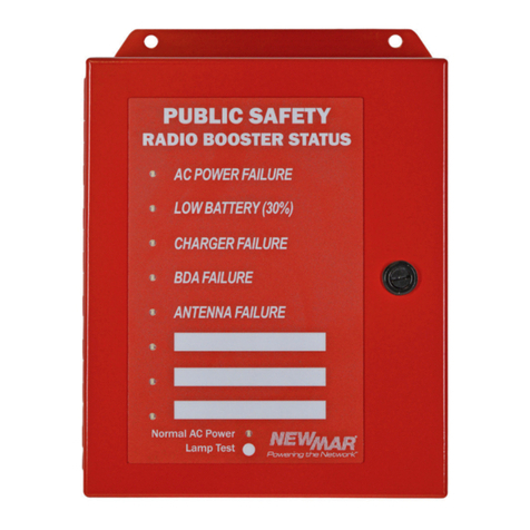
5) Press-to-Test Button: The annunciator is equipped with a “Press-to-Test” button. When pressed, all front panel LED’s will
illuminate. (The piezo beeper and alarm relay outputs do not activate.)
6) Buzzer ‘Silence” Button”: Located near center of PCB. Press to silence. If alarm still active after 24 hours, buzzer will sound.
Summary Alarm Option (Auto Dialer)
The AP-8000A can be set to activate relay #8 whenever any one or more of the alarm inputs (#1 - #7) are activated. This
summary alarm can be used to activate an Auto Dialer for example.
To set relay #8 for summary alarm:
1. Disconenct power from AP-8000A
2. Open the door on the front of the AP-8000A
3. Identify DIP switch to the left of the main microprocessor (refer to Figure 1 on page 2 for location of DIP switches)
4. Set DIP switch #3 in the ON position
5. Re-connect power to the AP-8000A
6. Test, attach a continuity checker across the NO terminals of relay #8 and activate any alarm (example: turn BDA
Battery back up power battery breaker in the OFF potion momentarily). Confirm relay #8 activates
Programming and RS-485 Features
Function Switch: 4-Position DIP switch (left of processor):
Switch-1 = Beeper OFF/ON (Off = No beeper, On = Beeper will sound on alarms)
Switch-2 = Relay contact selection (ON=Normally Closed/Contact Open activates alarm, OFF=Normally Open/Conact
Closure activates alarm)
Switch-3 = Additional feature (On = Alarm Relay 8 becomes a combined alarm output, Off = Alarm Relay 8
behaves normally)
Switch-4 = Selects Master/Remote (Off = Master, On = Remote)
Address Switch: 4-Position DIP switch (right side of processor): This sets the annunciator address in binary. (0-15)
*Power Failure Alarm Contact: See Figure 2 for location. Two position plug-able terminal block. Normally Closed when
power to Annunciator is ok, opens upon loss of power.
RS-485:
• 4800 Baud, no parity, 8-data bit word, 1 stop bit, half-duplex.
• Maximum # annunciators: 16 (i.e., 1 Master and up to 15 remotes)
• The last annunciator panel, if connecting multiple annunciators should be terminated for best performance
• Maximum bus length: 4,000 feet when using 22-ga twisted shielded pair (CAT 5e cable)
• There can only be (1) Master assigned per system. Only the Master accepts alarm inputs from the BDA/BBU (on the
orange and green push-connector).
• The remote(s) ignore connections on their orange and green push-connector.
• If a remote(s) loses its RS-485 connection for more than a few seconds, that remote will disengage all its output relays
and begin to cycle the membrane keypad LED’s from top to bottom until the RS-485 link is reconnected. Upon
reconnection, the remote will operate normally.
• Yellow TX & RX LED’s indicate the bus status.
Note: When not in use, the TX and RX LED’s may or may not flash - this is normal.
3


