Assa Abloy SARGENT 9400 Series User manual

1-800-727-5477 • www.sargentlock.com
A7828B 01/23
Installation Instructions
9400 & 12-9400 Series
Narrow Style Cross Bar Concealed Vertical Rod Exit Devices
Copyright © 2009, 2023, SARGENT Manufacturing Company. All rights reserved. Reproduction in whole or in part without the express
written permission of SARGENT Manufacturing Company is prohibited. Patent pending and/or patent www.assaabloydss.com/patents.
WARNING
This product can expose you to
lead which is known to the state of
California to cause cancer and birth
defects or other reproductive harm.
For more information go to www.
P65warnings.ca.gov.
Attention Installer: Improper
installation may result in dam-
age to the product and void the
factory warranty.
WARNING

2
1-800-727-5477 • www.sargentlock.com A7828B 1/23
9400 & 12-9400 Series
Installation Instructions
Narrow Style Cross Bar CVR Exit Deviced
Copyright © 2009, 2023, SARGENT Manufacturing Company. All rights reserved. Reproduction in whole or in part
without the express written permission of SARGENT Manufacturing Company is prohibited. Patent pending and/or
patent www.assaabloydss.com/patents.
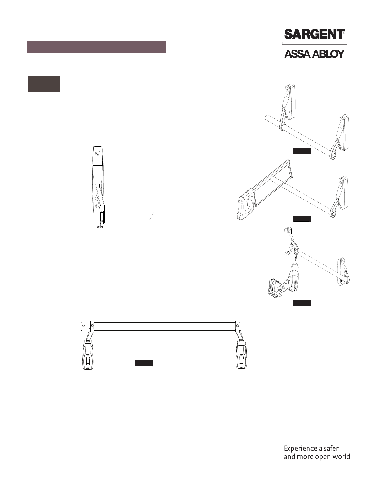
1. Place cover from present active case onto
inactive case, engaging lift finger with
bottom of slide.
2. Place cover from inactive case on active
case, engaging lifting finger with bottom
slide. Be sure that nylon button on back of
the cover fits into the hole in the plate.
Before installing, verify hand of door & read instructions.
1
Change hand of device.
2
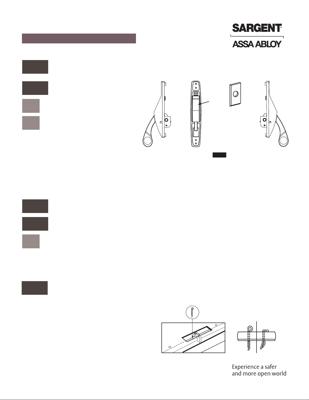
Figure 1 Inactive Case
Active Case
Plate
Rounded End
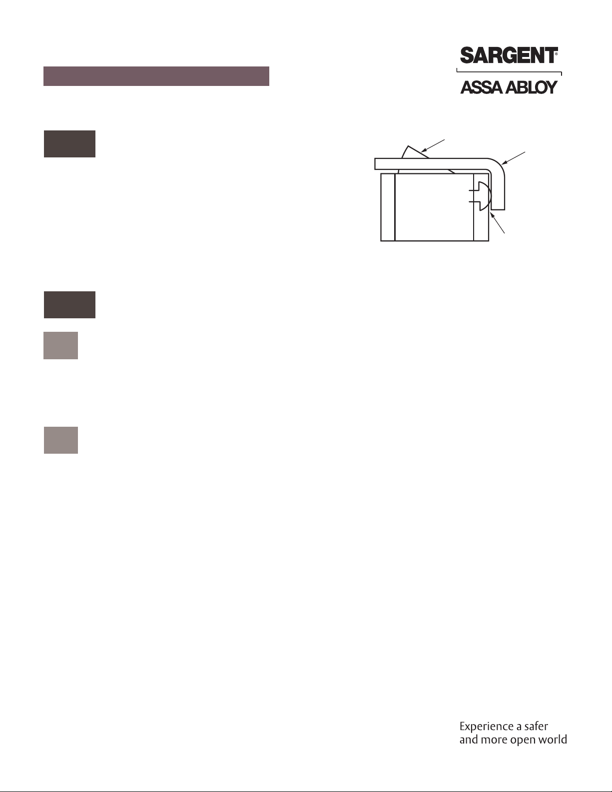
Note: Be sure that plate with hole in it is positioned in the active case as shown with the rounded end
down.
Prepare door and frame.
3
Insert rods and secure top latches and bottom bolt.
4
aRemove case cover.
bSwitch case covers and reassemble.
aConcealed Mounting
1. Attach mounting brackets to cases of top latch and bottom bolt.
2. Slide bottom tube into bottom of stile. Secure with screws.
3. Retract top latch by holding case and pushing up on rod. Insert top latch rod into top of stile and into
bottom tube. Secure with screws.
Pin top rod and bottom tube.
5
Using access hole, raise lifting flange for active case
so that bottom bolt is fully retracted. Do not press
bottom bolt from botton of the door. Confirm that
the top latch is retracted. Drill 1/8” diameter hole
through rod and tube, using predrilled hole in bot-
tom tube as a guide. Insert hammer lock cotter pin
through hole and secure with punch and hammer
Flatten pin head completely. Hang door.
Drill Through
Guide Hole Inserted Flattened

3
1-800-727-5477 • www.sargentlock.com
Copyright © 2009, 2023, SARGENT Manufacturing Company. All rights reserved. Reproduction in whole or in part
without the express written permission of SARGENT Manufacturing Company is prohibited. Patent pending and/or
patent www.assaabloydss.com/patents.
A7828B 1/23
9400 & 12-9400 Series
Installation Instructions
Narrow Style Cross Bar CVR Exit Deviced
Install active case.
6
Undog cases using supplied key. Back out screw and
remove tenon from active case lever. Mount active
case engaging hook under lifting flange. Secure
with screws supplied.
Lifting
Flange
Test operation.
7
Push down on active case lever to be sure top and
bottom bolt retract completely and remain retract-
ed when lever is released. If bottom bolt does not
retract flush with the bottom of the door, check Step
5 procedure.
Install inactive case.
8
Place case in position. Level with the active case. Drill
and tap for 1/4-20 screws and then mount.
Top Strike
Mounting
Bracket
Top Latch
Top Rod
Lifting Flange for
Outside Operator
Outside Operator
Active case
Lifting Flange
for Active Case
Dogging Hole
Cotter Pin Hole
Felt Deadener
Bottom Bolt
Operating Tube
Tension Spring
Mounting
Bracket
Bottom Bolt
PlugScrew

4
1-800-727-5477 • www.sargentlock.com A7828B 1/23
9400 & 12-9400 Series
Installation Instructions
Narrow Style Cross Bar CVR Exit Deviced
Copyright © 2009, 2023, SARGENT Manufacturing Company. All rights reserved. Reproduction in whole or in part
without the express written permission of SARGENT Manufacturing Company is prohibited. Patent pending and/or
patent www.assaabloydss.com/patents.
9Install crossbar
Alternately push down on one lever while pushing up on other.
Note: If after completion of installation, crossbar does not work freely, check installation of binding of
levers due to improper bar length or case misalignment.
1. Slide bar through active and inactive case with screw hole
towards active case. Screw plug and bar onto active case with
10-24 x 3/4” cap screw. (Figure 2)
Figure 3
2. Mark bar at inactive case and cut. Length of cross bar should be
from flush to 1/16” less than flush. (Figure 3)
3. Drill 3/16” hole thru one side of bar using hole in arm to locate.
(Figure 4)
4. Slide plug into bar with holes aligned and attach with 10-24 x
3/4” cap screw. (Figure 5)
Figure 4
1/16” MAX
Figure 2
Figure 5

5
1-800-727-5477 • www.sargentlock.com
Copyright © 2009, 2023, SARGENT Manufacturing Company. All rights reserved. Reproduction in whole or in part
without the express written permission of SARGENT Manufacturing Company is prohibited. Patent pending and/or
patent www.assaabloydss.com/patents.
A7828B 1/23
9400 & 12-9400 Series
Installation Instructions
Narrow Style Cross Bar CVR Exit Deviced
10 Install outside trim
Note: If door offers too much resistance to the self tapping screws, use an 11/64" diameter drill.
aPrepare door for trim using template supplied, determine and
mark backset on outside of door.
bPress in top latch plunger screw to project top latch and bottom
bolt. Place trim in locked position.
cCenter trim on center line of backset, so top side of the lifting lever
contacts underside of the auxiliary lifting flange.
dMark door through hole at the top of the trim.
eDrill starting hole with a #18 drill for self tapping screws.
fMount trim with screws supplied.
gUnlock trim to retract latch and bolt.
hSpot and drill hole with the same #18 drill for self tapping screw.
11 Strike installation
Top Strike
Bottom Strike
Install top strike to header with screws supplied. Mortise
bottom strike into floor, in line with the center line of the
bottom bolt. If metal threshold is used, drill 7/8" diameter
inline with bottom bolt.

6
1-800-727-5477 • www.sargentlock.com A7828B 1/23
9400 & 12-9400 Series
Installation Instructions
Narrow Style Cross Bar CVR Exit Deviced
Copyright © 2009, 2023, SARGENT Manufacturing Company. All rights reserved. Reproduction in whole or in part
without the express written permission of SARGENT Manufacturing Company is prohibited. Patent pending and/or
patent www.assaabloydss.com/patents.
12 Adjusting plunger screw
Top of
Door
Top Strike
Top Latch
Plunger Screw
Just Touching
Top Strike
As the door closes against the top strike, the plunger screw
should be adjusted such that upon contact with the top
strike, both the top and bottom latch points engage the
frame.
13 Test operation
aFrom the outside
The key will retract the top latch and bottom bolt. Once retracted, the latch and bolt must remain in
the retracted position until the door closes and the plunger screw comes in contact with the top strike,
releasing both the latch and bolt.
bFrom the inside
The door is opened by pressing the cross bar, retracting the top latch and bottom bolt simultaneously.
Once retracted the latch and bolt must remain in the retracted position until the door closes and the
plunger screw comes in contact with top strike, releasing both latch points.
When the cross bar is in the dogged position and locked, both latch points should be fully retracted.

7
1-800-727-5477 • www.sargentlock.com
Copyright © 2009, 2023, SARGENT Manufacturing Company. All rights reserved. Reproduction in whole or in part
without the express written permission of SARGENT Manufacturing Company is prohibited. Patent pending and/or
patent www.assaabloydss.com/patents.
A7828B 1/23
9400 & 12-9400 Series
Installation Instructions
Narrow Style Cross Bar CVR Exit Deviced

A7828B 1/23
This manual suits for next models
1
Table of contents
Other Assa Abloy Safety Equipment manuals

Assa Abloy
Assa Abloy 179A User guide

Assa Abloy
Assa Abloy SARGENT 57 Series User manual

Assa Abloy
Assa Abloy 179B User guide

Assa Abloy
Assa Abloy PDU8500 Series User manual

Assa Abloy
Assa Abloy PDU8000 Series User manual

Assa Abloy
Assa Abloy Securitron EEB2 Manual

Assa Abloy
Assa Abloy SARGENT Beacon User manual
Popular Safety Equipment manuals by other brands

Saxby Lighting
Saxby Lighting Nova Instruction leaflet

Omron
Omron Sti F3SJ-B P25-01TS Series Quick installation manual

Spanset
Spanset Gotcha Shark User information

ejendals
ejendals jalas 20345 User instructions

VERTIMA
VERTIMA railoc Assembly and maintenance instructions

Husqvarna
Husqvarna X-SYNC Operator's manual