DIVERSITECH D MISTER Manual

Operation & Maintenance Manual
D MISTER VERTICAL OIL MIST COLLECTOR
Visit our Website for more information on this product
www.diversitech-air.com www.diversitech.ca
1200 55th Avenue, Montreal, Quebec H8T 3J8
READ AND SAVE THESE INSTRUCTIONS

TABLE OF CONTENTS
Safety …………………...…………………….............................................................................................................................................................................................................................................................................……………. 3
Inspection ................................................................................................................................................................................................................................................................................................................................... 3
Specifications ……………….……………....................................................................................................................................................................................................................................................……….……………………... 4
Installation ………………………………….....................................………......................................................................................................................................................................................................................…………………… 5
Replacement Parts ………………………..............................................................................................................................................................................................................................................………….……………………. 6
Optional Direct Drive Replacement Parts ............................................................................................................................................................................................................................................................... 7
3 Phase Electrical Diagram ..............................…......................................................................................................................................................................................................................…………..……………………. 8
Motor Mounting ...................................................................................................................................................................................................................................................................................................................... 9
Connecting Power to Motor ........................................................................................................................................................................................................................................................................................ 10
Motor Troubleshooting Chart ….….................….........................................................................................................................................................................................................................…………….…………..…. 11
Blower Operation ................................................................................................................................................................................................................................................................................................................ 12
Notes .......................................................................................................................................................................................................................................................................................................................................... 14
TERMS AND CONDITIONS TO SALES ORDERS...................................................................................................................................................................................................................................18,19
Back Cover...............................................................................................................................................................................................................................................................................................................................20
Revised October 2019 [E N]

3
SAFETY
PLEASE READ THE FOLLOWING INSTRUCTIONS CAREFULLY BEFORE
INSTALLING, OPERATING OR SERVICING YOUR AIR CLEANER.
Follow all building and safety codes when installing this equipment. Pertaining but not limited to, the Occupational
Safety and Health Act (OSHA), National Electric Code (NEC), Uniform Building Code (UBC), National Fire
Prevention Act (NFPA) & all state and local codes.
All electrical connections should be performed by a qualified electrician.
Keep Flammable Objects away from the air cleaner and under no condition should a burning object be allowed
into the air cleaning system.
Take proper caution in placing units in buildings with radiant heaters installed. Follow the radiant heater
manufacturer’s guidelines for clearance to combustibles.
Do not mix materials collected in your Air Cleaner. Materials collected could create a hazardous environment or a
condition of operation for which the equipment was not intended. The Manufacturer is relieved of any liability if this
unit is not used according to this manual.
Do not use the Air Cleaner for an application other than for which it was intended. Consult your distributor,
Applicable Codes, or call Diversitech for application assistance.
Fire protection is not included. Please consult your local fire protection specialist for any required extinguishing
equipment.
Consult with your insurance underwriter about any other protection from fire damages.
The Manufacturer reserves the right to make design changes which may improve the air cleaner.
This unit is intended for use to collect coolant, mist, smoke, fume and other airborne pollutants in industrial and
manufacturing Facilities. Do not use for the collection of flammable or explosive metals, dusts, fumes or other
potentially hazardous materials.
INSPECTION
Upon receiving your Diversitech air cleaner, please inspect for any damage incurred during shipment. Inspect
carefully, some damage may not be noticeable until the unit is installed. Notify your shipper of any damage
immediately. Claims must be filed with the shipper within 15 days. Freight damage claims are the responsibility of
the purchaser.

4
12 & 14 ga powder coated steel frame. 16 ga. steel doors. 3/16 polyethylene panels
(14 ga . steel panels, optional). Adj. compression hinges, cam door and filter latches.
DM 2000V - 110”H x 26”W x 25”D DM 4000V - 110”H x 48”W x 36”D
DM 2000V - 285 lbs. DM 4000V - 620 lbs.
3/4 HP - 230/460/1/60 TEAO 3.4/1.7 FLA
2.0 HP - 208-230/460/3/60 6.0-5.8/2.9 FLA
3.0 HP - 230/460/3/60 8.6/4.3 FLA
3/4 HP - 3000 CFM @ .6” W.G. *Direct drive BI options available
2.0 HP - 3500 CFM @ 1.0” W.G.
3.0 HP - 4500 CFM @ .85” W.G.
10 x 10 Forward Curve Blower Belt Drive (3/4 - Direct Drive)
4-way aluminum exhaust grille
Prefilter - 2” Baffle
Secondary - 2” Mist Eliminator
Final - 95% bag Filter
Optional - Aluminum Mesh
26 lb. Carbon
Module 99.97% HEPA
Afterfilters
Cabinet
Size
Weight
Electrical
(wired to
Jct. box)
Air Volume*
Blower
Exhaust
Filters
SPECIFICATIONS
Diversitech Model D Mister Vertical Oil Mist Collector
5
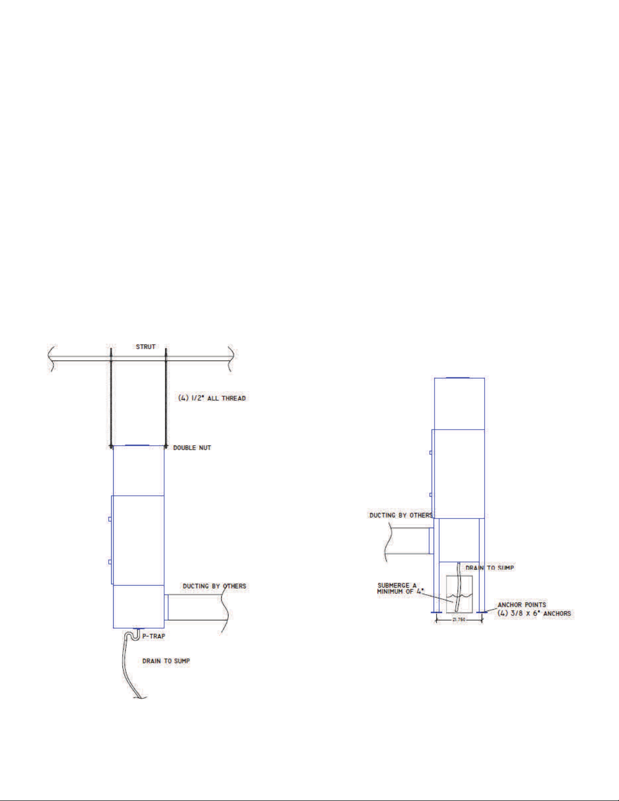
INSTALLATION
The standard Diversitech D Mister is intended for source capture coolant application and will require some
mechanical installation. Units are typically mounted on the optional floor stand or rod hanging brackets illustrated
in Figure 2.
Duct work may be required to complete installation which is not supplied by Diversitech. Consult your dealer or
the factory for the correct materials to use for your application. A qualified mechanical contractor should be used
to ensure unit installation meets all applicable building codes.
Each unit is supplied with a 1-1/4 NPT drain in the sump of the unit. The drain must be correctly connected to the
machine tool sump or external reservoir prior to operation of the mist collector. The inlet plenum of the collector
is not intend to act as a reservoir for the collected coolant and must drain properly for the unit’s performance.
A trap should be used to make sure air does not flow through the drain into the collector. A good alternative
to a standard p-trap, is to submerge the end of the drain line, into at least 4 inches of coolant. This will prevent
backflow and also eliminate clogs which may form in a p-trap. Both methods are illustrated below.
Figure 2.
6
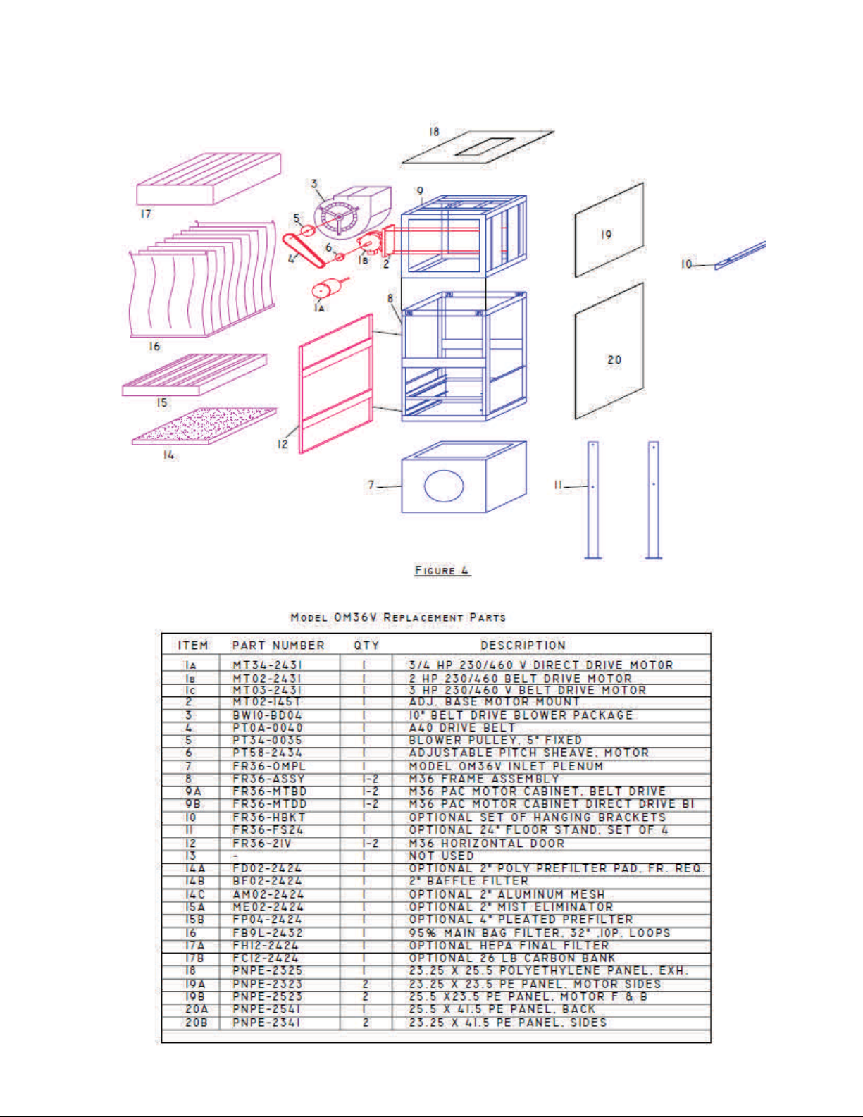
REPLACEMENT PARTS - FIGURE 4
7
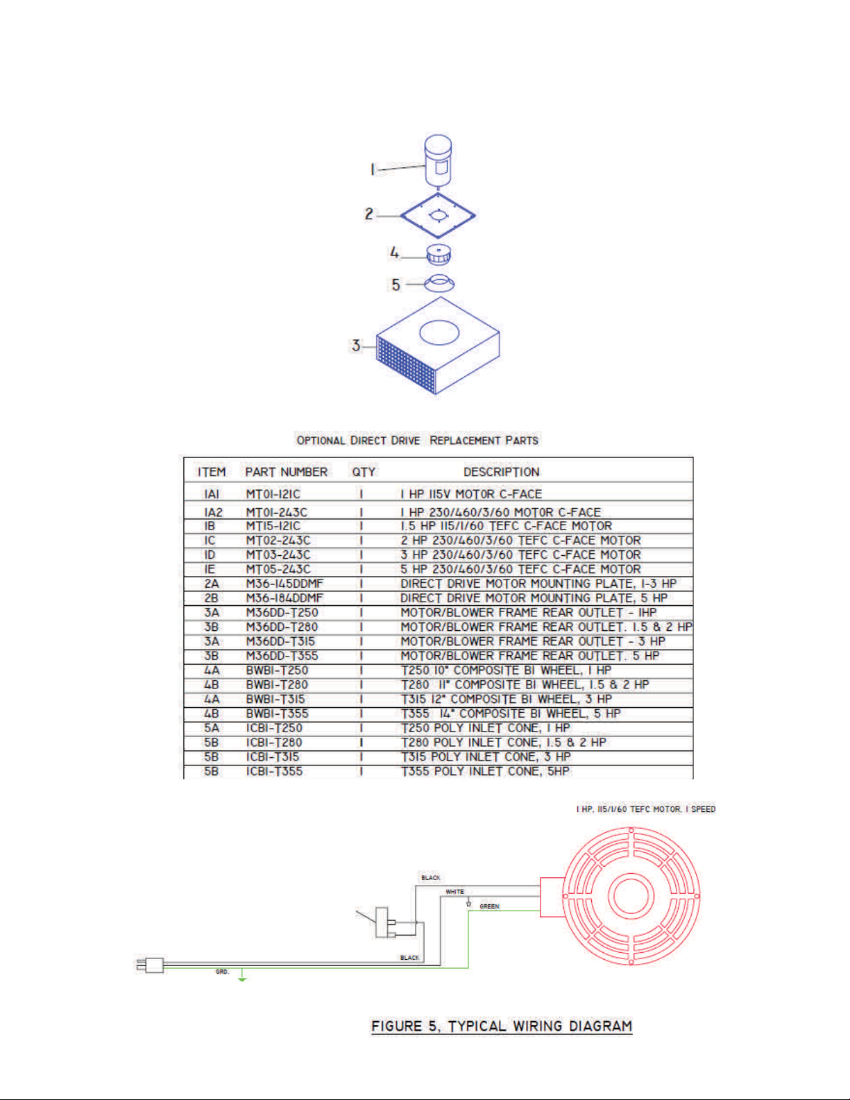
OPTIONAL DIRECT DRIVE REPLACEMENT PARTS
8
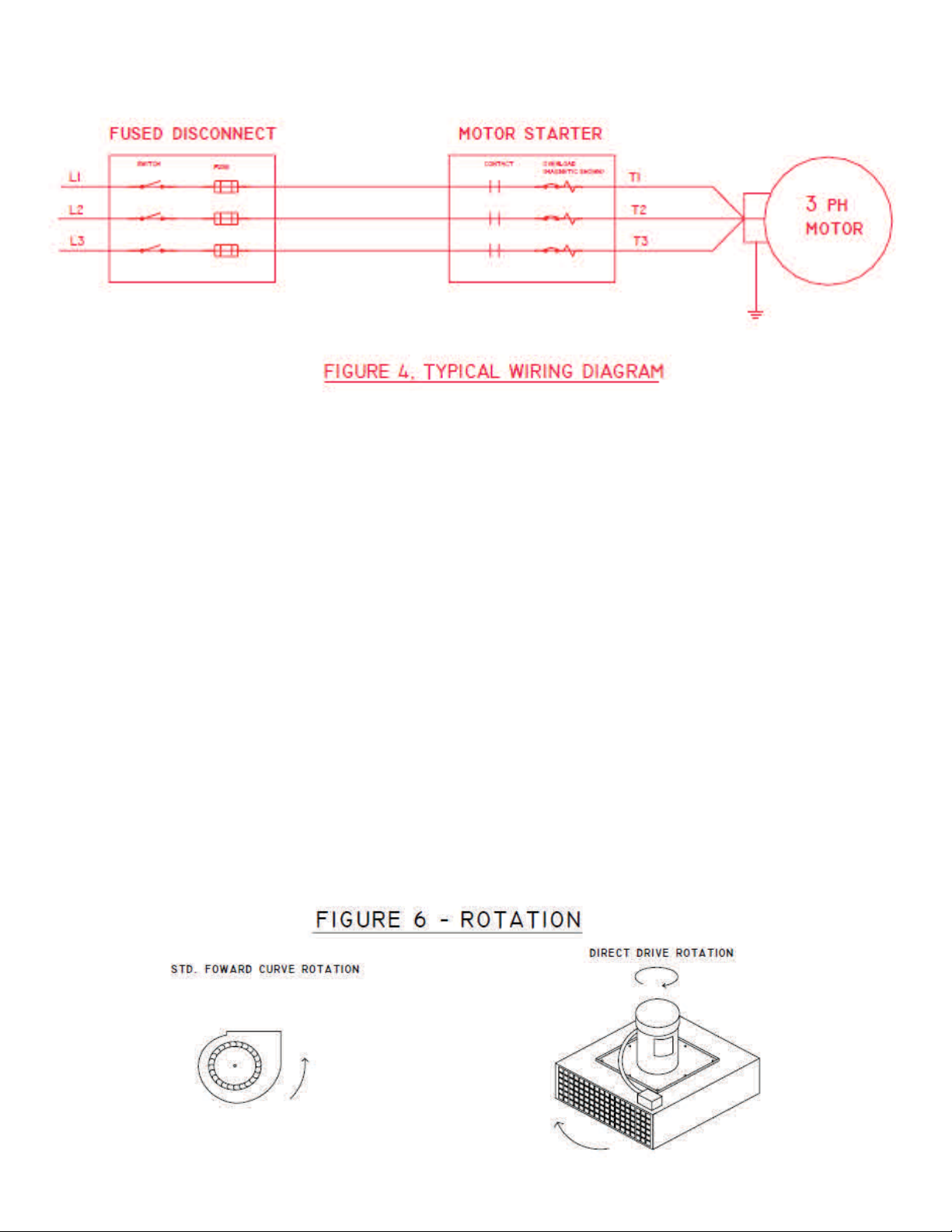
3 PHASE ELECTRICAL WIRING DIAGRAM
Standard 115v unit comes wired to a toggle switch with 15 ft cord, see figure 5 above. 230 V single phase units
are factory wired to a junction box on the side of the cabinet, switch not included. Additional wiring will be required
to get power to unit, which is not supplied with this product. Three phase units are wired to a junction box on the
motor, see figure 4 above.
Motor Starters, disconnects, wiring, overloads and thermal protection are NOT provided by the Manufacturer.
All Field wiring should be performed by a qualified electrician and must meet all local, NFPA and NEC codes.
Failure to install the proper electrical wiring, thermal protection, and controls will void the warranty.
ROTATION - On single phase units motor rotation can be reversed by switching the black and red leads in the
motor. Three phase motors can be reversed by switching leads L1 and L2. VERIFY rotation before operating the
air cleaner to avoid over amping the motor, voiding warranty.
After completion of the field wiring, turn the unit on to check for proper rotation. Rotation is marked on the side
of the blower housing for the standard forward curve blower. Optional direct drive BI blower wheels will rotate in
a clockwise direction when looking at the top of the motor, or the wheel should be spinning from right to left as
viewed through the exhaust grid. Backward rotation will result in a much lower air flow, louder noise, and will over
amp the motor. Check the motor nameplate before switching wires and reversing rotation, to ensure the unit is
operating at or below rated full load amp draw. Figure 6 illustrates how to identify the proper rotation.

9
Motor Mounting
Motor must be securely fastened to a rigid, flat surface to prevent vibration and minimize noise. For secure
mounting use high-quality bolts of the largest possible diameter.
Belt-drive sheaves must be in-line. Use a straight edge to check. Do not over-tighten belts.
Direct coupled installations require a careful check of shaft and coupling alignment, shaft offset and/or angular
misalignment should be less than .002”. Shim motor base as necessary. Do not depend on a flexible coupling to
compensate for misalignment.
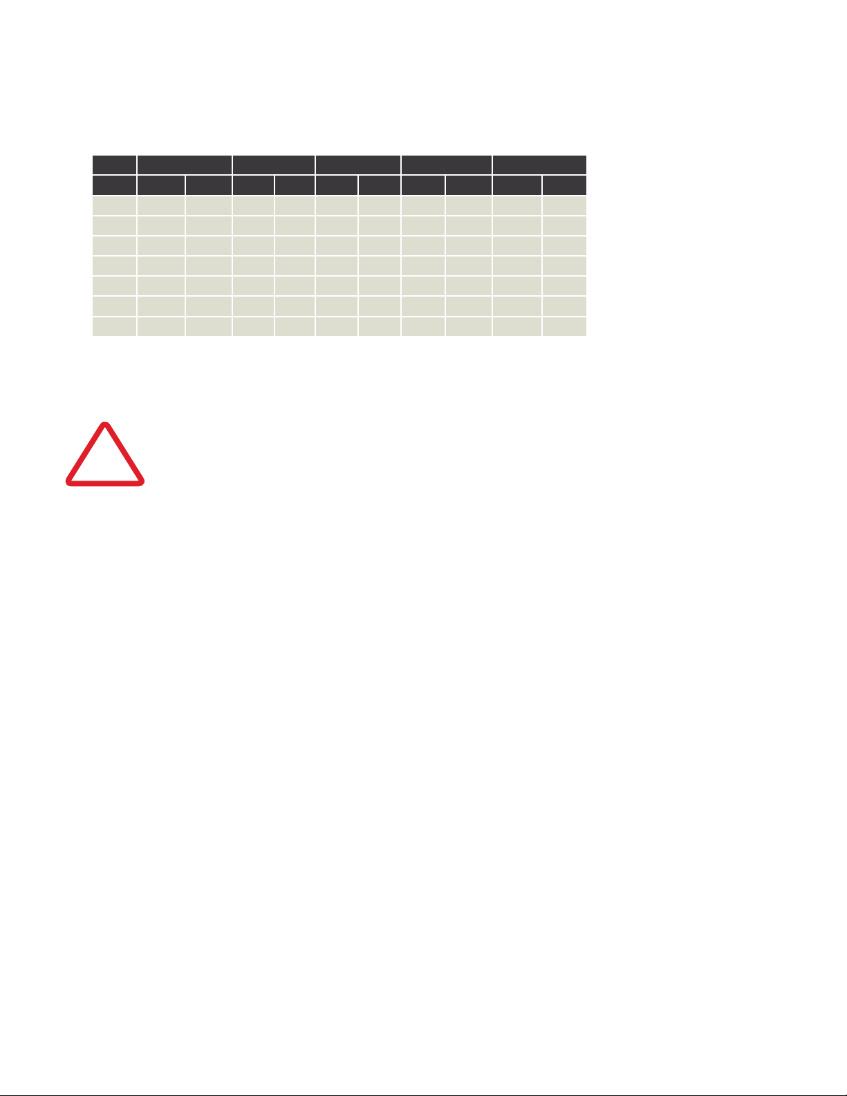
MOTOR 25 - 50 FEET 100 FEET 150 - 200 FEET
HP 200V 230V 460V 200V 230V 460V 200V 230V 460V
0.25 14 14(16)* 14(18)* 12 12 14(18)* 8 10 14(18)*
0.50 14 14(16)* 14(18)* 12 12 14(18)* 8 10 14(18)*
0.75 14 14(16)* 14(18)* 12 12 14(18)* 8 10 14(18)*
1.00 14 14(16)* 14(18)* 12 12 14(18)* 8 10 14(16)*
1.50 12 14 14(18)* 10 10 14(16)* 6 8 14
2.00 12 12 14(18)* 8 10 14(16)* 6 6 12
3.00 10 12 14(18)* 6 8 14 4 6 12
5.00 8 10 14(16)* 4 6 12 2 4 10
7.50 6 8 14 4 4 10 1 2 8
10 6 6 12 3 4 10 1/0 2/0 4
15 4 4 10 1 2 8 3/0 2/0 4
20 3 4 10 1/0 1 6 4/0 3/0 4
25 2 3 8 2/0 1/0 6 250kcmil 4/0 3
30 1 3 8 3/0 1/0 6 300kcmil 4/0 3
40 1/0 1 8 4/0 3/0 4 400kcmil 300kcmil 1
50 2/0 1 6 250kcmil 3/0 3 500kcmil 350kcmil 1
60 3/0 1/0 6 300kcmil 4/0 3 600kcmil 400kcmil 1/0
75 4/0 2/0 4 350kcmil 250kcmil 2 700kcmil 500kcmil 2/0
100 250kcmil 3/0 4 500kcmil 350kcmil 1 900kcmil 700kcmil 3/0
125 300kcmil 4/0 3 600kcmil 400kcmil 1/0 1250kcmil 800kcmil 4/0
150 350kcmil 250kcmil 2 700kcmil 500kcmil 2/0 1500kcmil 900kcmil 250kcmil
200 500kcmil 350kcmil 1/0 1250kcmil 800kcmil 4/0 1750kcmil 1250kcmil 350kcmil
250 600kcmil 400kcmil 2/0 1500kcmil 900kcmil 250kcmil 2000kcmil 1500kcmil 400kcmil
Table A - Minimum Wire Sizes for 3- Phase Motors
NOTE: kcmil denotes thousand circular mils. AWG sizes formerly given in MCM.
(*) Type S, SO, SJ, SJO, etc. flexible cable wire sizes. See NEC article 400 for ampacity.
10
Connecting Power to Motor
To connect motor for proper voltage and rotation, refer to the connection diagram on the nameplate
or inside the terminal/conduit box.
Table B - Minimum Wire Sizes for Single Phase Motors
Motor 25 Feet 50 Feet 100 Feet 150 Feet 200 Feet
HP 115V 230V 115V 230V 115V 230V 115V 230V 115V 230V
1.0 10 14(16)* 6 12 4 10 2 8 1 6
1.5 8 14 6 12 3 8 1 6 1/0 6
2.0 8 14 4 10 2 8 1/0 6 2/0 4
3.0 6 12 3 8 1/0 6 2/0 4 4/0 3
5.0 - 10 - 6 - 4 - 2 - 1
7.5 - 8 - 6 - 3 - 1 - 1/0
10.0 - 8 - 4 - 2 - 1/0 - 2/0
*Type S, SO, SJ, SJO, etc. Flexible cable wire sizes. See NEC Article 400 for ampacity.
NOTE: NEC Article 310-5 --- Minimum conductor size for general wiring at 115-440VAC is No. 14AWG. Above wire sizes based
on approximate 5% voltage drop during starting; copper conductors; and 75° C type THHW, THW, THWN, RH, RHW insulation,
etc. For aluminum wire, increase two wire size steps minimum. See NEC Article 310 for ampacities of aluminum conductors.
All aspects of the installation must conform to the requirements of the NEC, including Article 430 (Motor circuits and
Controllers), and all local codes. Wherever possible, each motor should be powered from a separate circuit of adequate capacity
to keep voltage drop to a minimum during starting and running. Increase wire size where motor is located a distance from the power
source. Wire size must be adequate to minimize voltage drop during starting and running. Refer to Tables A and B for suggested wire
sizes. Distances shown are one-way between source and motor. Portable cords, if used, should be as short as possible to minimize
voltage drop. Long or inadequately sized cords, especially on hard starting loads, can cause motor failure. All electrical connections in
system must be secure to prevent voltage drop and localized heating.
!WARNING
• Determine direction of rotation before connecting driven equipment to prevent damage.
• To prevent bearing damage, do not strike shafts with hammer or other tool.
• If the motor has been damp or wet, then have motor serviced by a qualified motor repair shop before operating.
Recommended Maintenance
Remove dirt accumulations in and around vent openings, by vacuuming. Dirt accumulations can cause motor overheating and a fire
hazard. Enclosed motors can be cleaned with an air jet; wear eye protection.
Periodically inspect the installation. Check for dirt accumulations; unusual noises or vibration; overheating; worn or loose couplings,
sheaves and belts; high motor current; poor wiring or overheated connections; loose mounting bolts or guards; and worn motor starter
contacts.
Dayton ball-bearing motors without lubrication provision do not require periodic relubrication. Where motor has provision for bearing
lubrication, lubricate as follows:
1. After stopping motor and disconnection power, thoroughly wipe the housing around both of the motor bearings, filler and drain plugs
(on TEFC) ratings, remove fan cover for access to plugs).
2. Remove filler and drain plugs and install a 1/8” pipe thread lube fitting in filler hole.
3. Using a low pressure grease gun, pump new grease into motor until it appears at the drain hole.
4. Run motor for several minutes to discharge excess grease. Shut motor OFF, replace filler and drain plugs, and reinstall fan cover.
See Table C for suggested regreasing intervals.

11
Motor HP at 1800 RPM Max.
Type of Service Under 50 50 to 100 Over 100
Infrequent operation or light duty in clean atmosphere 2 Years 2 Years 1 Years
8 to 16 hours per day in clean, relatively dry atmosphere 2 Years 1 ½ Years 1 Years
12 to 24 hours per day heavy duty use, or if moisture is present 1 Years 1 Years 6 Months
Heavy duty use in dirt, dusty locations; high ambients; moisture
laden atmosphere; constant vibration
4 Months 4 Months 3 Months
Table C - Suggested Regreasing Intervals
NOTE 1: Motors operating faster than 1800 RPM should be relubricated on a more frequent maintenance schedule. Use a reputable brand lithium or
synthetic-base grease intended for electric motor ball bearings. Recommended greases include: Standard Oil of California (Chevron) SRI#2, and Exxon
Corp. PolyRex-EM. Keep grease container clean and covered.
MOTOR TROUBLESHOOTING CHART
This chart suggests common answers to electric motor problems. The information is not all-inclusive and does
not necessarily apply in all cases. When unusual operating conditions, repetitive failures, or other problems
occur, consult an electric motor service firm for assistance.
Symptom Possible Cause(s) Corrective action
Motor fails to start 1. Blown fuses
2. Voltage too low at motor
terminals due to line drop
3. Overload in motor starter tripped
4. Overload (internal thermal
protector) tripped
5. Improper line connections
6. Motor may be overloaded
1. Replace with time-delay fuses.
Check for grounded winding
2. Consult local power company.
Increase wire size (refer to Tables A & B).
Check for poor connections
3. Check and reset overload relay in starter.
Check heater rating against motor
nameplate current rating
4. Check motor load. If motor has an automatic or manual
reset thermal protector, check if tripped
5. Check connections against diagram supplied
with motor
6. Reduce load or increase motor size
7. Repair or replace
Motor does not come up to
speed or takes too long to
accelerate
1. Not applied properly.
2. Voltage too low at motor terminals
3. Starting load too high.
4. Excess loading; tight belts
5. Defective motor
6. Inadequate starting torque.
High inertia load
1. Consult motor service firm for proper type.
Use larger motor.
2. Increase wire size (refer to Tables A & B). Check for
poor connections. Check for voltage
unbalance (3-Phase)
3. Check load motor is carrying at start.
4. Reduce load; adjust belts. Increase motor size.
5. Repair or replace
6. Replace with larger motor
Motor stalls during operation 1. Overloaded motor
2. Low motor voltage
1. Reduce load or increase motor size
2. Verify that nameplate voltage is maintained

12
Symptom Possible Cause(s) Corrective action
Motor vibrates or is
excessively noisy
1. Motor shaft misaligned
2. 3-phase motor running on single phase
3. High or unbalanced voltages
4. Worn, damaged, dirty or overloaded bearings
5. Defective winding. Bent or bowed shaft
6. Loose sheave or misaligned coupling
1. Realign
2. Check for open circuit, blown fuses or
unbalanced voltages
3. Check wiring connections. Consult local
power company
4. Replace bearings; check loading and alignment
5. Repair or replace
6. Tighten set screw(s); realign coupling
Motor overheats
while running
under load
1. Overloaded
2. Dirt blocking
3. If 3-Phase, one phase may be open
4. Unbalanced supply voltage
5. Faulty connection
6. High or low voltage
7. Defective motor
1. Reduce load; adjust belts. Increase motor size.
2. Clean motor
3. Check lines for open phase. Check voltage with
motor disconnected, one fuse may be blown.
4. Check for faulty connections. Voltage on all three
lines should be balanced within 1%. Balance single
phase loads.
5. Clean, tighten, or replace
6. Check voltage at motor, should not be more than
10% above or below rated
7. Repair or replace
Motor Troubleshooting (cont.)
Blower Operation
After electrical connections are completed, start motor briefly to determine the direction of wheel rotation. If
necessary to reverse the rotation, follow instructions given on the motor nameplate or terminal box cover. With air
system in full operation, and with all ducts attached and inspection door(s) closed, measure the current input to
the motor and compare with nameplate rating to determine if the motor is operating under safe load conditions.
Blower Maintenance
1. After electrical connections are completed, start motor briefly to determine the direction of wheel rotation.
If necessary to reverse. The rotation, follow instructions given on the motor nameplate or terminal box cover.
2. Follow motor manufacturer’s instructions for motor lubrication. Remove excess lubricant.
3. Follow Replacement Parts Manual for blower bearing lubrication.
4. Check wiring to make sure it is secure and well insulated.

13
Symptom Possible Cause(s) Corrective Action
Excessive noise and/or
vibration
1. Foreign object
2. Wheel rubbing on housing
3. Loose wheel or sheave on shaft
4. Motor or blower not secure
5. Belt(s) too loose/too tight
6. Worn belt(s)
7. Mismatched belt(s)
8. Loose or worn bearings
9. Bearing or drive alignment
10. Accumulation of material on wheel
11. Motor out of balance
12. Wheel out of balance
13. Sheaves eccentric or out of balance
1. Remove
2. Center the wheel
3. Tighten all set screws
4. Tighten Mounting
5. Adjust Tension
6. Replace
7. Replace
8. Replace
9. Realign
10. Clean
11. Replace
12. Replace or Rebalance
13. Replace
Insufficient air flow 1. Blower speed too low
2. Dampers or registers closed
3. Dirty or clogged filters
4. Leaks in duct work
5. Elbows, cabinet walls, or other obstructions
6. Belt slippage
1. Check for correct drives
2. Open
3. Clean or replace
4. Repair
5. Correct
6. Adjust or replace
Too much air flow 1. Blower speed too high
2. Filter(s) not in place
1. Check for correct drives
2. Install filter(s)
Unit fails to operate 1. Blown fuse or open circuit breaker
2. Broken fan belt
3. Defective motor and/or capacitor
1. Replace or reset
2. Replace
3. Replace
Motor overheats while running
under load
1. Blower speed too high or motor
horsepower too low
2. System static pressure too low
3. Shorted windings in motor
1. See Specifications for correct
drives and HP
2. Check static pressure and
correct system
3. Replace
BLOWER TROUBLESHOOTING CHART
START UP DATA: (write down for future reference)
MODEL NUMBER ______________________________ SERIAL NUMBER ______________________________________
HP ________________________ VOLTAGE ____________________ MFG. DATE ________________________________
VOLTAGE - L1 _________________________ L2 __________________________ L3 ______________________________
AMP DRAW - L1 ________________________ L2 _________________________ L3 ______________________________
OTHER NOTES:
____________________________________________________________________________________________________
____________________________________________________________________________________________________
PRESSURE GAUGE READING (AT START UP) ______________________________________________________________

14
NOTES

15
NOTES

16
NOTES

17
NOTES

18
TERMS AND CONDITIONS TO SALES ORDERS
1. INTERPRETATION
1.1. All references to “we” herein mean Diversitech Equipment and Sales (1984) Ltd.
1.2. All references to “you” herein mean:
(a) the “Customer” referred to herein and in the Sales Order joining these presents (such Sales Order together with any amendments, supplements
and additional agreements related thereto and all annexes and schedules in respect thereof, collectively the “Sales Order”); and
(b) any affiliates and any party related, whether directly or indirectly, to such “Customer”.
2. LIMITED WARRANTY AND LIABILITY
2.1. All units and equipment sold by us to you (collectively “Units”) pursuant to the Sales Order are warranted to be free from defects in material
for a period of 2 years from the date of purchase (the “Warranty Period”).
2.2. We will repair or replace, at our discretion, any defective parts that fail during the Warranty Period, returned to the manufacturer’s plant with
freight prepaid. This warranty is limited to replacement parts ONLY, subject to on-site or in- house evaluation of defective materials and does
not apply to any personal liability or property loss that occurs due to the use or installation of this equipment.
2.3. We expressly exclude all warranties whatsoever, other than those included in Section 2.1 hereof, express or implied, legal or conventional,
including, without limitation, any and all warranties of quality, merchantability and fitness for a particular purpose.
2.4. To the extent that any Units are integrated with any products, equipment, units, connections and/or systems of a third-party (“Third-Party Products”),
we hereby expressly exclude all of the following warranties, express or implied, namely:
(a) warranty against defects of any kind (latent or apparent), fitness for purpose, merchantability or functionality to the extent of any such Third-Party
Products; and
(b) any warranty against any defects or problems of any kind, whether latent or apparent, in respect of Units or a Third-Party Product, caused or arising
directly or indirectly as a result of the integration with or use of Units in connection with any Third-Party Product.
2.5. You hereby expressly waive and renounce to any and all claims against us relating to loss of profits, loss of business or goodwill, interruption
of business and all indirect, special, incidental or consequential damages of any kind whether arising from or in connection with the Sales
Order or from the use of Units, however caused, and whether in the nature of breach of obligations, breach of warranty, repudiation of
contract, tort, negligence (save in the event of gross negligence or intentional fault) or otherwise. Accordingly, save in the event of gross
negligence or intentional fault, we shall have no liability whatsoever towards you under this agreement for any losses or damages, direct or
indirect, consequential, exemplary, incidental or otherwise, regardless of whether we received advanced notice or were advised of the possibility of
such claim, loss or damage.
2.6. You are solely responsible for determining if Units fit your particular purpose and are suitable for your designated process, application, fitment,
tooling, set-up and uses(s).
3. FREIGHT CLAIMS
3.1. Shipments must be inspected by you upon arrival. All Units are sold ex-plant. Therefore, it is the receiver’s responsibility to file any freight
claims with the carrier for obvious or concealed damages. Damaged shipments must be refused at the time of receipt.
4. RETURN MATERIAL POLICY
4.1. Prior to the return of material, for whatever reason, a return merchandise authorization number (“RMA#”) is required from our customer service
department. This procedure is necessary for proper control and handling of returned materials. Call 1-800-361-3733 or email [email protected]
to obtain a RMA #. All material must be returned prepaid. Credit will be given for returns for warranty repair or replacement. Freight collect
shipments will not be accepted. It is the shipper’s responsibility to ensure that material being returned to us is adequately packaged for
shipment in order to prevent damages.

19
5. FEES AND CANCELLATION CHARGES
5.1. You will be responsible for any additional charges and fees not expressly included in the Sales Order, including, without limitation, any fees
or charges relating to installation, service calls, consulting, installation, customization, “right-sizing”, engineering, maintenance and/or repair. For
greater certainty, unless expressly provided in the Sales Order, we do not provide you with any form of service with respect to Units, including,
without limitation, installation, repair and maintenance services.
5.2. In the event that you:
(a) cancel the Sales Order at any time whatsoever, including, without limitation, prior to shipment;
(b) refuse to honour the Sales Order; or
(c) fail to take possession of any Units for any reason whatsoever,
you will be responsible for reimbursement to us of any and all costs, expenses and charges we have incurred to date.
5.3. In the event that:
(a) the Sales Order is for a customized product, including, without limitation, any custom engineered product; and
(b) an event set forth in Section 5.2 hereof occurs,
you will be responsible for payment of the entire amount of the Sales Order in addition to the reimbursement set forth in Section 5.2 hereof.
6. JURISDICTION AND ATTORNMENT
6.1. The interpretation, validity and enforcement of these presents and the Sales Order shall be subject to and governed by the laws of the Province of
Quebec and the laws of Canada applicable therein.
6.2. The parties hereto expressly submit, attorn and consent to the exclusive jurisdiction of the appropriate Court for the District of Montreal,
Province of Quebec, with respect to any controversy arising out of or relating to these presents and the Sales Order, or any supplement hereto
or to any transactions in connection therewith. To the extent permitted by applicable law, you irrevocably waive any objection (including any
claim of inconvenient forum) that you may now or hereafter have to the venue of any legal proceeding arising out of or relating to these presents
and the Sales Order in such courts.
7. GENERAL
7.1. If any provision of these presents or the Sales Order shall be held to be invalid, illegal or unenforceable, the validity, legality and enforceability
of the remaining provisions shall in no way be affected or impaired thereby.
7.2. These presents and the Sales Order shall be binding upon and inure to the benefit of the parties’ respective successors and assigns.
7.3. The parties hereto acknowledge that they have requested and are satisfied that the foregoing as well as the Sales Order and all notices, actions
and legal proceedings be drawn up in the English language. / Les parties à cette convention reconnaissent qu’elles ont exigé que ce qui
précède ainsi que le « Sales Order » et tous avis, actions ou procédures légales soient rédigés et exécutés en anglais et s’en déclarent satisfaites.

1200 55th Avenue
Montreal, Quebec H8T 3J8
Email: [email protected]
An Absolent
Group Company
For full product support, visit our website;
https://bit.ly/2q7UC4v
Scan above on mobile
Table of contents
Other DIVERSITECH Air Cleaner manuals


