DIYRE G BUS User manual

STEREO VCA COMPRESSOR
G BUS
Operation Manual


Welcome to the G Bus
Thank you for purchasing the G Bus. Now let’s get oriented.
The G Bus is a stereo bus compressor based on a classic console with several mods and updates. The front panel
is split up accordingly, with all of the original controls to the left of the dividing line, and all of the mods to the
right. The G Bus is a balanced, line-level piece of outboard equipment. It can be used as a line insert or send
during mixing, or after a mixer or mic preamp during tracking.
If you purchased your G Bus as a DIY kit, please visit the online assembly guide:
diy.re/gbus-manual
Quick Start Guide
This manual will help you get the most out of your G Bus by covering the features in-depth, but the G Bus is also
designed to be easy and intuitive to use, so if you’d rather play around than read, just follow the steps below:
• Plug the external power supply into the POWER INPUT jack and then into an outlet.
• Connect the XLR or ¼” TRS OUTPUT jacks to line inputs on your audio interface.
• Connect XLR or ¼” TRS line outputs from your audio interface to the left and right INPUT combo jacks.
• Start compressing!
1

Front Panel Description
THRESHOLD: Sets the gain level at which compression starts. The clockwise position is maximum (least sensitive),
turn counterclockwise to lower the threshold.
ATTACK: Sets the attack time of the compressor, measured in milliseconds.
RATIO: Sets the ratio of the compression between 2:1, 4:1, and 10:1 (depending on calibration).
RELEASE: Sets the release time of the compressor, measured in seconds.
MAKE-UP: Adds gain to make up for that lost when compressing. Counterclockwise is unity gain.
COMPRESSOR: Engages compression. In the OUT position the signal still runs through the audio path of the
compressor, including the XFMR stage if it is engaged.
FILTER: Engages the sidechain lters or external sidechain input. In position 1 (counterclockwise) the lters are
OFF and have no eect on the signal. Positions 2-4 are high-pass lters, with the corner frequencies indicated
in hertz. Position 5 is a shelf lter that deemphasizes low frequencies and emphasizes high. Position 6 is for the
external sidechain input.
DRY/WET: Blends the dry signal with the compressed signal when MIX is engaged.
MIX: Engages the DRY/WET control for parallel compression. In the OUT position the mix circuitry is completely
disabled and has no eect.
MONO SC: Sums the left and right signals at the start of the sidechain detection circuit. The default, OUT,
position is how the original console worked.
XFMR: Switches between a clean, IC-based output and a saturated transformer output. The default, OUT,
position is closest to the original.
DRIVE: Switches between three drive settings. These increase the gain going to the transformer and attenuate
after it to maintain unity gain while increasing saturation.
2

Rear Panel Description
POWER INPUT: DC power input from the external power supply.
THRU: Used for powering multiple DIYRE units from a single, external power supply. Compatible units include
the G BUS, COLOUR DUO, and PR502. To daisy chain, run a 5-pin XLR cable from the THRU jack of the rst unit
to the POWER INPUT jack of the unit to be powered. Up to 4 units can be powered by a single external power
supply.
INPUT x2: Balanced, line-level XLR/TRS combo input.
OUTPUT x2: Parallel XLR and ¼” TRS output jacks. Both are balanced and carry the same signal. Both can be
used at the same time to send the output to two devices at once.
EXT SC INPUT: Unbalanced, XLR/TRS combo input for external sidechain control. Set the FILTER switch to
EXT SC and feed a separate signal to this input.
3

Block Diagram
Audio enters the G Bus through the input amplier, which converts the signal from balanced to unbalanced. It
then splits to three places: the mix circuit, the rest of the audio path, and the sidechain (SC).
In the mix circuit, the output from the balanced input is summed with the output from the audio VCA. The
following MIX switch selects between the output from the VCA (default) and the output of the mix circuit.
In the audio circuit, the signal passes through the unity gain trim and into the audio VCA, which controls the level
based on the control voltage (CV) from the SC. It then goes to the mix circuit and switch.
In the sidechain, the signal passes through the MONO SC switch, where it is either summed to mono or left stereo.
It then passes through the lters and into the SC VCA. This VCA acts as a mirror of the audio VCA, essentially
creating feedback behavior where the sidechain “sees” the signal after it is compressed. The signal is then
converted to DC and manipulated by the ratio, attack, and release sections. The signal that emerges is the CV. It is
sent to three places: the meter, the SC VCA (feedback), and the audio VCA’s control port. The THRESHOLD control
sets the sensitivity of the compressor by controlling the gain of the SC VCA. The MAKE-UP control provides extra
gain at the audio VCA.
Returning to the audio path after the MIX switch, the signal goes to the IC (default) and XFMR outputs in parallel.
The XFMR switch selects which output will go to the balanced output jacks.
4

5
Specications
Line Input
Impedance: 10kΩ
Max Input Level: 27.5dBu
Line Output
Output Impedance: 100Ω
Max Output Level: +22dBu
General
Make-up Gain: 25dB
Frequency Response: ±0.2dB 20Hz to 20kHz rel. 1kHz
Noise: -85dBu, 20Hz to 20kHz, input terminated with 600 Ohms
Power Rails: ±16vDC, ±12vDC, +48vDC
Wall Power: 100-240VAC, ~50/60Hz 2.5A
Dimensions
Width: 19”
Height: 1.72”
Depth: 8.38”

G Bus Recall Sheet
Print your own at diy.re/recall
Date: Artist: Project: Bus:Track:

7
Replacement Parts
Below is a list of o-the-shelf components (other than custom parts) should you need a replacement down the
road. For parts listed ‘DIYRE’ please contact us for replacements at diy.re/contact
REFERENCE DESIGNATOR VALUE MAN. PART NUMBER SOURCE
Front panel screws 6-32, 1/4" at head screw 96640A110 McMaster-Carr
IC1, IC6, IC7 LF347 quad opamp LF347N TI
IC2-IC5 5532 dual opamp NE5532P TI
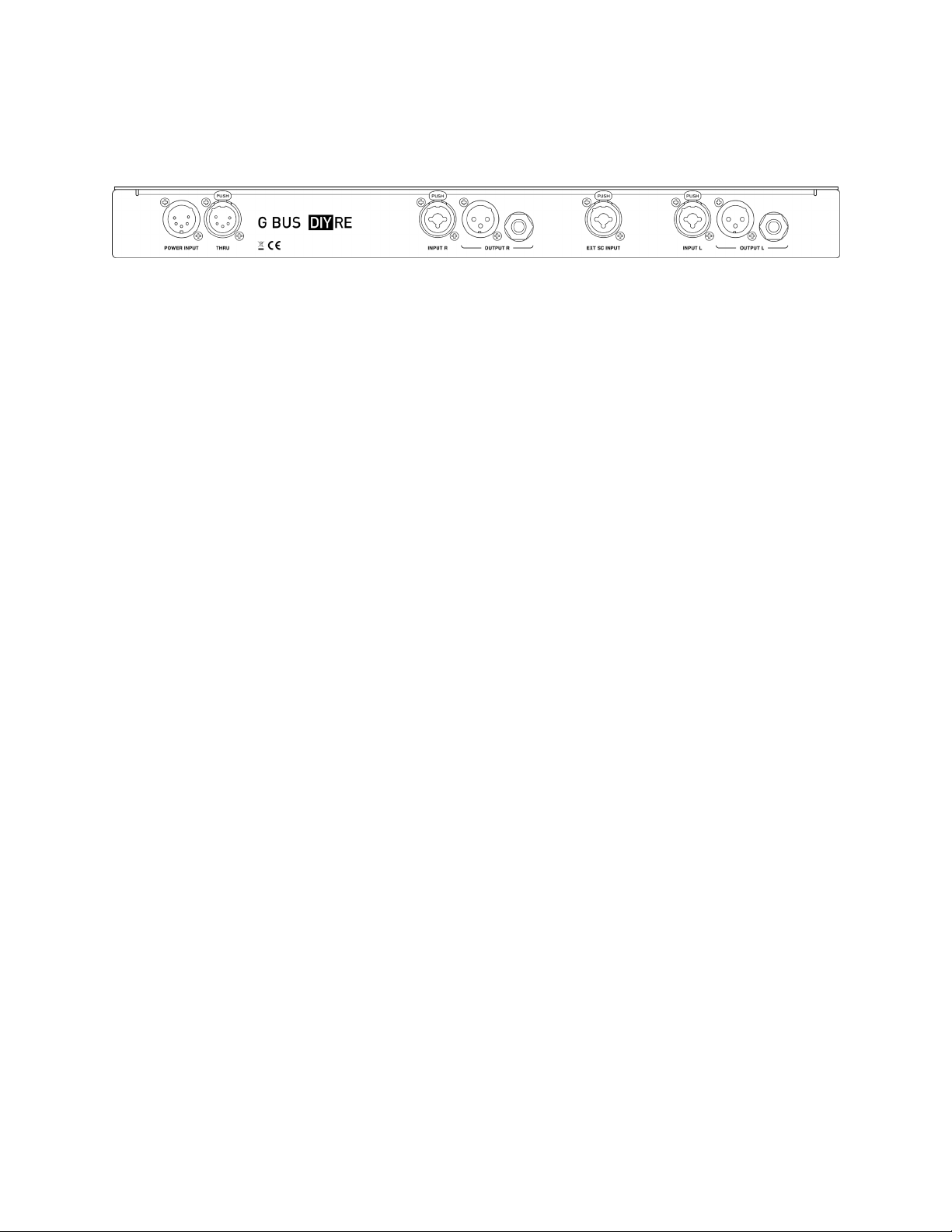
J1 5-pin Power thru jack AC5FAH-AU-B APC
J2 5-pin Power input jack AC5MAH-AU-B Amphenol
J3 TRS output jack PJ-644D Daier
J4 3-pin XLR output jack NC3MAAH-1 Amphenol
J5, J6 3-pin XLR/TRS combo input jack NCJ6FA-H Neutrik
Lid/bracket screws 4-40, 3/16" at head undercut
screw
96640A052 McMaster-Carr
Meter 1mA linear scale 100uA/dB Custom DIYRE
“IN” switch DPDT switch, KD2-style Custom DIYRE
PB switch board mounting 4-40 nut 96537A120 McMaster-Carr
PB switch board mounting 4-40, 3/8" pan head screw 91249A108 McMaster-Carr
PB switch board mounting 4-40, 5/32" stando 93330A495 McMaster-Carr
PCB stando screws 4-40, 1/4" pan head screw 91249A105 McMaster-Carr
RA1, RA2 10k resistor array 4608X-102-103LF Bourns
SW1_CB-SW3_CB, SW5_CB 2-pole, 6-throw rotary switch Custom DIYRE
SW6_CB-SW8_CB DPDT pushbutton switch TL2201EEZB E-Switch
SW6_CB-SW8_CB Pushbutton switch cap PB 07/51/000 Sifam
SW9_CB 4-pole, 3-throw rotary switch Custom DIYRE
Transformer screws 4-40, 7/8" pan head screw 91772A114 McMaster-Carr
U1 7812 +12v regulator MC78L12ACPR TI
U2 7912 -12v regulator MC79L12ACLPR TI
U3-U6 DPDT 24V relay J104D2C24VDC.20S CIT
VCA1A/VCA2 PCB with 2181C, SMD Custom DIYRE
VR1_CB-VR3_CB Control knob DR151-006_180gray Sifam
VR1_CB-VR3_CB Control knob insert C151 gray Sifam
VR1_CB, VR2_CB B50K Custom DIYRE
VR3_CB B10K Custom DIYRE
X1 Line out transformer 2523 DIYRE
XLR screws #4, 3/8" plastic thread forming
screw
99461A120 McMaster-Carr

8

9
Safety
As with any electronic device, operating the G Bus safely requires some common sense and respect for the dangers of electrical
power. Treat your G Bus like a hair dryer. Don’t turn it on when it’s wet, only clean it with a dry cloth, and if you spill a liquid on
it unplug it immediately and don’t turn it back on until it’s been repaired by a tech.
Warranty
DIY Recording Equipment, LLC (DIYRE) warrants this product to be free from defects and will remedy any such defects free
of charge according to the terms of this warranty. DIYRE will repair or replace at its option any defective component(s) of this
product, excluding the coating and labeling for a period of two (2) years from the original date of purchase. In the event that
a particular product is no longer available, DIYRE will replace the product with a similar product of equal or greater value. To
make a request or claim under this limited warranty, return your G Bus prepaid to DIYRE with a copy of the original invoice. This
limited warranty will not apply if the product has been damaged due to abuse, misuse, misapplication, accident, or as a result
of service or modication by the user. This warranty applies only to units assembled by DIYRE, not DIY kits.
Disclaimer
The G Bus is an electronic device intended to be used with properly grounded ampliers and other audio devices. Connecting
the G Bus to mis-wired or faulty equipment may result in electric shock. The user is responsible for using the G Bus safely and
DIYRE disclaims liability for any damage or injury resulting from the use of this product. If you are not completely sure of the
safety of connecting the G Bus to a certain piece of equipment, consult a qualied technician before proceeding.
Attribution 4.0 International, DIY Recording Equipment, LLC, 2022

Table of contents