DKS AQUATRACE-IV User manual

1
Radeberger Str. 21; 01900 Großröhrsdorf
Tel. / Fax. 0049 35952- 429465 /- 429457
E-Mail: info@dks-engineering.de; www.dks-engineering.de
➢MANUAL
AQUATRACE®-IV
TRACE MOISTURE ANALYZERS FOR GASES
0-2000ppmV
Portable devices (optional with battery)
Wall mounted device (IP65)
19 inch Rack (up to 4 channels)
Measuring cells in different variants available:
Stainless steel | PVDF | glass or ceramic
sensor

2
Radeberger Str. 21; 01900 Großröhrsdorf
Tel. / Fax. 0049 35952- 429465 /- 429457
E-Mail: info@dks-engineering.de; www.dks-engineering.de
INDEX
1. INTRODUCTION ................................................................................................................................................... 3
2. THE BASIC INSTRUMENT STRUCTURE OF THE AQUATRACE® ANALYZER ............................................................. 3
3. MEASURING PRINCIPLE ....................................................................................................................................... 4
4. MEASUREMENT SETUP........................................................................................................................................ 4
5. REQUIREMENTS FOR TROUBLE-FREE OPERATION OF THE MEASURING DEVICE................................................. 6
6. EXPLANATION OF THE MENU STRUCTURE AND EXECUTION OF THE MEASUREMENT........................................ 7
7. SPECIAL FUNCTIONS .......................................................................................................................................... 19
7.1 VIRTUAL NETWORK COMPUTING.................................................................................................................... 19
7.2. ULTRA VNC ON A WINDOWS PC..................................................................................................................... 21
7.3. INDIVIDUAL ADJUSTMENT OF THE CHARACTERISTIC CURVE.......................................................................... 22
8. PLUG ASSIGNMENT ( APPLIES TO EACHS CHANNEL ) ........................................................................................ 26
8.1 MEASURING CELL –DEVICE............................................................................................................................. 26
8.2 ANALOG OUTPUT 4 –20 MA SCALABLE .......................................................................................................... 26
8.3 RELAY OUTPUTS 1 + 2...................................................................................................................................... 27
8.4 RELAY OUTPUTS 3 + 4...................................................................................................................................... 27
9. SATUS OUTPUT ( ONCE PER DEVICE ) ................................................................................................................ 27
10. FAQ.................................................................................................................................................................. 28
10.1 WHAT DETERMINES THE RESPONSE TIME OF THE SENSOR TO A HUMIDITY EVENT? ................................... 28
10.2 HOW DOES THE SENSOR BEHAVE IN CASE OF WET DECREASE? ................................................................... 28
10.3 WHAT DO THE ERROR MESSAGES ON THE DISPLAY MEAN? ......................................................................... 28
11. DESCRIPTION OF THE CONTROLS .................................................................................................................... 29
12. TECHNICAL DATA............................................................................................................................................. 31
13. SAMPLING SYSTEM.......................................................................................................................................... 32

3
Radeberger Str. 21; 01900 Großröhrsdorf
Tel. / Fax. 0049 35952- 429465 /- 429457
E-Mail: info@dks-engineering.de; www.dks-engineering.de
1. Introduction
The AQUATRACE IV devices are a further development of our proven series of moisture trace
measuring instruments, which work on the basis of P2O5sensors and can be used to determine
the humidity in all gases (except NH3) in the coarse and fine ppmVrange. The measuring
system consists of an electronic measuring instrument and a separately installed measuring
cell that can be integrated into a gas handling system. The measuring instruments are available
as:
1. Laboratory device (portable version) - Model T
2. Laboratory device with battery (portable version) - Model A
3. Industrial device in 19" rack ( 3 U ) or - Model R
4. Wall Unit (IP65) - Model W
2. The basic instrument structure of the AQUATRACE® Analyzer
2. Depending on the version, the devices can process up to a maximum of 4 independent
channels (humidity sensors)
3. The display is designed as a touch screen and thus dispenses with susceptible controls
4. The 7" graphic display with a resolution of 800 x480 pixels shows the time-dependent
course of the measured values for one or all integrated channels.
5. The run-in process after recoating is represented with logarithmic scaling. After falling
below the upper measured value scaled for the channel, the display automatically
switches to linear scaling.
6. The re-coating of the sensor is menu-guided.
7. The menu navigation is largely self-explanatory
8. Optionally, the display can be set in ppmVor Dp in°C. The conversion is done
automatically using the Magnus formula
9. The user language is adjustable. It can be selected from 9 languages
10. Production according to ISO 9001
11. The device design follows the current NAMUR recommendations, according to which
status signals for failure, limit exceedance, maintenance requirements, device in
maintenance
should be provided as potential-free relays.
12. An automatable sensor test enables the self-monitoring of the
Device
13. All changes and settings are secured by password protection on several levels
(operator, engineer, administrator)
14. Calibration and adjustment with separately available dongle necessary
15. The analog output (4....20 mA) is freely scalable
16. The device records all measured values and changes to the device per channel in the
background and has a USB interface via which all data can be read out as a logbook in
CSV format.

4
Radeberger Str. 21; 01900 Großröhrsdorf
Tel. / Fax. 0049 35952- 429465 /- 429457
E-Mail: info@dks-engineering.de; www.dks-engineering.de
3. Measuring principle
The principle of recording the moisture content of gases is based on the electrolysis of water,
which is adsorbed by phosphorus pentoxide. In the AQUATRACE® IV, the sensor coated with
H3PO4 is surrounded by a precisely defined amount of gas. The cell parameters and the flow
velocity are coordinated in such a way that the acid always absorbs a constant proportion of
the gas moisture and this proportion is electrolyzed in the same unit of time. The consequence
of this is the setting of a dynamic equilibrium in which the flowing current is directly
proportional to the moisture content.
4. Measurement setup
The measuring cells consist of the sensor in the form of a cylindrical carrier, optionally of:
-ZrO2 with an interdigital structure of Pt layers, or of glass with bifilar wound Pt electrodes,
and the sensor housing, which
is available in rust-free stainless steel ( V4A ) or in PVDF,
This means that almost all requirements regarding corrosion resistance can be met.

5
Radeberger Str. 21; 01900 Großröhrsdorf
Tel. / Fax. 0049 35952- 429465 /- 429457
E-Mail: info@dks-engineering.de; www.dks-engineering.de
The sensors are coated with phosphoric acid. In the operating menu, the cleaning and
recoating of the sensor with H3PO4approx. 40% ( semi-concentrated ) is described. This work
step is of particular importance, as the trouble-free functioning of the P2O5sensor depends
on the careful execution.
The handling of the sensor is simple, but requires a certain amount of practice:
1. In principle, when cleaning and recoating, care must be taken to ensure that no
moisture reaches the socket. This means that after thorough cleaning of the sensor
under running water, it must be dried thoroughly with lint-free cloth (paper).
2. When coating the sensor, make sure that the sensor tip is always slightly tilted
downwards.
3. Only 1 –2 drops of electrolyte (glass sensor up to 3 drops) should always be distributed
on the "active" sensor surface (slight turning; possibly distribute with brush).
4. To avoid "splashing" of the electrolyte solution in the sensor housing, the strong
formation of bubbles on the sensor should have subsided before it is inserted into
the chamber.
Please note!
Moisture residues on the housing wall are very slowly degraded by the passing dry gas,
which leads to falsified (increased) measured values over a longer period of time.
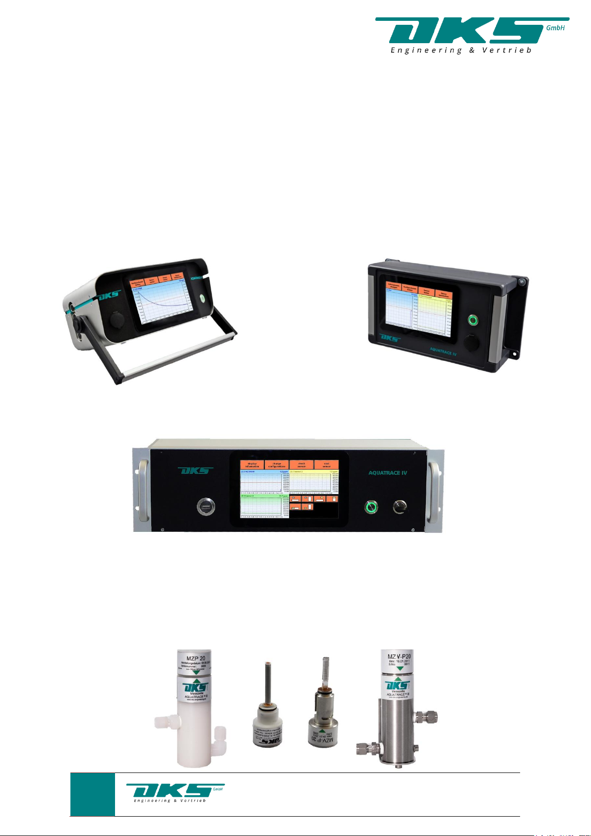
When operating the measuring cell, a constant gas flow must always be ensured. The flow
rate has an influence on the response time after humidity change but also on the absolute
value, since a corresponding calibration curve is firmly stored in the evaluation electronics.
Measuring cells for flow rates of 20 Nl/h or 100 Nl/h are available. The evaluation unit
automatically detects which of the two cell types is connected. For safety reasons, the cells
are designed for a pressure of up to 10 bar, and are usually sealed via a Viton-O-ring.
Normally, the measurement is carried out under low overpressure (20 - 100mbar). Higher
pressures must be reduced beforehand with a pressure regulator or throttle dosing valve.
A prerequisite for reliable measurement results is the acquisition and consistency of the flow
velocity. We recommend a needle valve at the input and a rotameter at the output of the
measuring cell. All components used in front of the measuring cell should have a leakage rate
of morethan 10-4 mbar l/s.
Behind the cell, the measured gas must flow off without pressure, with at least 1m pipe length
provided for the exhaust pipe. With shorter pipes, it can easily lead to re-diffusion of moisture
from the environment (partial pressure gradient).
The pipelines for measurement should always be in V2A or better. For particularly aggressive
gases such as chlorine, PTFE pipe is to be used. Other plastic materials may cause a strong
diffusion of moisture into the gas.

6
Radeberger Str. 21; 01900 Großröhrsdorf
Tel. / Fax. 0049 35952- 429465 /- 429457
E-Mail: info@dks-engineering.de; www.dks-engineering.de
5. Requirements for trouble-free operation of the measuring device
In principle, care must be taken to ensure that the gas supply routes to the measuring cell are
as short as possible. Keep in mind that the water molecules are always inclined to attach to
the "inner surfaces".
This effect is more pronounced the larger these surfaces are, this means the greater the
roughness of the pipe wall and the higher the moisture content of the gas. This is a special
feature of the behavior of the water molecules and not a property of the measuring system.
Electropolished surfaces or glass-coated surfaces minimize these effects. Set enough time for
the "flushing of the measuring device" after the initial commissioning and openings, e.g. after
service work.
The measuring cable between the cell and the evaluation device is 2.0 m long as standard.
However, distances of up to 150 m between the measuring point and the evaluation device
are possible. Please contact us about the dimensioning of the cable.
For measurements in explosive gases, an intrinsically safe design of the measurement
arrangement is required. Please contact us about the specific device design required for this!
Before the start of the measurement, the entire system must be checked for tightness and
thoroughly rinsed. Depending on the cleanliness of the plant components and the length of
the gas supply pipes, this process can take several hours, as the moisture components
adsorbed on the inner surfaces must be degraded.
This preparation phase is complete when the value displayed on the device does not change
within about 30 minutes.

7
Radeberger Str. 21; 01900 Großröhrsdorf
Tel. / Fax. 0049 35952- 429465 /- 429457
E-Mail: info@dks-engineering.de; www.dks-engineering.de
6. Explanation of the menu structure and execution of the measurement
After the system startup has been done, the system configuration logs in, where you can select
the desired language. The entire operation can then be carried out in this language.
Configuration menu item
• Display in ppmVor Dp in°C
• Language selection
• Nutzerverwaltung
• Channel management
• Data export (value range, channel, etc.)
• Date, time
• „stamp“ (z.B.: Messstellenbezeichnung; Gasbezeichnung ect.)
• Define name of the channels
• Scaling of the display area
• Alarm/ Limit-configuration
• Setting of the automatic sensor test (per channel)
• Analog output scaling (per channel)

8
Radeberger Str. 21; 01900 Großröhrsdorf
Tel. / Fax. 0049 35952- 429465 /- 429457
E-Mail: info@dks-engineering.de; www.dks-engineering.de
View information:
-Type
-Device number
-Delivery date
-Version
-Firmware version
-Date of last data output
In the menu item "Users" any number of users with different access authorizations can be
created.
4 operator levels are provided for these authorizations:
0. Free access (access without PIN code, or dongle)
1. Plant personnel - PIN - for channel switching; sensor test; sensor maintenance; Coating
2. Engineer - PIN - change for device configuration; Read data; Read device status
3. Service - protected interface - change soft/firmware; Diagnosis
For each available channel, the intended parameters can be defined or selected.

9
Radeberger Str. 21; 01900 Großröhrsdorf
Tel. / Fax. 0049 35952- 429465 /- 429457
E-Mail: info@dks-engineering.de; www.dks-engineering.de
The recorded measurement data can be read out via the "logbook" on a USB stick and made
available as a date-based, daily *.csv file.
Basic menu structure with header for function keys

10
Radeberger Str. 21; 01900 Großröhrsdorf
Tel. / Fax. 0049 35952- 429465 /- 429457
E-Mail: info@dks-engineering.de; www.dks-engineering.de
The arrangement of the channel representation can be changed as desired:
By touching a channel field, it appears in the foreground:
The visible range of the timeline is adjustable and zoomable by touch:

11
Radeberger Str. 21; 01900 Großröhrsdorf
Tel. / Fax. 0049 35952- 429465 /- 429457
E-Mail: info@dks-engineering.de; www.dks-engineering.de
Representation of an "infeed operation" with logarithmic scaling:
As long as the adjustable limit value is exceeded, the display flashes red.
Regular curve after falling below the limit value. (here 55.0 ppm) :

12
Radeberger Str. 21; 01900 Großröhrsdorf
Tel. / Fax. 0049 35952- 429465 /- 429457
E-Mail: info@dks-engineering.de; www.dks-engineering.de
When the visible curve value on the left edge of the image has reached the scaled maximum
value, the scaling switches back to linear division:
A sensor test is carried out to check the measuring cell. By touch, the respective sensor is
selected:

13
Radeberger Str. 21; 01900 Großröhrsdorf
Tel. / Fax. 0049 35952- 429465 /- 429457
E-Mail: info@dks-engineering.de; www.dks-engineering.de
For the sensor test, the input of the PIN (engineer or operator level)
required. (see menu item "Users" if this is specified.) :
After confirming with "Enter" you will be taken to the test menu.
You can now start the test ( yes ), or leave the menu again ( no ):

14
Radeberger Str. 21; 01900 Großröhrsdorf
Tel. / Fax. 0049 35952- 429465 /- 429457
E-Mail: info@dks-engineering.de; www.dks-engineering.de
When the test is started, it runs automatically and the time course
can be tracked.
In the meantime, the analog output is switched to "sample and hold":
The test result is displayed and, as in the example shown, again with "ok"
switched to measurement mode:

15
Radeberger Str. 21; 01900 Großröhrsdorf
Tel. / Fax. 0049 35952- 429465 /- 429457
E-Mail: info@dks-engineering.de; www.dks-engineering.de
If the test is negative, the relay "maintenance requirement" is activated and it can be decided
whether to switch to the coating mode ( yes ), or to measure further ( no ). In this case, the
service icon remains active:
If confirmed with "yes", the operator receives an indication of possible dangers. At the same
time, the voltage on the sensor is switched off, the analog output switches to "sample and
hold", the last measured value is displayed on the display (here 50.6 ppm) and the relay
"Maintenance" is activated. The sensor is cleaned and the success is checked with "ok".

16
Radeberger Str. 21; 01900 Großröhrsdorf
Tel. / Fax. 0049 35952- 429465 /- 429457
E-Mail: info@dks-engineering.de; www.dks-engineering.de
If the cleaning was not successful; i.e. the "electric zero point" has not been reached, the
process must be repeated.
If the cleaning result is positive (< 0.1 ppm), the voltage is restored again
switched on and the sensor can be coated with phosphoric acid

17
Radeberger Str. 21; 01900 Großröhrsdorf
Tel. / Fax. 0049 35952- 429465 /- 429457
E-Mail: info@dks-engineering.de; www.dks-engineering.de
Please note: Insert the sensor into the reaction chamber only after the bubble formation has
subsided. With the "ok" confirmation, the inlet curve appears in the display in logarithmic
representation. The relay "Maintenance" is only deactivated after falling below the limit and
releases the analog output again ("sample and hold" is switched off).
If basic maintenance work has to be carried out on the measuring system, you can select "Wait
sensor" via the main menu and specify for which channel the maintenance is to be carried out.
(see NAMUR recommendations; Function "Key Switch")
The following image will then appear with the selection option:

18
Radeberger Str. 21; 01900 Großröhrsdorf
Tel. / Fax. 0049 35952- 429465 /- 429457
E-Mail: info@dks-engineering.de; www.dks-engineering.de
If the maintenance has been confirmed with "yes" for the selected channel, the icon for this
channel appears on the display for the duration of the maintenance:
After completion of the work, the maintenance mode can be deactivated again via the button
"maintenance sensor":

19
Radeberger Str. 21; 01900 Großröhrsdorf
Tel. / Fax. 0049 35952- 429465 /- 429457
E-Mail: info@dks-engineering.de; www.dks-engineering.de
7. Special functions
All measuring instruments, except the AQUATRACE® IV-A have a digital Ethernet interface
with Modbus TCP protocol.
In the AQUATRACE IV, the following functions are possible via this interface:
1. Modbus TCP (direct, up-to-date data transfer from PLS)
2. Remote control of an AQUATRACE IV device via VNC
3. FTP ( File Transfer )
VNC implements the Remote Framebuffer Protocol and is platform-independent
7.1 Virtual Network Computing
By using of the digital interface with Modbus TCP protocol it is possible to use VNC.
For this purpose, the IP address of the AQUATRACE® IV must be adapted according to the
conditions at the place of use.
When the system is fully loaded, please press "change configuration":
Other manuals for AQUATRACE-IV
1
Table of contents
Other DKS Measuring Instrument manuals
Popular Measuring Instrument manuals by other brands

BD
BD LSRII Workbook

MR
MR MESSKO PQ96 operating instructions

Neptune Technology
Neptune Technology Pressure Spy Quick install guide

Endress+Hauser
Endress+Hauser Deltabar S FMD76 operating instructions

Agilent Technologies
Agilent Technologies U1731B User's and service guide

Semtech
Semtech IOT8EUSBREF-1 user guide