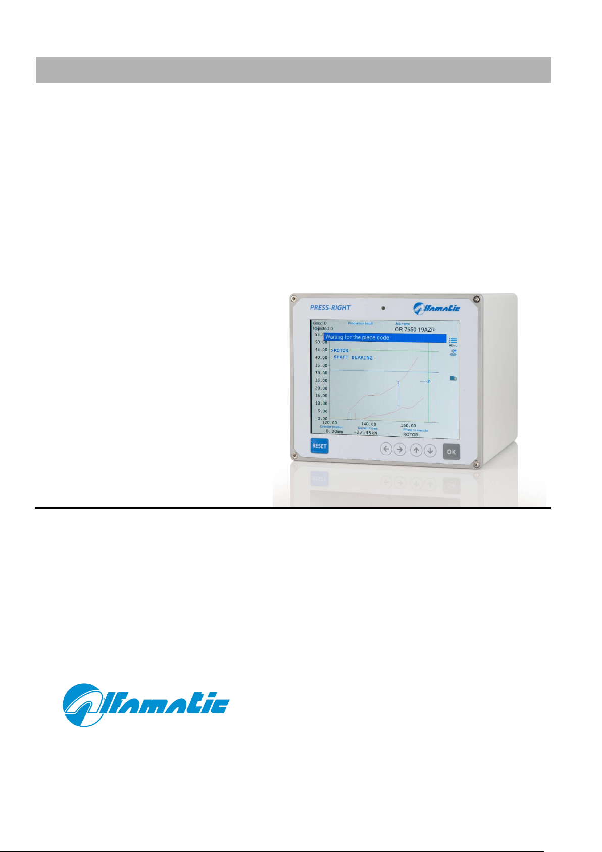
ALFAMATIC Press-Right User manual

U S E R M A N U A L
PRESS-RIGHT
FOR PNEUMATIC AND
HYDRAULIC PRESSES
•User manual

2 PRESS-RIGHT

PRESS-RIGHT 3
1General information .............................................................................................. 5
1.1 Notes on control theory.............................................................................................5
1.2 Control of position-force curve...................................................................................5
1.3 Absolute and relative positions..................................................................................6
2Installation of Press-Right..................................................................................... 8
3Getting started...................................................................................................... 9
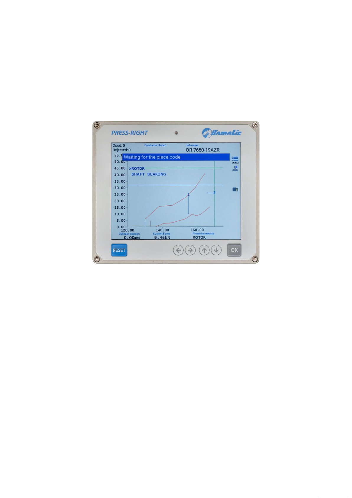
3.1 The keyboard of Press-Right.....................................................................................9
3.2 First approach...........................................................................................................9
3.3 Setting the display...................................................................................................10
3.4 The main menu.......................................................................................................10
4The jobs.............................................................................................................. 12
4.1 Creating a new job..................................................................................................12
4.2 Select a job.............................................................................................................12
4.3 Modifying the Job Name..........................................................................................12
4.4 Selecting a job using a bar code .............................................................................12
4.5 Job selection via tools recognition...........................................................................13
4.6 Selecting a Job via Fieldbus....................................................................................13
4.7 Changing Job Codes...............................................................................................14
4.8 Copy a job...............................................................................................................14
4.9 Deleting a job..........................................................................................................14
4.10 Modify a job.............................................................................................................14
4.11 Job counters ...........................................................................................................14
4.12 The graph ...............................................................................................................15
4.13 Options and rejected management .........................................................................15
4.14 Phase management................................................................................................16
4.15 Channel management.............................................................................................16
4.16 Functionality verification procedure.........................................................................16
4.17 Management of supplementary control signals .......................................................17
5Parameters......................................................................................................... 19
5.1 Stop values.............................................................................................................19
5.2 Control limits...........................................................................................................21
5.3 How to setup job.....................................................................................................22
5.4 Check points...........................................................................................................23
5.5 Job Options.............................................................................................................23
5.6 Job accessories......................................................................................................24
6The tolerance range............................................................................................ 25
6.1 Create the tolerance range......................................................................................25
6.2 Modify the tolerance range......................................................................................25
6.3 Detete the tolerance range......................................................................................26
7Rejected parts..................................................................................................... 27
7.1 The causes of the rejected......................................................................................27
7.2 Management of reject .............................................................................................28
8Measured values ................................................................................................ 30
8.1 The window of measured values.............................................................................30
8.2 Analysis cursor........................................................................................................30
9The tools menu................................................................................................... 31
9.1 Display options........................................................................................................31
10 Special configurations......................................................................................... 32
10.1 Transducer of additional force.................................................................................32
10.2 Tool recognition ......................................................................................................32

4 PRESS-RIGHT
11 Password............................................................................................................ 34
12 Field bus............................................................................................................. 35
12.1 Organization............................................................................................................35
12.2 Status e Control......................................................................................................35
12.3 Modbus/TCP...........................................................................................................36
12.4 PROFINET e EtherNet/IP........................................................................................36
12.5 Strings.....................................................................................................................38
12.6 Execution of commands..........................................................................................39
12.7 Table.......................................................................................................................39

PRESS-RIGHT 5
1 General information
Press-Right is a measuring instrument which, connected to a press, guarantees the quality
control of the production processes.
Connected to a position transducer and a force transducer, it continuously detects the
instantaneous position and force.
1.1 Notes on control theory
During machining on sample pieces, the data relating to the position of the cylinder and
the force exerted by it are recorded; the position-force graph can be traced which is
characteristic of the work performed.
If several machining operations are performed on similar pieces, the respective position-
force curves will also be similar. If, on the other hand, one of the pieces differs from the
sample, the relative curve will deviate from the sample curve. It is intuitive how curve
control can ensure consistent machining quality. It is clear that monitoring the curve can
ensure the quality control of the production processes.
1.2 Control of position-force curve
From a theoretical point of view there is an ideal curve that may be obtained by
manufacturing perfect pieces (in practice a sample curve may be obtained by carefully
manufacturing selected pieces). Any geometric tolerance or difference in materials result
in a curve that is different from the ideal curve.
In practice, there is a tolerance range around the sample curve such that, if the curve
obtained from the current process does not stay inside such range, the piece is classified
as rejected.
The piece is good only if the analysis of the minimum/maximum limits and the tolerance
range have a positive result.
The limits control the height and force values reached. The limits are as follows: minimum
force, maximum force, minimum position and maximum position. If the position reached is
lower than the minimum limit or exceeds the maximum limit, the piece is rejected. In the
same way, if the force reached does not exceed the minimum or exceeds the maximum
one, the piece is rejected.
The check points are used to control the curve in discrete points, for example it is possible
to check that in a pre-established position the measured force is between a minimum and
a maximum, or that at a pre-established force the run performed is between a minimum
and a maximum. If the values measured in a check point are not within the minimum and
maximum values, the piece is rejected.

6 PRESS-RIGHT
By acting on the reject management settings, it is possible to define how the machine
should behave in the event of reject. The behavior can be set differently for each single
type of reject. For example, it is possible to set that, only when the curve comes out of the
upper edge of the band, the press must stop immediately or it must block with a request
for a password.
1.3 Absolute and relative positions
The positions referred to the cylinder zero point are referred to as absolute positions. The
positions referred to the contact point on the manufactured piece are referred to as relative
positions. Press-Right may set both the absolute and the relative positions. In order to
measure the contact point on the manufactured piece, Press-Right use the force
transducer: when the force measured exceeds the CONTACT DETECTION THRESHOLD
value, the relative zero point is set. This “zero point” is called CONCTACT POSITION. The
conctact position may be monitored by using two limits, a minimum and a maximum value.
Figure 1
Cylinder rest position
Absolute zero point (transducer zero)
Relative zero point (contact position)

PRESS-RIGHT 7
The accuracy of the measured contact position cannot be high. It depends on the cylinder
speed and, in particular, on the type of piece to be manufactured. For example, in
shrinking operations, the two pieces have chamfered edges; as a result, the conctact
position varies also based on the chamfer and the force used to position a piece into the
other. The threshold value is set from the menu EDIT JOB > CONTROL LIMITS > CONTACT
DETECTION THRESHOLD.

8 PRESS-RIGHT
2 Installation of Press-Right
For the installation of the device on the machine, please refer to the specific manual.

PRESS-RIGHT 9
3 Getting started
This chapter will walk you through the basics of programming and using the Press-Right
instrument.
To better illustrate the operations, it is advisable to carry out the tests in practice; to do this
it is very useful to have an elastic support of adequate strength to simulate repeated
machining.
Figura 1
To turn on the instrument there is a button on the back. When it is pressed, after a few
seconds, the display lights up and the graph appears.
3.1 The keyboard of Press-Right
If you touch the menu button, the items that make up the main menu are displayed. To
select an item in the menu it is possible to move with the arrow keys and press the OK key
or it is possible to directly touch the item itself.
The RESET key cancels the operations and allows you to return to the main screen.
3.2 First approach
A few seconds after being switched on, the display lights up and shows the main screen.
The main screen displays the graph area and below it the values measured by the
connected transducers.

10 PRESS-RIGHT
First let's create a simple job:
•Touch the menu button
•Touch the item JOBS LIST
•Touch the item CREATE A NEW JOB
•Enter the name that identifies the job (example TEST 1) and press the OK key.
Note: in the rest of this manual, when it is indicated, for example, select the JOBS
LIST > CREATE A NEW JOB command, we intend to touch the menu button, then toch
the JOBS LIST item and finally touch the CREATE A NEW JOB item.
Once the job has been created, indicate to the instrument when it must stop the press by
entering a stop value. The stop value can be a position value or a force value. The
difference in usage is explained in chapter Errore. L'origine riferimento non è stata
trovata.. Press EDIT JOB > STOP VALUES > STOP FORCE, enter a value lower than the
maximum force that the press can exert and confirm.
By giving the machine start command, the press will advance and exert a force that will
increase to the stop value we have just entered.
If you have entered too high a stop force value, the press remains in thrust; to stop the
press manually, press the RESET button. In this case the workpiece is discarded as the
job has been interrupted.
Chapter Errore. L'origine riferimento non è stata trovata. explains in detail how to
create a useful job.
3.3 Setting the display
The central part of the display is occupied by the position-force graph. You can change the
full-scale values using the commands in the menu EDIT JOB > GRAPH SETUP. If the curve
is not visible, these values must be changed.
3.4 The main menu
Note: Some menu items are not visible if not required.
The main menu is the first one displayed by pressing the menu button.
The main menu item JOBS LIST allows the selection of the job to be performed, the
creation of a new job or the deletion of the job in use.
The item EDIT JOB allows the modification of all parameters of the job in use. See chapter
Errore. L'origine riferimento non è stata trovata..
The PHASE EDIT item is visible when the job is divided into several phases. It allows the
modification of all parameters of the displayed phase.

PRESS-RIGHT 11
The SHOW MEASURED VALUES item displays the values measured during the last cycle.
The item TOOLS allows the configuration of the instrument to be changed.
The item RESET COUNTERS is used to reset the workpiece counter to zero.

Issue 2 - February 16, 2023
4 The jobs
The Press-Right stores all settings (parameters, band and counters) for different jobs in an
internal memory. Each group of settings is called a 'Job'. Each job has its own name.
In the main menu you will find the item JOBS LIST. Via this menu, it is possible to choose a
job from those present, create a new one, or delete the job in use.
4.1 Creating a new job
To create a new job, use the command LIST JOBS > CREATE A NEW JOB and give it a
name. As a name you can use the number of the drawing, the name of the customer or
whatever you prefer for easy identification.
When creating a new job, you are asked if you want to make a copy of the job currently in
use. If you choose to copy the job in use, the parameters of the job in use will be
duplicated and will remain unchanged.
After creating the job, you will be able to set the parameters, options and band.
4.2 Select a job
In the JOBS LIST menu is the command SELECT JOB. When this command is selected,
the list of existing jobs is displayed. Next to the name, the date and time when the job was
last changed is shown.
If the list is very long, search for the name by touching the magnifying glass icon.
It is possible to prevent the job selection using a password. To do this, you need to select
the Jobs selection option from the TOOLS > PASSWORD > FUNCTIONS WITH PASSWORD
menu.
4.3 Modifying the Job Name
To change the name of a job, it is first necessary to select it. Once you have selected the
job whose name you want to change, you can use the command EDIT JOB > PROPERTIES
AND OPTIONS > NAME OF JOB.
4.4 Selecting a job using a bar code
If a bar code reader is connected, it is possible to select the job automatically by simply
reading the bar code. To activate this function, the option JOBS WITH IDENTIFICATION
CODES must be activated in the menu TOOLS > SETUP > SETUP CODES.

13
After activating this option, it is possible to assign up to seven codes to each job in the
menu EDIT JOB > PROPERTIES AND OPTIONS > CODES OF THE JOB.
4.5 Job selection via tools recognition
Sensors can be connected to the machine to automatically recognise the equipment used.
The equipment can be the tool, the set-up or simply an electric selector switch. These
recognition signals can be used to automatically select the job to be used.
To activate equipment recognition, the relevant options must be configured in the menu
TOOLS > SETUP > ELECTRICAL CONNECTIONS > TOOLS.
After configuring the equipment recognition, the automatic selection must be activated in
TOOLS > SETUP > SETUP CODES. Finally, the jobs must be assigned the corresponding
identification code in the menu EDIT JOB > PROPERTIES AND OPTIONS > CODES OF THE
JOB.
4.6 Selecting a Job via Fieldbus
It is possible to select jobs through fieldbus in three different ways:
1. Through an index number.
2. Through the identification code.
3. Through the name of the job.
To select a job through the index, you must first activate the option JOBS SELECTABLE BY
INDEX present in the menu TOOLS > SETUP > SETUP CODES. After activating the option,
to select the job it is sufficient to write the index in register 90. It is also possible to know
the index of the job in use by reading the same register 90.
To select a job through the identification code, you must first activate the option JOBS
WITH IDENTIFICATION CODES present in the menu TOOLS > SETUP > SETUP CODES.
After activating the option, you must assign the corresponding identification code to the
jobs through the menu EDIT JOB > PROPERTIES AND OPTIONS > CODES OF THE JOB.
Finally, to select a job, you must first write the desired job code in register 45 and then
write the command 2 in the Control Word register.
To select a job by name, you must first write the desired job name in register 45 and then
write command 3 in the Control Word register.

14
4.7 Changing Job Codes
To assign codes to the job, first select the job and then go to the menu EDIT JOB >
PROPERTIES AND OPTIONS > CODES OF THE JOB. Depending on the configuration it will
be possible to enter the identification codes and the equipment identification number.
Notes:
When the code entry window is displayed, it is possible to use the barcode reader to
automatically enter the job identification code.
If an @ is entered in the code, this character will be ignored when comparing with the read
code.
4.8 Copy a job
To copy a job, you must first select the job to copy; once the job to be copied has been
selected, the new job must be created using the JOBS LIST > CREATE A NEW JOB
command and, when asked to copy the job, answer YES.
4.9 Deleting a job
The DELETE JOB command is present in the JOBS LIST menu. This command allows you
to permanently delete the job in use.
4.10 Modify a job
The EDIT JOB menu allows the modification of all the parameters that make up the job. If
the job has several phases in this menu, it will be possible to modify the parameters
common to all the phases while the modification of the parameters of each single phase
will be possible from the MODIFY PHASE menu.
Note: In general, in jobs, parameters set equal to zero will be ignored by the instrument.
4.11 Job counters
Each job has a piece counter. To access the counter options select EDIT JOB >
SCHEDULING.
In this menu it is possible to reset the piece counter or choose a maximum number of
pieces to block the instrument.

15
4.12 The graph
The menu item EDIT JOB > GRAPH SETUP allows you to modify the values of the graph
axes to enlarge and show the interesting part of the position-force curve.
AUTO RANGE
This function adapts the scale of the graph to display the curve of the last machining
performed.
GRAPH ORIGIN
It is the origin value of the horizontal axis of the positions, this parameter allows you to
hide all the uninteresting stroke, such as the approach stroke. If relative dimensions are
used, the origin should normally be set equal to zero.
END SCALE POSITION
The end scale of the dimensions indicates the maximum stroke which is displayed in the
graph.
END SCALE FORCE
The end scale of the forces indicates the maximum force that is displayed in the graph.
4.12.1 How to set up the graph
After executing a piece, it is possible to view the measured values. From these it is
possible to obtain the values of the graph axes.
As the origin of the graph, enter a value slightly lower than the measured starting height.
As full scale of the quotas, enter a value higher than the measured quota reached.
As full scale of the forces, choose the value higher than the measured reached force.
For convenience, the values measured in the last pressing are shown in the value entry
box.
4.13 Options and rejected management
In the job, in addition to the generic options, there are options for waste management,
options for supplementary test signals, options for machines with multiple force
transducers and options for equipment control. All these options are accessible from the
EDIT JOB > PROPERTIES AND OPTIONS menu.

16
4.14 Phase management
It is possible to manage multiple processing stages for a single job. The phases can be
considered “sub jobs”which contribute to the completion of a more complex process (for
example the insertion of a bearing and a gear on the same shaft).
The phase management functions are normally hidden. To make them visible, select the
JOB PHASES MANAGEMENT option in the TOOLS > SETUP > VISIBLE OPTIONS menu.
To use more phases, it is necessary to enable the execution of the phases in the menu
EDIT JOB > ENABLE PHASES.
Once you have enabled the phases, you can change their name. The list of phases is
always visible in the upper part of the graph, with the keys it is possible to change
the phase displayed and modify its parameters with the MODIFY PHASE menu.
The phases will be performed automatically in sequence. If you want to carry out a phase
individually out of sequence, select the PHASE TO EXECUTE menu.
4.15 Channel management
Up to six force transducers can be connected to the Press-Right to monitor as many force-
displacement curves. While each force transducer detects the force of one channel, there
is only one position transducer in common for all channels. It is possible to exclude one or
more channels from the control using the EDIT JOB > PROPERTIES AND OPTIONS >
FORCE TRANSDUCERS menu.
On the right of the graph, the color of the curve of each channel is visible. Below the
graph, the strength of only one channel at a time is displayed. In order to change the
displayed force channel, simply touch the list of channels on the right.
4.16 Functionality verification procedure
The verification procedure is used to periodically check the functioning of the machine by
making sample pieces deliberately prepared out of tolerance.
This function can be activated from the TOOLS > SETUP > VISIBLE OPTIONS menu.
The execution of the sample pieces can be done every time the instrument is switched on,
every time the job is changed, every time the job is modified, at pre-established times,
every number of pieces.
For each single job it is possible to exclude the self-test function.

17
4.17 Management of supplementary control signals
In addition to curve control, up to three additional accept/reject signal can be connected to
determine if the part is good or reject. In practice, the outcome of the machining can be
conditioned by the logic status of three additional inputs. This logical state can be
controlled at various times during the working cycle.
The functions described in this chapter are available only if at least one input has been
configured for testing (TEST).
For supplementary control signal number 1 (TEST 1), the Press-Right can also activate an
associated digital output before performing the check. In this case, the input status check
is performed after a preset time.
To configure additional signals, you need to access the TOOLS > SETUP > ELECTRICAL
CONNECTIONS > SIGNAL OPTIONS menu. In this menu you can change the name of
signals and set the delay for signal number 1.
In the EDIT JOB > PROPERTIES AND OPTIONS menu, it is possible to determine for each
job when and how to perform supplementary controls.
4.17.1 Additional control options
Below is the list of possibilities available for additional control.
No supplementary control
The supplementary control check is not performed.
Check at the start
The supplementary control check is performed when the instrument receives the start
command.
Check at the stop
The supplementary control check is performed when the instrument wants to command
the stop and the piece is determined to be good.
When cylinder returns
The supplementary control check is performed when the cylinder returns. The additional
control is performed when the press has stopped.
At cylinder position
The supplementary control check is performed at a cylinder position.

18
During pressing
The supplementary control check is performed during the pressing process.
Use as enable
The signal is used to enable or disable the start.

19
5 Parameters
Note: In jobs the parameters set to zero will be ignored by the tool.
5.1 Stop values
After creating a new job, the first thing to do is to tell the instrument when to stop the
press. To set the stop values, use the command EDIT JOB > STOP VALUES.
Press-Right can stop the press when the force reaches a certain value (Stopping force) or
when the press reaches a certain height (Stopping force).
Figure 3
The press is stopped even when the maximum acquisition time expires.
5.1.1 Notes on stop values
When both the stopping force and the stopping altitude are set, it is sufficient to exceed
one of the two to command the stop.
It is normal to detect values reached above the stop values; this is due to the delay in
intervention of the electromechanical parts.
It is possible to continue pressing when the stop values are reached for a set time. To set
the press stop delay time, use the command STOP VALUES > STOP DELAY.
5.1.2 How to choose the stop values
The stop must be set differently depending on the type of machining. Three types of
processing can be distinguished:
1) Full shrinking, chamfering or work up to a mechanical stop.
2) Work up to a quota (without mechanical stops).
3) Bending and breaking test.

20
5.1.2.1 Stop with mechanical stop.
In most cases the press is used to carry out a driving up to a mechanical stop. In this case
the curve will be similar to the one in Figure 4, i.e. the force will be zero for the entire
approach stroke, once the piece is reached (at the contact level) the force will begin to
increase until the mechanical stop is reached where it will increase up to the maximum
force value of the press (vertical part of the curve).
Figure 4
In this case the stopping force must be used as the force will always reach the maximum
that the press can exert. If we used the stop quota this could not be reached if the piece is
slightly higher than expected or it could be reached even before completing the job if the
piece is too low.
The stopping force must be chosen such as to guarantee the completion of the machining.
The impact force must be less than the breaking force of the piece or worse than the tool.
The impact force must be less than the maximum force the press can exert.
5.1.2.2 Stop without mechanical stop
It is possible to stop the descent of the press stem at an established level by setting the
stop level. In this case the instrument will switch the valve which controls the descent of
the press as soon as the stop quota is reached. This valve will take some time to switch
and more time will be necessary before it begins to evacuate the air under pressure in the
cylinder: for these reasons, the real stop of the press will be at a higher level than the set
stop value. This error will be greater the higher the descent speed and the greater the
difference between the force required to do the work and the force of the cylinder.
5.1.2.3 Stopping during a bending and breaking test
The force that the piece under test must resist is used as the arresting force. In the event
of breakage, the stopping force will not be reached, therefore it is also necessary to set the
stopping value equal to a value that cannot be reached without breaking the piece.
Other manuals for Press-Right
5
Table of contents
Other ALFAMATIC Measuring Instrument manuals

ALFAMATIC
ALFAMATIC Press-Right User manual

ALFAMATIC
ALFAMATIC PRESS -RIGHT User manual

ALFAMATIC
ALFAMATIC Visual Point User manual

ALFAMATIC
ALFAMATIC Press-Right User manual

ALFAMATIC
ALFAMATIC CSQ-Visual User manual

ALFAMATIC
ALFAMATIC CSQ-Visual User manual

ALFAMATIC
ALFAMATIC CSQVIO8 User manual

ALFAMATIC
ALFAMATIC Press-Right User manual