7
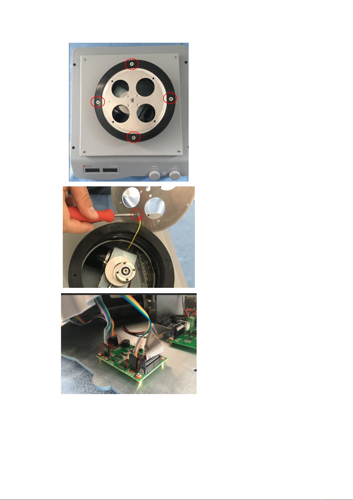
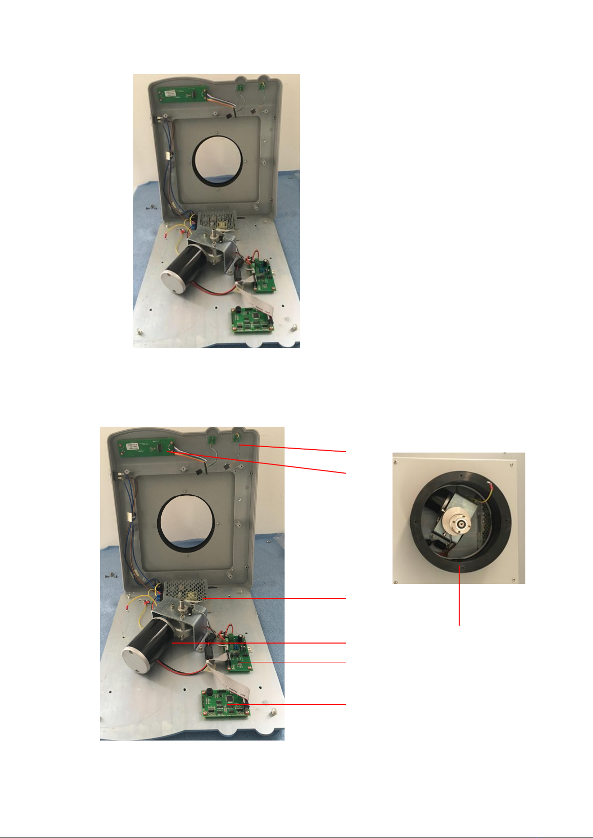
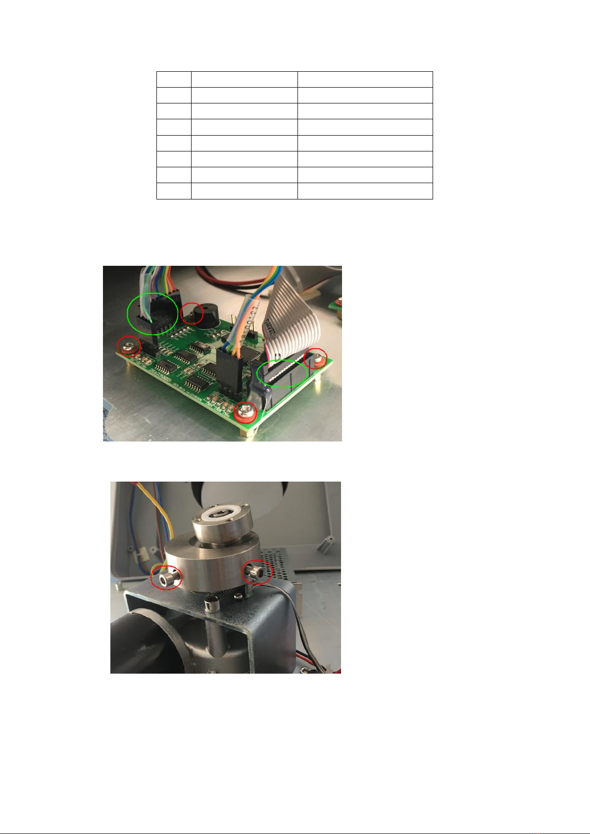
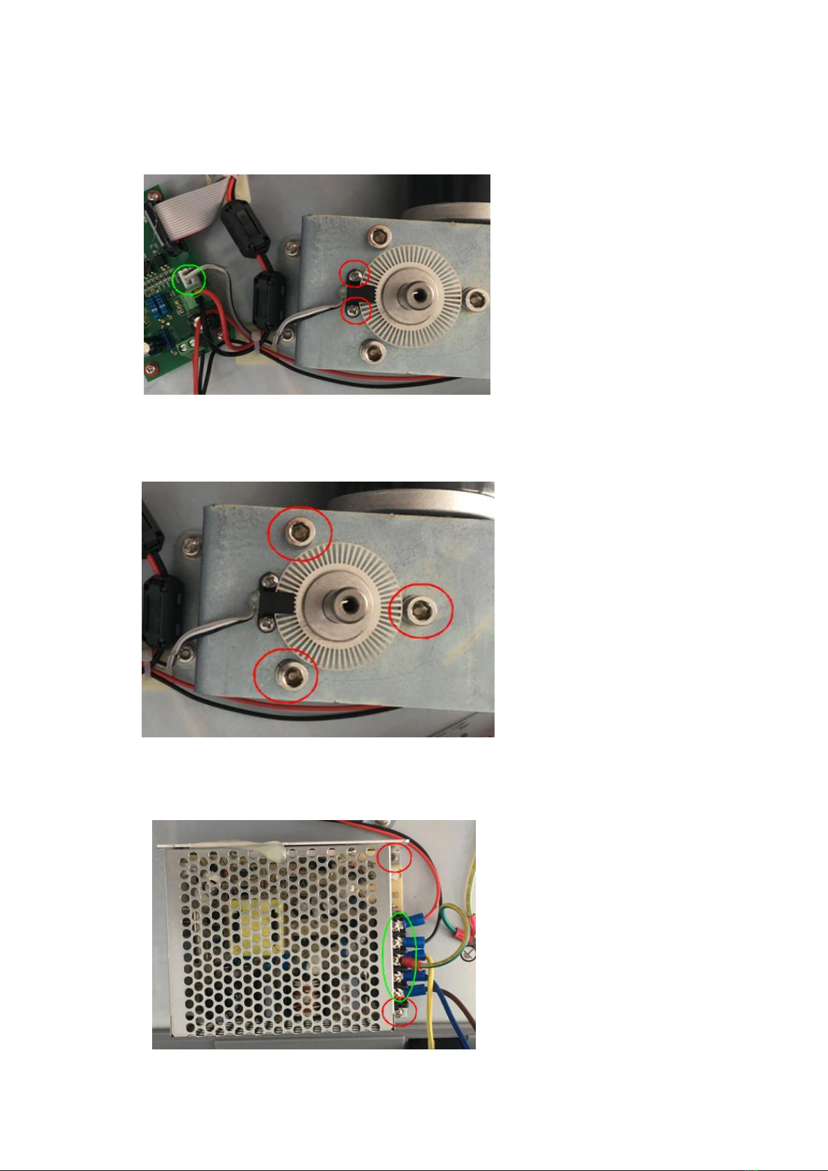
2.6 Replacement of motor drive board
As shown in the left figure, unplug
connectors marked by green circle,
loosen the 2 screws marked by blue
circle and unplug 2 cables, remove 4
screws marked by red circle, then
replace motor drive board, then
assemble it in sequence.
Chapter 3: Trouble shooting
FAULT
CODE
PROBLEM CAUSE SOLUTION
E01
Instruments can’t be power
on
The power line is
unplugged
Check whether the power line is
unplugged, an power on it again
The power switch put off Put on the power switch
The fuse is broken Replace the fuse
Power board is failure Replace power board
Main board is failure Replace mainbaord
The display screen is
broken
Replace display screen
E02 Instrument doesn’t
movement
No setting target speed Set a target speed, the speed
indicator is on.
The drive board is failure
Replace the drive board, please
reference chapter 2.5
power board is failure Replace power board
component
Motor is failure Replace motor
E03 LCD display garbled
characters
Display board is failure Replace display board
E04
Instrument speed is not
accurate
Photo electronic switch is
failure
Replace photo electronic switch
The position of photo
electronic switch goes
failure
Adjust the position of photo
electronic switch