DLS ECAM220.XX MAGNIFICA START User manual

Doc. Nr.: DSDL_22007_C
[1]
Data Sheet and Service Manual
ECAM220.XX MAGNIFICA START
Date: 17.05.2022
Uploaded: 03.05.2023

Doc. Nr.: DSDL_22007_C
[2]
1 Summary
2TECHNICAL DATA................................................................................................................................3
3HYDRAULIC DIAGRAM........................................................................................................................4
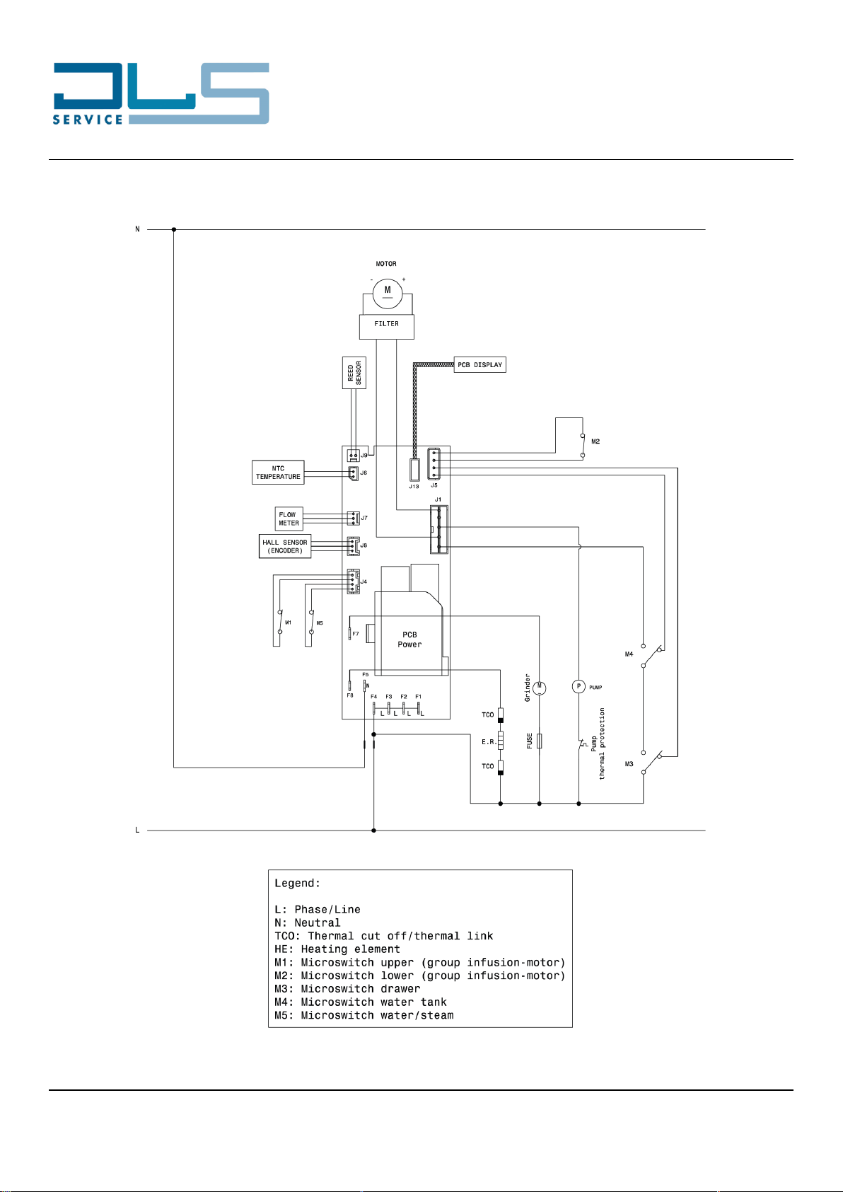
4WIRING DIAGRAM ...............................................................................................................................5
4.1 Practical Outline.............................................................................................................................5
4.2 Theorical Outline............................................................................................................................6
5WORKING PRINCIPLE.........................................................................................................................7
5.1 MICROSWITCHES, SENSORS AND SOLENOID VALVES...........................................................7
6TEST MODE .........................................................................................................................................8
6.1 LOAD TEST MODE........................................................................................................................8
6.2 DISPLAY TEST MODE ..................................................................................................................9
6.3 RESET ENCODER ......................................................................................................................10
7STATISTICS MODE............................................................................................................................11
8A. HEATING ELEMENTS RESISTANCE CHECK...............................................................................13
9COFFEE TEMPERATURE TEST........................................................................................................14

Doc. Nr.: DSDL_22007_C
[3]
2 TECHNICAL DATA
Voltage –Frequency –Input Power 220 - 240 V –50 / 60 Hz –1450 W
Stand-by Button OFF ≈ 0.23 Wh
COMPONENTS
Pump 230 V AC –48 W –15 bar
Grinder motor AC
Transmission motor DC with position encoder
Coffee thermoblock
- Temperature probe NTC sensor
- Thermal fuse TCO 192 °C
- Heating element 230 V AC –1400 W

Doc. Nr.: DSDL_22007_C
[4]
3 HYDRAULIC DIAGRAM

Doc. Nr.: DSDL_22007_C
[5]
4 WIRING DIAGRAM
4.1 Practical Outline

Doc. Nr.: DSDL_22007_C
[6]
4.2 Theorical Outline

Doc. Nr.: DSDL_22007_C
[7]
5 WORKING PRINCIPLE
5.1 MICROSWITCHES, SENSORS AND SOLENOID VALVES
MICROSWITCHES
Function
Logic
M1 = UPPER MICROSWITCH
Detects when the infuser is on top
position
“NC”, it opens when the infuser is in top
position
M2 = LOWER MICROSWITCH
Detects when the infuser is on down
position
“NO”, it closes when the infuser is in
down position
M3 = DRAWER MICROSWITCH
Detects when the drip tray is in
correct position
3-pin micro switch. When the drip tray is
inserted:
- the contact for the drip tray
detection is OPEN;
- the contact for the transmission
motor power supply is CLOSED.
M4 = WATER TANK
MICROSWITCH
Detects the presence of the water
tank
3-pin micro switch. When the water tank is
inserted:
- the contact for the water tank
detection is OPEN;
- the contact for the transmission
motor power supply is CLOSED.
M5 = HOT WATER / STEAM
MICROSWITCH
Detects when the hot water / steam
knob is in “I” position
“NC”, it opens when the user move the
knob to the “I” position
REED AND ENCODER
Function
Logic
REED SENSOR EMPTY WATER
TANK
Detects when the water level is at
minimum
HALL SENSOR ENCODER
Detects rotations of transmission
motor

Doc. Nr.: DSDL_22007_C
[8]
6 TEST MODE
To activate the test mode proceed as follows:
1. The appliance must be plugged-in and in stand-by mode.
2. Remove the drip tray.
3. When the request to insert the drip tray prompts on the
display, press and hold + + (see the
position, not the graphic of the buttons) until the drip tray
alarm goes off.
4. Insert the drip tray.
5. Select the desired test mode.
6.1 LOAD TEST MODE
After having accessed the test mode as indicated previously, press
to access the LOAD TEST MODE.
Press one of the icons as shown in the image n°3 to activate the
relative load.
LED legend:
steady ON: available functions (the steam LED lights up
when the knob is in the position “I”)
slow blinking: active load
fast blinking: UP/DOWN micro switch pressed

Doc. Nr.: DSDL_22007_C
[9]
6.2 DISPLAY TEST MODE
After having accessed the test mode as indicated, press to
access the DISPLAY TEST MODE:
During the display test mode all the LEDs are light up.
When a button is pressed, only the LED of that button remains ON,
while all the other buttons will be turned OFF.
In particular, by pressing each of the 3 buttons below, in addition to
the button LED, also the two neighbour warning LEDs will
illuminate steadily:
NOTICE: The DISPLAY TEST MODE will reset the following
settings in the appliance:
first run: the machine will ask again for hydraulic circuit
filling
language: the machine will ask again to choose the
language
filter installation: if the filter installation function was
enabled, it will be disabled

Doc. Nr.: DSDL_22007_C
[10]
6.3 RESET ENCODER
After having accessed the test mode as indicated, press to
start the RESET ENCODER:
LED legend:
blinking: reset in progress
steady ON: reset done

Doc. Nr.: DSDL_22007_C
[11]
7 STATISTICS MODE
The appliance allows the reading of the statistics data to
understand exactly how the machine operated along the time.
To access the STATISTICS MODE:
make sure the appliance is ready to use (i.e. in ready-for-
coffee mode)
hold + pressed for at least 5 seconds
The and LEDs blink to confirm the STATISTICS MODE.
Button
Statistics
Number of descales
Litres of water used
Number of filters installed
Number of coffee beverages
Number of steam erogations
Press the desired button to display the corresponding statistics data:
After having pressed the desired button, the appliance will display the corresponding statistic value with
the sequential flashing of the below lights:

Doc. Nr.: DSDL_22007_C
[12]
Example: To display a total amount of 104 coffee beverages, the appliance will display:
1. the , and LEDS flash to advice which icons will be involved on the count
2. the LED flashes once
3. the machine emits a long beep to advice that the second value is 0
4. the LED flashes 4 times
To exit the statistics mode, press the SETTINGS button again or wait for 120 seconds without operating
on the machine.
The appliance will come back to the ready to use mode.

Doc. Nr.: DSDL_22007_C
[13]
8 A. HEATING ELEMENTS RESISTANCE CHECK
Thermoblock resistance value: ≈ 35 Ohms.
Resistance/temperature characteristics for the thermoblock NTC:

Doc. Nr.: DSDL_22007_C
[14]
9 COFFEE TEMPERATURE TEST
Complaints from end users about coffee temperature are quite frequent. They are mainly due to incorrect
appliance adjustments or to an incorrect expectation by the customer.
A coffee temperature measurement is required all the times any of these complaints are encountered.
To perform the coffee temperature test, follow in sequence the below steps:
1. Turn the appliance ON
2. Run 1-2 rinse cycles to warm up the hydraulic circuit
3. Select to prepare a X2 ESPRESSO COFFEE (refer to the user manual for more details)
4. Start the coffee preparation
5. Wait until at least 20ml of coffee have been delivered into the cup
6. Measure the coffee flow temperature at about 2÷10mm from the coffee spout, as shown in the
below picture:
The optimal indicative temperature measurement for coffee should be:
82°C ± 3°C for the minimum level of temperature
84°C ± 3°C for the medium level of temperature
86°C ± 3°C for the maximum level of temperature
Refer to the user manual for more details to how set the level of temperature.
Table of contents
Other DLS Coffee Maker manuals
Popular Coffee Maker manuals by other brands

Black & Decker
Black & Decker DLX851 use and care manual

Caffitaly System
Caffitaly System S23 instruction manual

Jura Capresso
Jura Capresso IMPRESSA 68192 Operating instructions and warranty

Gaggia
Gaggia EVOLUTION operating instructions

Nespresso
Nespresso magimix M 200 user manual

Dash
Dash DCBCM550 instructions