Doc. Nr.: DSDL_20013_A
[6]
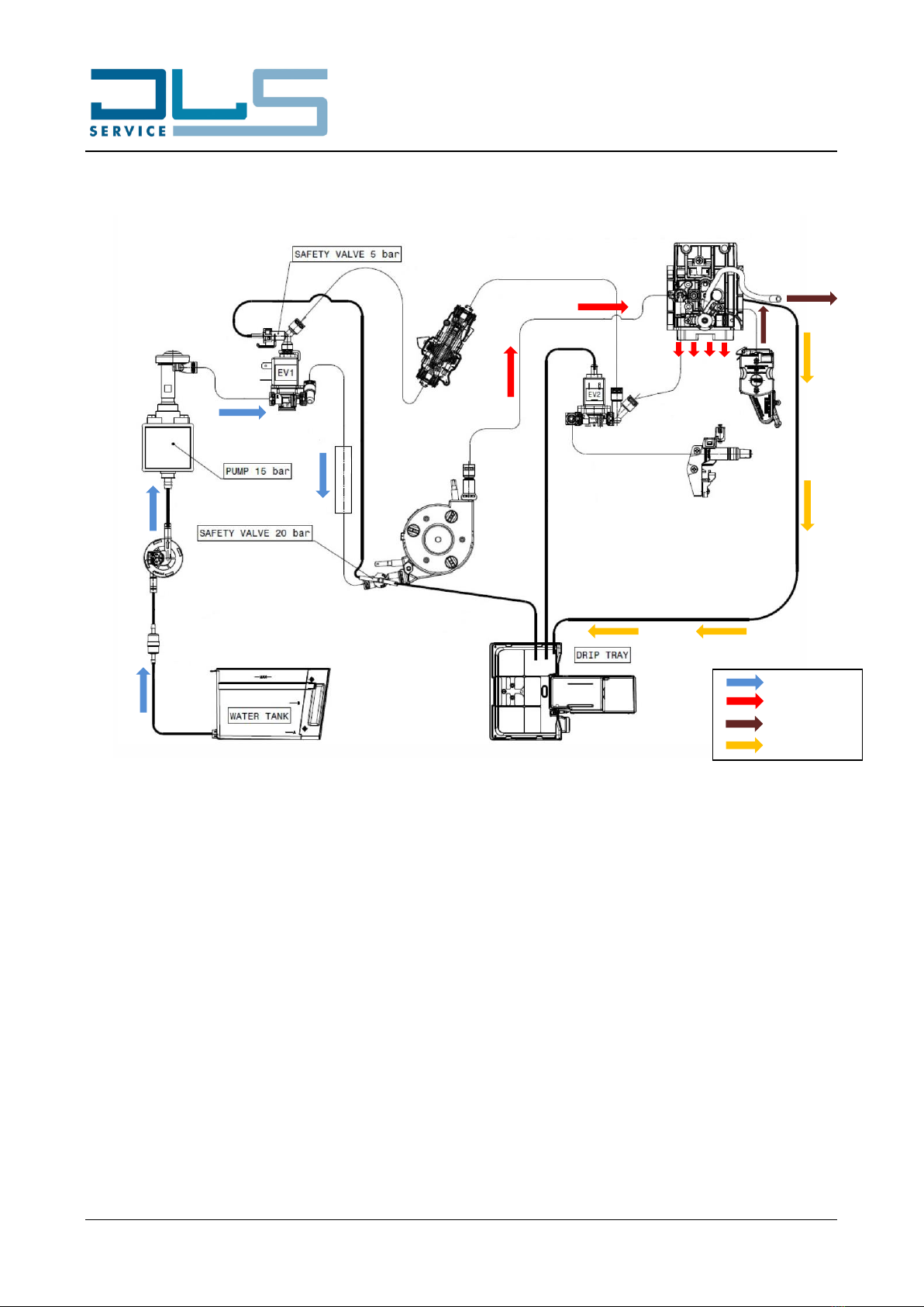
5. WORKING PRINCIPLE
5.1. MICRO SWITCHES, SENSORS AND SOLENOID VALVES
Detects when the infuser is on top
position
“NC”, it opens when the infuser is in top
position
Detects when the infuser is on down
position
“NO”, it closes when the infuser is in down
position
Detects when the drip tray is in
correct position
3-pin micro switch. When the drip tray is
inserted:
- the contact for the drip tray
detection is OPEN;
- the contact for the transmission
motor power supply is CLOSED.
M4 = WATER TANK MICRO
SWITCH
Detects the presence of the water
tank
3-pin micro switch. When the water tank is
inserted:
- the contact for the water tank
detection is OPEN;
- the contact for the transmission
motor power supply is CLOSED.
Detects the presence of the milk jug
“NC”, it opens when the accessory is
present
M6 = HOT WATER SPOUT /
CLEAN MICRO SWITCH
Detects the presence of the hot
water spout or starts the CLEAN
function for the milk jug
“NC”, it opens when the hot water spout is
present or when the milk jug knob is in the
CLEAN position
Detects rotations of transmission
motor
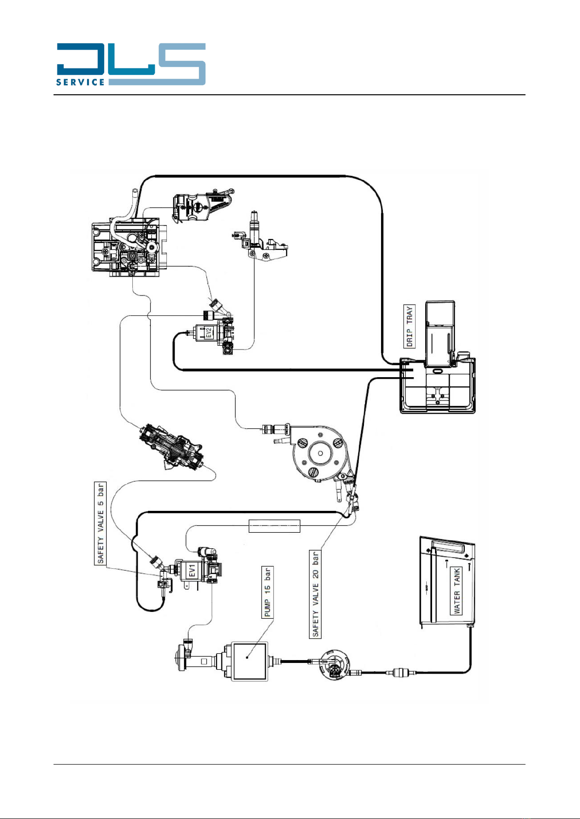
EV1 = 3-ways solenoid valve
Allows the water flow to go to the
Thermoblock
When activated, the water flow goes to the
Thermoblock.
When deactivated, the water flow goes to
the Steamer.
EV2 = 3-ways solenoid valve
Allows the hot water and the steam
to flow to the connection nozzle
When activated, the water/steam flow
goes to the connection nozzle