DMF RW-1016 Quick start guide

DIVERSIFIED METAL FABRICATORS, INC.
DMF 665 Pylant Street Atlanta, Georgia 30306
Parts (404) 607-1684Parts Fax (404) 879-7888parts@dmfatlanta.com
Service Department (404) 879-7882service@dmfatlanta.com
Phone (404) 875-1512 Fax (404) 875-4835info@dmfatlanta.com
http://www.dmfatlanta.com
Parts & Service Manual
RW-1016
February 2019
SERIAL NUMBER (FRONT) ________________________
SERIAL NUMBER (REAR) ________________________
NOTE:
Please refer to the serial numbers when ordering parts or
inquiring about warranty items.

DIVERSIFIED METAL FABRICATORS, INC. RW-1016
© 2017 DMF, Inc. All Rights Reserved.
Message from DMF
No matter what your job function is, Operation, Installation, Maintenance, or Repair, it is your
responsibility to familiarize yourself with the entire manual. Once you have read the entire
manual, there are some specific sections that you will want to pay special attention to,
depending on your role.
If you find anything missing, incorrect or unclear in this manual, please contact us. We are
always trying to improve our manuals.
Manuals, service bulletins and general information are available on our website listed below.
We reserve the right to update our manuals without notice. You can download a current manual
at our website (http://www.dmfatlanta.com).
Thank you for choosing DMF Railgear. We make every effort to provide quality, safe and rugged
products for the railroad. We hope you'll find our gear to be satisfactory in every way. We take
product support very seriously, so if you have any questions, please contact us.
Contact:
Diversified Metal Fabricators
665 Pylant St. NE
Atlanta, GA 30306
(404) 875-1512
(404) 875-4835 Fax
(404) 607-1684 Parts
http://www.dmfatlanta.com
info@dmfatlanta.com
Ship to:
668 Drewry St. NE
Atlanta, GA 30306

DIVERSIFIED METAL FABRICATORS, INC. RW-1016
© 2017 DMF, Inc. All Rights Reserved.
TABLE OF CONTENTS
SECTION 1.0 GENERAL INFORMATION
1.1 General Description, Weights & Capacities ...............1-2
1.2 Currently Supported Chassis .................................1-4
1.3 Railgear Components and Terminology ...................1-3
SECTION 2.0 OPERATIONS
2.1 Before You Operate the Railgear.............................2-2
2.2 Highway Operation ...............................................2-4
2.3 Getting on the Rail................................................2-4
2.4 Getting off the Rail................................................2-5
2.5 Emergency Hand Pump .........................................2-6
SECTION 3.0 ROUTINE MAINTENANCE
3.1 Inspection and Maintenance...................................3-2
3.2 Fluids and Lubrication ...........................................3-3
3.3 Rail Wheel Wear Gauge .........................................3-5
3.4 Troubleshooting....................................................3-7
3.5 Derailment...........................................................3-8
SECTION 4.0 RAILGEAR INSTALLATION
4.1 Before You Begin..................................................4-3
4.2 Wheel Modification Kit Installation ..........................4-7
4.3 Mounting Kit Installation........................................4-9
4.4 Railgear Installation..............................................4-10
4.5 Alignment............................................................4-12
4.6 Rail Wheel Loads ..................................................4-14
4.7 Exhaust Modification .............................................4-17
4.8 Rail Test, Weld-out, & Final Adjustment...................4-X
4.9 Install Provided Accessories ..................................4-X
4.10 Installation Review .............................................4-X
SECTION 5.0 HYDRAULIC & ELECTRICAL SYSTEMS
5.1 Hydraulic System..................................................5-2
5.2 Electrical System..................................................5-8
5.3 Hydraulic & Electrical Schematics............................5-9
5.3 Hydraulic & Electrical Component Drawings..............5-11
SECTION 6.0 RAILGEAR PARTS
6.1 Before Ordering Parts............................................6-2
6.2 Railgear Mounting Kits...........................................6-3
6.3 Railgear Core Assemblies.......................................6-13
6.4 Suspension Assemblies, Bearings, & Wheels.............6-17
6.4 Optional Components............................................6-25
6.4 Chassis/Wheel Modification Kits..............................6-9

DIVERSIFIED METAL FABRICATORS, INC. RW-1016
© 2017 DMF, Inc. All Rights Reserved.
This page intentionally left blank.

DIVERSIFIED METAL FABRICATORS, INC. RW-1016
`
© 2017 DMF, Inc. All Rights Reserved. 1-1
SECTION 1.0 GENERAL INFORMATION
1.1 GENERAL DESCRIPTION, WEIGHTS & CAPACITIES......................................... 1-2
1.1.1 Features and Description .................................................................................1-2
1.1.2 Weights and Capacities....................................................................................1-3
1.2 CURRENTLY SUPPORTED CHASSIS ................................................................. 1-4
1.2.1 GM................................................................................................................1-4
1.2.2 Ford ..............................................................................................................1-4
1.2.3 Ram ..............................................................................................................1-4
1.3 RAILGEAR COMPONENTS AND TERMINOLOGY................................................ 1-5
1.3.1 Key Railgear Components ................................................................................1-5

DIVERSIFIED METAL FABRICATORS, INC. RW-1016
1-2 © 2017 DMF, Inc. All Rights Reserved.
1.1 GENERAL DESCRIPTION, WEIGHTS & CAPACITIES
1.1.1 Features and Description
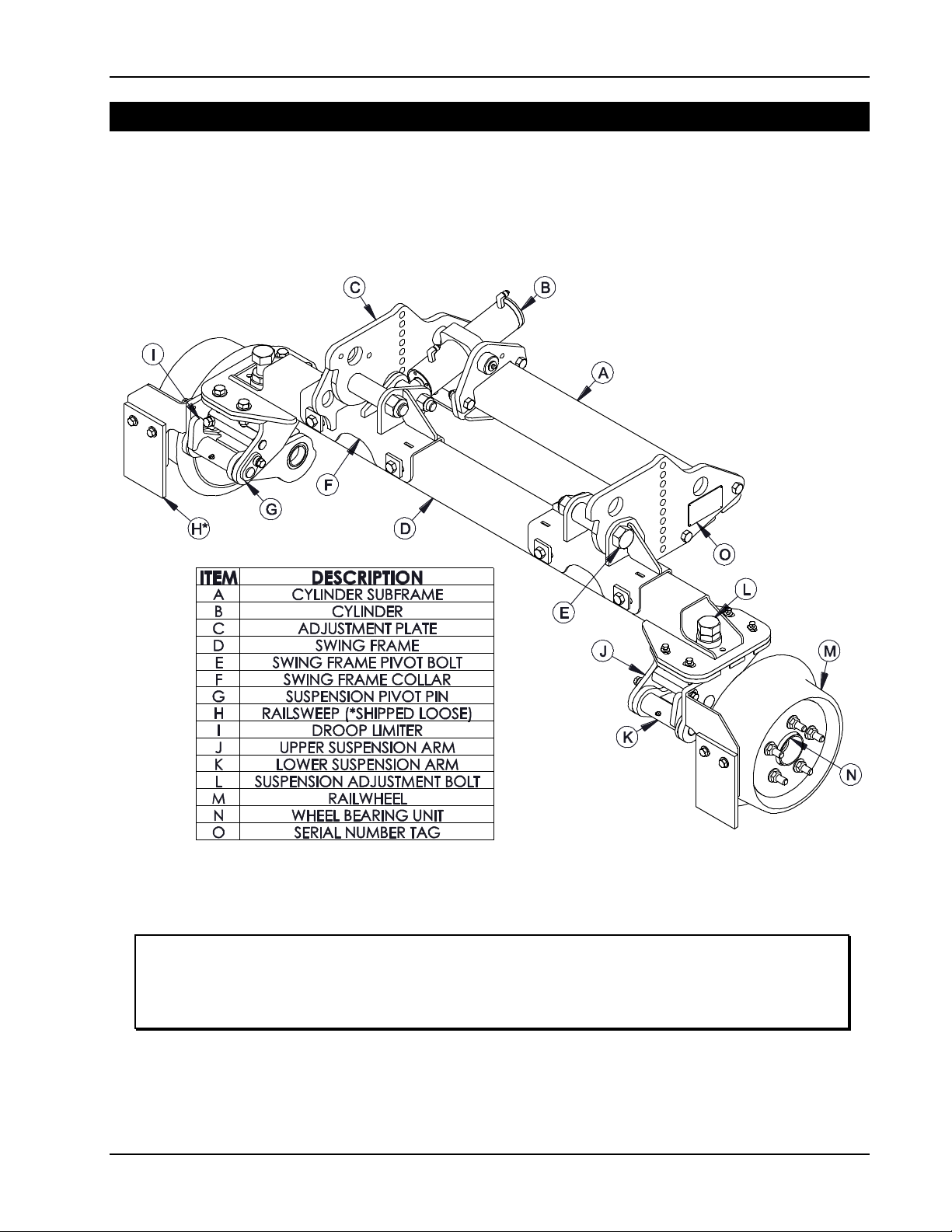
DMF’s RW-1016 Railgear is designed for Class 2 & 3 single rear wheel heavy duty pickup trucks.
The front and rear Railgear assemblies are visually similar and share many common
components. Railgear assemblies attach to the truck frame with bracketry specific to the
vehicle make and model. All structural members and brackets are constructed of carbon steel.
Select components are hot dip galvanized or zinc plated for additional corrosion resistance.
Each Railgear assembly is actuated is by a single hydraulic cylinder. In the rail position, the
Railgear is “over-center”, which prevents a hydraulic failure from allowing the gear to collapse.
In the highway position, hydraulic locking valves prevent the Railgear from falling due to a
system leak. An emergency hand pump allows the gear to be lifted into the highway position in
the event of hydraulic system failure while on rail.
RW-1016 Railgear features an independent suspension system at each railwheel. Rubber
springs provide a smooth and quiet ride over uneven rail surfaces. The load on each railwheel
can be adjusted individually. The 10” guide wheels are machined from cast steel, and mounted
to automotive-style unitized hub bearings that maximize service life and minimize maintenance
Unlike most of our larger models, RW-1016 does not lift the steer axle off the rail. All vehicle
tires remain in contact with the rail. RW-1016 does not provide braking or drive power, and
relies on the vehicle tires for those functions.
Most vehicles require installation of alternate wheels and tires to properly align the vehicle’s
track width to the rails. DMF offers Wheel Modification Kits for many popular chassis models for
use on standard gage rail. These kits include the necessary rims, wheel adapters, TPMS
sensors, steering stops, and steering wheel locks.
RW-1016 was engineered to meet a wide range of customer requirements in its standard
configuration. DMF also offers many options for RW-1016 to meet your specialized needs.
Contact DMF for additional information on standard and optional features.
RW-1016 Standard Features
56.5” rail gauge
Steel tread railwheels
Wireless Railgear controls
4-corner rail wheel insulation
Hydraulic locking valves, highway & rail position (front & rear)
Low-profile 12VDC hydraulic power unit and emergency hand pump
Front and rear rail sweeps and de-rail skids
RW-1016 Optional Features
Truck wheel and tire modification kits
In-cab switchable rail shunting
Heavy duty cable pinoff system (front & rear)
Rubber tread railwheels
Additional wireless handheld transmitter for backup/emergency use
Hardwired Railgear controls @ bumpers and/or in cab
Railgear position sensing for GPS/Telematics integration
Custom rail gauges & wheel profiles

DIVERSIFIED METAL FABRICATORS, INC. RW-1016
`
© 2017 DMF, Inc. All Rights Reserved. 1-3
1.1.2 Weights and Capacities
Typical Chassis Application: Class 2-3 heavy duty pickup trucks with single rear wheels.
Capacity: 500-1,000 lb. per railwheel @ 40 MPH.
Typical Railgear Weights:
Exact weights vary based on many factors, including options and chassis make/model. Table
1.1 below summarizes weights typical of installations using RW-1016 Railgear.
Item
Typical Weight (lbs.)
Front Railgear (Steel Railwheels)
285
Front Mounting Kit
20
Rear Railgear (Steel Railwheels)
290
Rear Mounting Kit
60
19.5" Steel Wheels, Adapters, and Typical Tires (4X/Each)
680
Hydraulic Pump and Hand Pump
40
Wiring, Hoses, Misc. Accessories
35
Removal of stock 17” steel wheels/tires, including spare
(415)
Removal of spare tire hoist and heat shielding
(10)
Typical Net Weight of Railgear Installation
982

DIVERSIFIED METAL FABRICATORS, INC. RW-1016
1-4 © 2017 DMF, Inc. All Rights Reserved.
1.2 CURRENTLY SUPPORTED CHASSIS
Chassis selection for Railgear applications is critical to ensure the finished upfit complies with
manufacturer and federal guidelines. Many combinations of trim levels, engines, drivetrains,
and cab/box sizes present installation challenges or entirely prevent the use of Railgear.
General Upfitting Notes:
The Railgear installer is the party responsible for certifying that the completed vehicle
complies with all federal safety regulations, gross axle weight ratings (GAWR), and gross
vehicle weight rating (GVWR).
Truck option content and upfitter installed equipment may cause some configurations
approved below to be overweight.
The completed vehicle must not exceed any GAWR or GVWR with 150 lbs. in every seat
per 49 CFR 567.4.
Unless indicated otherwise, all models below include:
Only single rear wheel variants. Dual rear wheel models are not typically supported.
Only pickup or box delete variants. Chassis cab models are not typically supported.
The list below includes basic guidelines regarding chassis suitability, but is not exhaustive. See
DMF Technical Reference Bulletin TRB009 for additional details.
Please contact DMF for assistance or questions with chassis and option selection for
your project.
1.2.1 GM
2011 –Present 2500 & 3500
oSnow Plow Prep (VYU; 4x4 only) or Railgear Prep (8W9, gas only) required
oNo CNG engine
1.2.2 Ford
2017 –Present F-250 & F-350
oSnow Plow Prep Required ( option 473; 4x4 only)
2008 –2016 F-250 & F-350
oSnow Plow Prep Required (option 473; 4x4 only)
1.2.3 Ram
2014 –Present 2500 and 3500
oCoil spring rear suspension required (no air)
oNo CNG engine

DIVERSIFIED METAL FABRICATORS, INC. RW-1016
`
© 2017 DMF, Inc. All Rights Reserved. 1-5
1.3 RAILGEAR COMPONENTS AND TERMINOLOGY
1.3.1 Key Railgear Components
Figure 1.3.1 identifies key components of RW-1016 Railgear assemblies. Appearances of some
components may vary depending on chassis make/model/year, as well as selected Railgear
options. These item descriptions will be used throughout this manual.
Figure 1.3.1 RW-1016 Key Railgear Components
(Front Shown –Rear Similar)
FOR DETAILED INSTALLATION INSTRUCTIONS, SEE
SECTION 4.0
FOR DETAILED PARTS DIAGRAMS, SEE SECTION 6.0

DIVERSIFIED METAL FABRICATORS, INC. RW-1016
1-6 © 2017 DMF, Inc. All Rights Reserved.
This page intentionally left blank.

DIVERSIFIED METAL FABRICATORS, INC. RW-1016
© 2017 DMF, Inc. All Rights Reserved. 2-1
SECTION 2.0 OPERATIONS
2.1 BEFORE YOU OPERATE THE RAILGEAR ........................................................... 2-2
2.1.1 Vehicle Turning Radius, Clearances, and Approach Angles....................................2-2
2.1.2 Highway Speeds .............................................................................................2-2
2.1.3 Pinoff Systems and Locations ...........................................................................2-2
2.1.4 Railgear Controls ............................................................................................2-3
2.1.5 Daily Inspection..............................................................................................2-3
2.2 HIGHWAY OPERATION ................................................................................... 2-4
2.3 GETTING ON THE RAIL ................................................................................... 2-4
2.3.1 Getting Onto the Tracks...................................................................................2-4
2.3.2 Lower Rear Guide Wheels ................................................................................2-4
2.3.3 Lower Front Guide Wheels................................................................................2-4
2.3.4 On the Tracks.................................................................................................2-4
2.4 GETTING OFF THE RAIL .................................................................................. 2-5
2.4.1 Removing Truck from Track .............................................................................2-5
2.5 EMERGENCY HAND PUMP OPERATION............................................................ 2-6

DIVERSIFIED METAL FABRICATORS, INC. RW-1016
2-2 © 2017 DMF, Inc. All Rights Reserved
2.1 BEFORE YOU OPERATE THE RAILGEAR
2.1.1 Vehicle Turning Radius, Clearances, and Approach Angles
Class 2-3 vehicles with Railgear installed typically require inset wheels and tires to properly
align with the rails. Steering stops are normally installed to prevent the inset wheels and tires
from contacting critical suspension, brake, and frame components. Compared to a stock
vehicle, the installation of steering stops usually significantly increases the turning radius. Do
not operate a vehicle equipped with steering stops on public roads until you are comfortable
with the modified handling characteristics. If you hear any noises while making hard turns,
immediately have the vehicle inspected for possible interference issues.
Installation of Railgear typically reduces front and rear ground clearance, as well as approach
angles. In many installations, the guide wheels extend slightly beyond the corners of the front
bumper. To avoid equipment and property damage, operators should be familiar with the
modified clearances and working envelope before driving the vehicle.
2.1.2 Highway Speeds
Vehicles with Wheel Modification Kits should not exceed the wheel or tire ratings. The operator
is responsible for maintaining lug nut torque. Lug nut torque must be checked according to
Section 3.1.3. Operators should have access to a torque wrench.
2.1.3 Pinoff Systems and Locations
NOTE:
ALL RW-1016 Railgear assemblies feature cylinders that are
equipped with external locking valves to prevent the Railgear
from falling the in the event of a hydraulic system failure.
Optional pinoff systems provide an added degree to protection
against unintended Railgear movement.
When equipped, pinoff systems should always be used to secure
the Railgear in the rail or highway position.
Walk around vehicle and identify the location of any pinoff systems installed on the Railgear.
Familiarize yourself with how to engage/disengage the pinoff systems.

DIVERSIFIED METAL FABRICATORS, INC. RW-1016
© 2017 DMF, Inc. All Rights Reserved. 2-3
2.1.4 Railgear Controls
RW-1016 Railgear is typically controlled using a wireless handheld remote. The remote should
be stored in a safe, easily accessible location inside the cab. A master power switch inside the
cab must be turned on to supply power to the hydraulic pump and wireless receiver.
It may take several seconds for the handheld remote to “pair” with the base unit when the
system is turned on by the master power switch. There is no power switch on the remote; it will
power off after several minutes of activity to extend battery life. Pushing any button on the
remote will “wake” the handheld remote.
Figure 2.1.1 Wireless Handheld Remote
2.1.5 Daily Inspection
Before operating your Railgear-equipped vehicle, whether for highway or rail use, it is
imperative that you perform a daily inspection –see Section 3.1.1 for Daily Inspection List. If
any items found during your inspection do not conform to requirements, it is your responsibility
to take corrective action before any use of the vehicle.

DIVERSIFIED METAL FABRICATORS, INC. RW-1016
2-4 © 2017 DMF, Inc. All Rights Reserved
2.2 HIGHWAY OPERATION
Before operating a Railgear-equipped vehicle on the highway:
1. Verify Railgear is in highway position.
2. Verify that any pinoff systems (front and rear) are properly engaged (if equipped).
3. Steering wheel lock has been removed (if applicable).
4. Verify that any in-cab switches for Railgear system power remain off when operating on-
road.
2.3 GETTING ON THE RAIL
2.3.1 Getting Onto the Tracks
1. At the track crossing, drive past the track, then back the vehicle onto the rails. Align the
rear Railgear to the rail first; this makes it easier to engage the front Railgear.
2. Turn on the Railgear system power switch. Leave the truck running and in park, with the
parking brake set.
2.3.2 Lower Rear Guide Wheels
1. Disengage the rear Railgear pinoff system (if equipped). If a pinoff is difficult to disengage,
momentarily press the “up” button on the Railgear controls to remove load from the pin.
2. Use the wireless remote to lower the rear guide wheels. The flanges of the guide wheels
should be to the inboard sides of the railheads. It may be necessary to adjust truck position
slightly.
3. When both wheels are fully down and properly engaging rail, engage the pinoff (if
equipped).
2.3.3 Lower Front Guide Wheels
1. If necessary, drive the truck into position to line up the front guide-wheels with the rail.
2. Ensure that the front Railgear pinoff is disengaged (if equipped).
3. Ensure that the vehicle tires are pointed straight ahead.
4. Use the wireless remote to lower the front guide wheels.
5. Once Railgear is fully engaged on rail, re-engage the front pinoff (if equipped).
6. Turn off the Railgear system power when not in use to prevent unintended movement.
7. Install the Velcro steering wheel lock between the top of the steering wheel and the steering
column.
8. Disengage the truck’s parking brake when you are ready to proceed.
2.3.4 On the Tracks
Recommendations given here are for welded rail in good condition. Jointed rail or rail in poor
condition, require further reductions in speed and additional caution.
Do not exceed posted track speed limit, and at no time exceed 40 MPH while on the track.
Operator is responsible for determining safe speed.
All four guide wheels on RW-1016 Railgear are typically insulated and will not operate
crossing gate circuits. Optional switchable shunt systems can be installed to selectively
control when the vehicle will be detected on rail.
Reduce speed while in reverse and/or at all crossings, curves, branch lines, switches and
frogs (no more than a slow walking pace is recommended).
Traction is reduced on the track, especially in wet conditions.
Braking distance is increased on the track, especially in wet conditions.
Do not slide tires or guide wheels on the tracks as this will cause premature wear.
Do not exceed the maximum rated capacity of the equipment.

DIVERSIFIED METAL FABRICATORS, INC. RW-1016
© 2017 DMF, Inc. All Rights Reserved. 2-5
2.4 GETTING OFF THE RAIL
2.4.1 Removing Truck from Track
1. Safely pull onto the track crossing, paying attention to traffic and other obstacles.
2. Turn on the Railgear system power switch. Leave the truck running and the transmission in
park with the parking brake set.
3. Disengage both the front and rear Railgear pinoffs (if equipped).
4. Lift both sets of Railgear (there is no preference for removal order).
5. Re-engage ALL pinoffs for safe travel in the highway position.
6. Turn off the railgear system power when not in use to prevent unintended movement.
7. Stow the Velcro steering wheel lock.
8. Make sure surrounding area is free and clear of any obstacles and vehicles before pulling off
of the rail and onto the road.

DIVERSIFIED METAL FABRICATORS, INC. RW-1016
2-6 © 2017 DMF, Inc. All Rights Reserved
2.5 EMERGENCY HAND PUMP OPERATION
THE EMERGENCY HAND PUMP CAN ONLY BE USED TO
RAISE THE RAILGEAR. IT IS NOT DESIGNED OR
INTENDED TO DEPLOY THE RAILGEAR.
The emergency pump is provided to allow a malfunctioning vehicle to be removed from the rail
in the event of an electrical fault or pump failure. The emergency pump rocker switch, typically
installed near the hand pump, is held up to enable hydraulic flow to the rear Railgear & down
for the front Railgear.
To stow the Railgear using the emergency hand pump:
1. Locate hand pump handle in the cab or another safe storage area.
2. Ensure that Railgear is clear from obstructions.
3. Disengage both front and rear Railgear pinoffs (if equipped).
4. Turn the vehicle key to the ignition position.
5. Insert hand pump handle.
6. Hold Emergency Pump Switch UP to select the REAR railgear.
7. Pump rear Railgear to stowed position and engage pinoff (if equipped).
8. Hold Emergency Hand Pump Switch DOWN to select the FRONT railgear.
9. Pump front Railgear to stowed position and engage pinoff (if equipped).
Safety Notes
Be aware of pinch points when manually raising Railgear.
Do not drive vehicle at normal highway speeds if Railgear is not adequately restrained.
If Railgear is chained up and not fully in highway position, be aware of your ground
clearance!
FOR HYDRAULIC SYSTEM DIAGRAMS, PLEASE SEE
SECTION 5.3.

DIVERSIFIED METAL FABRICATORS, INC. RW-1016
© 2017 DMF, Inc. All Rights Reserved. 3-1
SECTION 3.0 ROUTINE MAINTENANCE
3.1 INSPECTION AND MAINTENANCE................................................................... 3-2
3.1.1 Daily Maintenance...........................................................................................3-2
3.1.2 Weekly Maintenance........................................................................................3-2
3.1.3 Bi-Annual Maintenance or as required................................................................3-2
3.1.4 Annual Maintenance or as required ...................................................................3-2
3.2 FLUIDS AND LUBRICATION ............................................................................ 3-3
3.2.1 Grease Fitting Locations...................................................................................3-4
3.3 RAIL WHEEL WEAR GAUGE ............................................................................. 3-5
3.4 TROUBLESHOOTING ....................................................................................... 3-7
3.5 DERAILMENT .................................................................................................. 3-8

DIVERSIFIED METAL FABRICATORS, INC. RW-1016
3-2 © 2017 DMF, Inc. All Rights Reserved.
3.1 INSPECTION AND MAINTENANCE
To assure safe and reliable operation, Diversified Metal Fabricators recommends the following
inspection and maintenance guidelines detailed below. Government or corporate regulations
may require additional inspections not covered below. Please ensure that you are aware of any
additional recurring inspections that pertain to your Railgear, and have them completed
according to required regulations.
Vehicles operated in the following severe-duty conditions may need more frequent inspection
and maintenance than suggested below:
Extreme hot or cold temperatures
Operation on steep grades
Extended exposure to road salt
High mileage use
3.1.1 Daily Maintenance
Verify Railgear is fully stowed and has not leaked down.
Visually inspect for hydraulic fluid leaks and bent, broken, or damaged components.
Check hydraulic fluid level.
Verify there are no loose or missing fasteners, including the lug nuts on rail wheels and
vehicle wheels.
Inspect the general condition of the rail wheels.
With rail wheels in the highway position, spin each one to check for irregular noise,
resistance or roughness in the bearing unit.
Check and correct tire pressures. Inspect tires for abnormal wear, including inboard
sidewalls
3.1.2 Weekly Maintenance
In addition to the daily maintenance outlined above:
Lubricate front & rear pin-off assemblies (if equipped) with a light lubricant.
Inspect railwheel flange wear. Uneven or excessive wear may indicate alignment or rail
wheel load problem.
Inspect rubber railwheel treads (if equipped).
Inspect suspension components including rubber springs for excessive wear or cracking.
Verify that ABS sensor wires and brake lines are restrained and not contacting the rims.
Grease all grease fittings on front (7) and rear (7) Railgear assemblies.
oWhen possible, apply grease with the Railgear in the highway position to
maximize grease uptake.
NOTE:
See diagram M101601 on following page for grease fitting locations and
recommended lubricants.
3.1.3 Bi-Annual Maintenance or as required
In addition to the weekly maintenance outlined above:
Check torque on all lug nuts (rail wheels, wheel adapters, and vehicle wheels).
Check torque on wheel bearing adapter bolts (4X per railwheel, see Section 6.4).
3.1.4 Annual Maintenance or as required
In addition to the weekly maintenance outlined above:
Verify the operation of the emergency hand pump. If pump does not operate, check that the
pump is properly primed (see Section 5.1).
Check Railgear alignment (see Section 4.5).
Check Railgear wheel loads (see Section 4.6).
Replace handheld wireless remote batteries (QTY 3 AAA)

DIVERSIFIED METAL FABRICATORS, INC. RW-1016
© 2017 DMF, Inc. All Rights Reserved. 3-3
3.2 FLUIDS AND LUBRICATION
Hydraulic Oil: Dexron III ATF (DMF supplied electric/hydraulic power units)
Grease Fittings:
oFactory Standard: Citgo Syndurance Premium Synthetic 460 #2
oWarm Climates: Mystik JT-6 Hi-Temp Multi-Purpose Grease #2
Wheel bearing hub units: Rail wheel bearing units are completely sealed. No lubrication
or adjustment is necessary. They are not are not user serviceable and must be replaced
as a unit. See Section 6 for replacement parts diagrams.

21(($&+6,'(
21(($&+6,'(
5(&20(1'('*5($6(
'0)67$1'$5'
&,7*26<1'85$1&(35(0,806<17+(7,&
:$50&/,0$7(6
0<67,.-7+,7(0308/7,385326(
127(6
)52175$,/*($56+2:15($56,0,/$53$576+,''(1)25&/$5,7<
:+(13266,%/(*5($6(,1+,*+:$<326,7,21720$;,0,=(837$.(
5(9
'$7(
'(6&5,37,21
%<
$33
/2&$7,21
47<
'(6&5,37,21
&</,1'(552'(1'
6,'(6+2:1
6:,1*)5$0(3,927
&</,1'(575811,21287(5
&<,1'(575811,21,11(5
6,'(6+2:1
6863(16,213,9273,1
%5($.6+$53('*(6;0$;
72/(5$1&(681/(6663(&,),('
0
5(9
'5$:,1*180%(5
7,7/(
'$7(
$33'%<
'5$:1%<
7+,6'5$:,1*&217$,16&21),'(17,$/35235,(7$5<,1)250$7,212)',9(56,),('
0(7$/)$%5,&$7256,1&'0)&23<5,*+7'0)$//5,*+765(6(59('
7$0
5:
0$18$/*5($6(32,1765:
)5$&0$&+
)5$&27+(5
;
;;
;;;
'5,//6,=(6
$1*8/$5
685)),1,6+
7+5($'6
0,&52
$$1'%
'0)
Table of contents