Stinson TC12-4884 User manual

1 OCT 30, 2020
STINSON OWL-LITE
ARROW BOARD
MODEL NO. TC12-4884
USER MANUAL

2 OCT 30, 2020
GENERAL DESCRIPTION................................................................................................................................. 3
INSTALLATION............................................................................................................................................... 4
CAB CONTROLLER ......................................................................................................................................... 7
ARROW BOARD CONTROLLER....................................................................................................................... 8
TROUBLESHOOTING...................................................................................................................................... 8
SPECIFICATIONS .......................................................................................................................................... 10
SPARE PARTS............................................................................................................................................... 11
Figure 1 INSTALLATION ELECTRICAL ............................................................................................................. 4
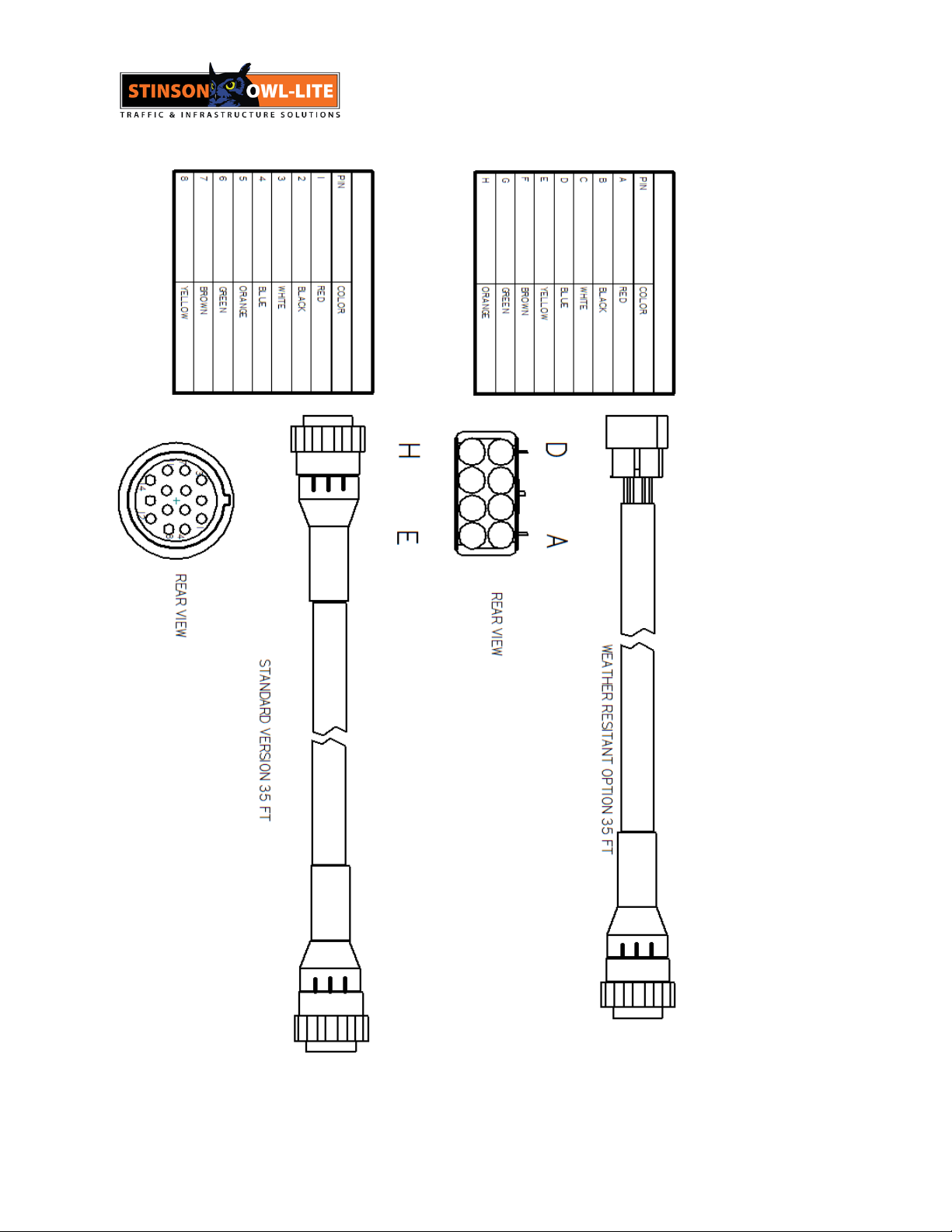
Figure 2 INSTALLATION CABLES .................................................................................................................... 6
Figure 3 TERMINAL BLOCK WIRING .............................................................................................................. 7
Figure 4 CAB CONTROLLER ........................................................................................................................... 8
Figure 5 FUSE LEGEND .................................................................................................................................. 9
Figure 6 OUTLINE DWG............................................................................................................................... 11
Figure 7 BOM .............................................................................................................................................. 14
Figure 8 INTERCONNECT DWG................................................................................................................... 15
Table 1 TROUBLE SHOOTING GUIDE............................................................................................................. 9

3 OCT 30, 2020
GENERAL DESCRIPTION
Stinson Arrow Board model no. TC12-4884 conforms to MTO specification for TC12 Arrow Boards
The standard configuration is a vertical mount.
Switches on the cab controller will activate the bar lights, left arrow lights, right arrow lights, and
wing actuators. A beacon switch is also provided as an option.
To activate the Arrow Board, turn the Bar Switch to the UP position. The Bar LEDs will now be
ON and flashing. Left and right Arrows can now be deployed.
To de activate the Arrow Board, turn the bar switch to the OFF position. The wings will return to
the extended position and all LEDs on the Arrow Board will turn off.
See section CAB CONTROLLERfor more detail.
The TC12-4884 is typically mounted in a vertical position A Cab Controller and connecting cable
are typically supplied. Standard cable lengths are 35 ft. For custom cable lengths please contact
Stinson Customer Service
Custom racks are available that allow the Arrow Board to mount horizontally. To deploy the
Arrow board in the vertical position, a switch on the Cab Controller operates an actuator, lifting
the Arrow Board to the vertical position.
For wireless communication between the Cab Controller and the Arrow Board, a wireless option
is available.
A Solar option is available. With this option, the Arrow Board is energized by a solar panel. A
separate battery charger system allows the Arrow Board to operate independently from the
truck battery.
For more information on these and other options Contact Stinson Customer Service 1-800-561-
6639 for more information.
Stinson has the capability of custom design engineering if your installation requirements are
unique or special.

4 OCT 30, 2020
INSTALLATION
The electrical installation is shown in figure 1. The fuse shall be physically located at the Battery
terminal and rated at 15 AMP. A 10 AWG cable is required to power the Arrow Board.
Figure 1 INSTALLATION ELECTRICAL

5 OCT 30, 2020

6 OCT 30, 2020
Figure 2INSTALLATION CABLES

7 OCT 30, 2020
Figure 3 TERMINAL BLOCK WIRING
CAB CONTROLLER
The top row of toggle switches control Arrow Board LEDs and actuators. To activate the LEDs
the BAR switch is moved to the ON or to the UP position. The bar row is now activated. The
LEDs will flash approximately 40-50 times per second.
The left and right LEDs and actuators can now be deployed by turning the left and right toggle
switches to the UP or ON position.
To de activate the Arrow Board, turn the bar switch to the OFF position. The wings will return to
the extended position and all LEDs on the Arrow Board will turn off.
There is an option for an auxiliary or beacon switch. See Stinson Customer Service.
905-669-2360
ON
TC12 4884

8 OCT 30, 2020
Figure 4 CAB CONTROLLER
ARROW BOARD CONTROLLER
The Arrow Board Controller is located inside the Arrow Board.
A photo sensor is located on the printed circuit board. A clear window located on the rear panel of the
Arrow Board allows light to illuminate the photocell. During nighttime operation, the LED intensity is
reduced.
For proper operation of the photocell, this window should be clear and clean.
The removal and installation of the Arrow Board Controller is straight forward.
TROUBLESHOOTING
In the event of failure, please review Table 1 below.
The controller is fused to protect against short circuits in the Arrow Board.
There are LED indicators that will illuminate under the following Conditions
1. A short circuit in the Left Arrow, Right Arrow or Bar will open F4, F5, F6.
2. A wing Actuator failure or short circuit will open F1. Under these conditions LED 5 will
illuminate indicating fuse F1 has failed or is open.
3. F3 is not employed.
In the case of fuse failure, attempt to find short location prior to applying power.
Replace fuses with sizes indicated in the Fuse Table below.
SYMPTON
CAUSE
The Cab Controller does not operate LEDs.
There is no LED indication on the Cab
Controller.
The Arrow Board is not connected to the
Battery or the Battery polarity is reversed.
The Cab Controller does not operate LEDs .
Battery voltage is under 11.5 volts.
Check for open fuses (F4, F5, F6 5 Amps).
See fuse legend figure 5.

9 OCT 30, 2020
Wing Actuators do not function.
Check voltage at Wing Actuator. If the
voltage is present, the Wing Actuator has
failed.
If there is no Actuator voltage, check for open
Actuator fuse (F1 15 AMP). See fuse legend
figure 5.
The Arrow Board LED intensity is low
Probably the solar window at the rear of the
Arrow Board is dirty not allowing the photo
sensor to operate at full intensity.
Table 1 TROUBLE SHOOTING GUIDE
Figure 5FUSE LEGEND

10 OCT 30, 2020
FUSE TABLE
FUSE DESIG
FUNCTION
LED IND
FUSE TYPE
F3
NOT ACTIVE
N/A
N/A
F1
LEFT/RIGHT ACTUATORS
LED 5
15 AMPS
F6
ARROW RIGHT LEDS
LED 1
5 AMPS
F4
BAR LEDS
LED 2
5 AMPS
F5
ARROW LEFT LEDS
LED 3
5 AMPS
SPECIFICATIONS
See Stinson Customer Service for specification details 1-800-561-6639
ELECTRICAL
Maximum Peak Current Draw with Bar and One Arrow Flashing 3.0 Amps
Average Current Draw with Bar and One Arrow Flashing 1.5 Amps
MECHANICAL
Weight 160 Lbs (73.5 kg)
Dimensions See Figure 6

11 OCT 30, 2020
Figure 6 OUTLINE DWG
SPARE PARTS
All major components can be replaced. See Stinson Customer Service for spare part service 1-
800-561-6639. Please see BOM on fig 7 for complete parts description.

12 OCT 30, 2020

13 OCT 30, 2020

14 OCT 30, 2020
Figure 7 BOM

15 OCT 30, 2020
Figure 8INTERCONNECT DWG

16 OCT 30, 2020
WARRENTY
WARRANTY POLICY
Thank you for purchasing this quality STINSON EQUIPMENT LIMITED (STINSON) product. We are proud to stand
behind every new STINSON product and this warranty policy is our commitment to you. Please read it carefully.
STINSON warrants that this product will conform to the manufacturer’s standard specifications without defects in
materials and workmanship as outlined below:
Product/ Component
Warranty Period
Mechanical Assembly; (trailers, metal sign
frames, mounting hardware, arrow boards)
-1 year
-Standard coatings excepted
Molded Products; (barrels, cones, markers)
-1 year on plastic integrity
Electrical and Electronic
-1 year
Signs and Sheeted Products
-Sheeting defects, 30 days
Components, sub-assemblies and devices produced by other manufacturers are covered separately and individually
under warranties provided by the specified manufacturer.
There are no warranties expressed or implied which extend these warranty periods. The loss of the product, loss of
time, inconvenience, commercial loss or consequential damages, including cost of any labour, is not covered.
STINSON reserves the right to change the design of the product without assuming any obligation to modify any
product manufactured. This warranty is granted to the original purchaser of the product and is not assignable to any
subsequent purchaser or user. Any leasing or borrowing of these goods or other use beyond normal demonstration of
the same shall be deemed to be use by the original purchaser. The period of this warranty shall commence on the
date of delivery to the first original purchasers. Proof purchase and delivery date may be required when warranty
service is requested.
The sole remedy under this warranty shall be the repair or replacement of parts which have been determined to be
defective after inspection by an approved representative of STINSON. STINSON reserves the right to request the
return of parts replaced under this warranty or in disputable fitness and must be consulted for authorization before
any such return. All defective parts replaced under this warranty shall become property of STINSON. If as claimed
defect cannot be identified or reproduced in service, the purchaser will be held responsible for the costs of
replacement or remanufactured parts. STINSON shall not be responsible for the transportation or mileage costs
associated with repair or replacement of warranted products or parts. The costs of labour associated with corrections
under this warranty shall be reimbursed at a rate deemed reasonable by STINSON if such labour is not performed by
STINSON factory approved personnel. Tampering with the serial number or posted safety and operating instructions
may constitute a breech of this warranty. This warranty shall not extend to any goods or parts which have been
altered, repaired, operated, or maintained outside of approved STINSON procedures or directives. This warranty
does not cover damage resulting from causes beyond the control of STINSON, including without limitation; misuse,
abuse, neglect, or accident; external electrical faults, power surges, or power failure; damage occurring in shipment
or from improper transportation, installation, operation or application; or damage resulting from improper usage or use
of the product with components, accessories or other items not supplied by STINSON. The end-user is responsible
for the selection, use and results obtained from the product.
This warranty applies only to products that have been paid for according to terms under which the product has been
invoiced. Further, the buyer agrees that STINSON will not be required to honour any warranty claim from a customer
whose account at STINSON is not current according to STINSON’s payment terms. This warranty is exclusive and in
lieu of all other warranty, expressed or implied including warranties of merchantability or of fitness for purpose, and
no other warranties which extend beyond the descriptions on the face hereof. The remedies set forth herein and
manufacturer shall not be liable for special, indirect or consequential damages. The obligations of STINSON
hereunder shall not exceed the cost of the equipment or part upon which such liability is based.
Stinson Equipment Ltd. 130 Creditstone Rd. Concord Ontario L4K 1P2

17 OCT 30, 2020
130 Creditstone Road
Concord Ontario Canada L4K 1P2
Ph ( 905 ) 669-2360 Fax ( 905 ) 669-3537
Company
Address
Phone
Fax
Product
Serial #
Date Purchased
130 Creditstone Road
Concord Ontario Canada L4K 1P2
Ph ( 905 ) 669-2360 Fax ( 905 ) 669-3537
Company
Address
Phone
Fax
Product
Serial #
Date Purchased
Environmental

18 OCT 30, 2020
-40 C –50 C Operational
-40
Table of contents
Other Stinson Automobile Accessories manuals
Popular Automobile Accessories manuals by other brands

Maxxhaul
Maxxhaul 80401 Instruction manual & parts list

Thule
Thule 973-1 Fitting instructions

Prorack
Prorack K541 Fitting instructions

Double Apex
Double Apex Escort Mute Button installation instructions

Trailboss
Trailboss QTFD962L Fitting instructions

ULTIMATE SPEED
ULTIMATE SPEED 340578 1910 Assembly and Safety Advice

aFe Power
aFe Power 51-82722 instruction manual

Bracketron
Bracketron LUX LX1-851-2 manual

Soundoff Signal
Soundoff Signal MPower PMP2BK004 manual

Safe Fleet
Safe Fleet Bustin Slide & Go Platform Use and maintenance guide

Innova
Innova 3040c owner's manual

Metra Electronics
Metra Electronics 70-1787 installation instructions