DMG amigo User manual

DMG SpA
Via Quarto Negroni, 10
00040 CECCHINA (ROMA) • ITALIA
Tel. +39 06930251 • Fax +39 0693025240
NOTE:
Leave this document close to the emergency
telephone after installation
Installation manual
Vers. 1.2 - English
AMIGO
- ETS8128CM
- ETS8128MR + ETS8128CS
Emergency Telephone
(EN 81-28 compliant)
AMIGO
93010044_E_amigo_060324-0_EN.cdr

231
2
Machine room device
Lift car slave device
Phone receiver
Feeder / battery charger
(optional)
Top/bottom of car slave device
SYSTEM COMPONENTS
Code Description
AMIGO
Emergency telephone
Car master device
ETS8128CM
ETS8128MR
ETS8128CS
ETS8128SL
CITCOC
ETS8128CH
NOTES:
AMIGO
Emergency telephone
ETSGSM GSM Module

30 3
CAUSA
Impossible to hear the operator voice
from the interphone (CITCOC)
Wrong connections Check connections
Volume is set at minimum Use the trimmer on ETS8128MR
device to raise the volume
4. Troubleshooting
AMIGO
Emergency telephone
PROBLEM POSSIBLE CAUSE SOLUTION
AMIGO
Emergency telephone
INDEX
1. page 4
1.1 ...............................................
1.2 ..................................................
1.3 ................................................
1.4
1.5
..............................
1.6
1.8 Externalcalls...................................................page 9
2.1 ....................................
2.2 ............................
2.3 ............................
2.4 ............................................
3. Programming
3.1 ...................................................
3.2 .....................................................
3.3 Menumap .....................................................
3.4 Standby.......................................................
3.5 .............................................
3.6 ..............................................
3.7 ..............................................
3.8 Incomingcalls ..................................................
3.9 ..................................................
3.10 ...............................................
3.11 .................................................page 24
3.12 ................................................page 26
3.13 ....................................page 27
3.14 Calldelay......................................................page 28
4.
Product description
Technical features
Main functions
ignals
Alarm cycle description for
"SINGLE DEVICE" configuration
"3-DEVICE" configuration (EN 81-28 norm)
"4-DEVICE" configuration (EN 81-28 norm)
Function keys
Troubleshooting
page 4
page 4
Available s page 4
Basic alarm cycle setting for calls towards standard phone numbers
(Without DTMFcommunication protocol) . . . . . . . . . . . . . . . . . . . . . . . . . . . . . . page 5
calls towards standard phone numbers
(Without DTMFcommunication protocol) page 6
Basic alarm cycle setting for calls towards service center . . . . . . . . . . . . . . . . . page 7
1.7 calls towards service center . . . . . . . . . . . . . . . . . . page 8
1.9 OperationwithGSMnetwork.......................................page 9
2. Installation guide page 10
page 10
page 10
page 11
Installation instructions page 12
2.5 Basicconnections ...............................................page 13
2.6 Advanced connections (EN 81-28 norm) . . . . . . . . . . . . . . . . . . . . . . . . . . . . . . page 15
page 16
page 16
Navigation page 16
page 17
page 18
Numbers from 1 to 6 page 18
Service call number page 19
Number of attempts page 20
page 21
Dialing options page 22
Conversation time page 23
Voice messages
Site identification
Type of communication protocol
page 30

429
AMIGO AMIGO
Emergency telephone
1. -
• C ee §
• ee §
1.1 -
• +/- 15%
• 38mA+/- 15%
•
•O
• Dimensions : 90x150x20 mm Weight : 160 gr.
1.2 -
• Store capacity up to 6
•1
• Recordable
•
•
•D
• Two-way communication
•
• Management of i
•
• Inter
• Local or remote alarm reset management
• Alarm filters management in case of working system or open doors with cage at floor
• Local or remote management of “wait for call status”
1.3 - Available s
•"Alarm sent" - "Alarm registered" signal management
Product description
AMIGO is a programmable phone dialler for lifts complying with EN 81-28 norm requirements.
It is available in the following versions:
ar Master device (code ETS8128CM) - s 2.1 and 2.2
Machine room Master device (code ETS8128MR + ETS8128CS) - s 2.3
Technical features
Power supply: 12Vdc
Absorption in stand-by:
Absorption during the call cycle: 150mA
ptional: Feeder/battery charger (code ETS8128CH)
Main functions
phone numbers for emergency calls
phone number dedicated to service calls
"Site identification” message
Possibility of storing two customized messages associated to "Low battery charge" and
"Regular operation" inputs
Programmation unit with LCD screen and keyboard (16 keys)
ialler status visible on LCD display
time programmable by the user
“Low battery charge” outbound call
ncoming system check calls
Manual dialing feature to check phone line availability
phone system between lift car and machine room (only with "Machine room" version)
ignals
Emergency telephone

28 5
1.4 - Basic alarm cycle setting for calls towards standard phone numbers
(Without DTMFcommunication protocol)
1) Enter in programming mode (see § 3.4)
2) Record the phone numbers to be called in case of emergency (see § 3.5)
3) Record the “Service Call” phone number where LOW BATTERY CHARGE and REGULAR
OPERATION service calls must be forwarded (see § 3.6)
4) Select the desired number of alarm cycles (see § 3.7)
5) Select the type of “Incoming calls” (see § 3.8)
6) Select tones or pulses mode (see § 3.8)
7) Select conversation time (see § 3.10)
8) Make sure that the message forward option is enabled (see § 3.11)
9) Record the SITE IDENTIFICATION message (see § 3.11)
10) Record the REGULAR OPERATION message (see § 3.11)
11) If the installation is provided with optional battery charger ETS8128CH (see § 2.6.2) record the
LOW BATTERY CHARGE message (see § 3.11)
12) Make sure that the “No protocol” option is enabled (see § 3.13)
13) Select the type of “Call delay” (see § 3.14)
Notes:
- If you do not want to enable the SITE IDENTIFICATION message, deselect the message
forward option (see § 3.11) and disregard § 8-9
- The first phone number must be always recorded, otherwise the alarm cycle will not be triggered
3.14 - Call delay
When set on “No delay”, the autodialler starts the alarm cycle immediately upon activation of the
alarm pushbutton positioned on one of the alarm devices.
When set on “5 sec delay”, the autodialler starts the alarm cycle only after 5 seconds of continuous
activation of the alarm pushbutton positioned on one of the alarm devices (to avoid accidental calls).
To set “Call delay”, press WRITE to access programming mode, then press “1” to set “5 sec delay”
or “0” to set “No delay”. Press OK to store the setting (If OK is not pressed within 30 seconds, the
setting is cancelled and the system goes back to Stand by).
1st number
Call delay
(5 sec delay/no delay)
NEXT WRITE
Stand by
DMG
Amigo XX vX.X
Call delay
ESC
OK
To store
ESC
Stand by
DMG
Amigo XX vX.X
NEXT
1st number
No delay
5 sec delay
0
1
If no key is entered within 30 seconds, the autodialler will automatically get back to stand-by.
AMIGO
Emergency telephone
AMIGO
Emergency telephone

627
1.5 - calls towards standard phone numbers
(Without DTMFcommunication protocol)
1) T
2)
3)
4) After having taken the emergency call and listened to
5)
6)
7)
- when a new alarm cycle is triggered;
- by pressing the “*” key on the autodialler during the “Wait for call” status or during Stand-by;
- by pressing the “8” from a remote phone receiver (see § 1.8).
8) The autodialler exits from “Wait for call” status and gets back to Stand-by:
- after 3 minutes if “Incoming calls” is set on “OFF”;
- by pressing the “*” key on the autodialler;
- by pressing the “8” from a remote phone receiver (see § 1.8).
Notes:
- The alarm cycle is executed regardless from the availability of phone line. This is because different
line signals in some countries may prevent the alarm message to be sent.
- I
ETS8128CS.
Alarm cycle description for
The alarm cycle is common to all versions of the AMIGO telephone
In case of emergency, if a passenger in the lift car (or other person trapped in the lift installation)
pushes the alarm button of one of the alarm devices, the Emergency Telephone triggers the alarm
cycle and follows this sequence:
he Emergency Telephone connects to the phone line and dials the first stored number.
The "alarm sent" yellow LED switches on and after 6 seconds the "site identification " message is
played three times (if recorded and if the Messages option is activated; see § 3.11).
If the Emergency Telephone does not receive any answer for 60 seconds, it calls the second
stored number. In case of no answer, the next programmed number is called and so on. If all
programmed numbers are called without reply for the programmed number of times (see § 3.7),
the line is disconnected, the "alarm sent" LED stays on and the Emergency Telephone returns to
the stand-by mode, ready to start a new alarm cycle.
the "Site identification" message, the
external operator (Call Center or other rescue service) can establish the two-way conversation by
pressing the “0” key. If the operator hangs down the line or does not press the “0” key, the
Telephone dials the next number.
When conversation time expires (this parameter can be set by the customer, see § 3.10) the
Emergency Telephone sends 5 tones to the operator. If the operator presses the "*" key,
conversation time is extended; if the operator presses the "#" key the telephone disconnects the
telephone line, the yellow "alarm sent " LED switches off and the green "alarm received” LED
switches on. The message "Wait for call" will appear on the display.
When the Emergency Telephone is in "Wait for call" status (duration can be set by the client, see
§3.8), the external operator can connect to the site by dialing its phone number. When the
communication is established, the Telephone sends 5 tones; the same tones are passed to signal
that conversation time is about to end (conversation time can be extended by pressing the "*"
key). When the conversation is over, the Emergency Telephone returns to “Wait for call”.
The "alarm received" LED can be switched off:
- by pressing the "alarm off" button wired to the ALARM OFF input of the terminal board of the
autodialler (if the "alarm off" input is bridged the signal switches off automatically at the end of the
alarm cycle);
n the Quadriphony configuration (see §2.3), "alarm sent" and "alarm received" lights are placed in
the Car Slave Device
3.13 - Type of communication protocol
AMIGO Emergency Telephone can also dialogue with external service centers (Protocols currently
implemented: ANEP, ADEMCO, SCANTRONICS). In such cases, site identification and/or status of
installation data are automatically exchanged between the autodialler and the service center,
therefore there is no need to voice record the service messages (Site identification, Low battery and
Regular operation).
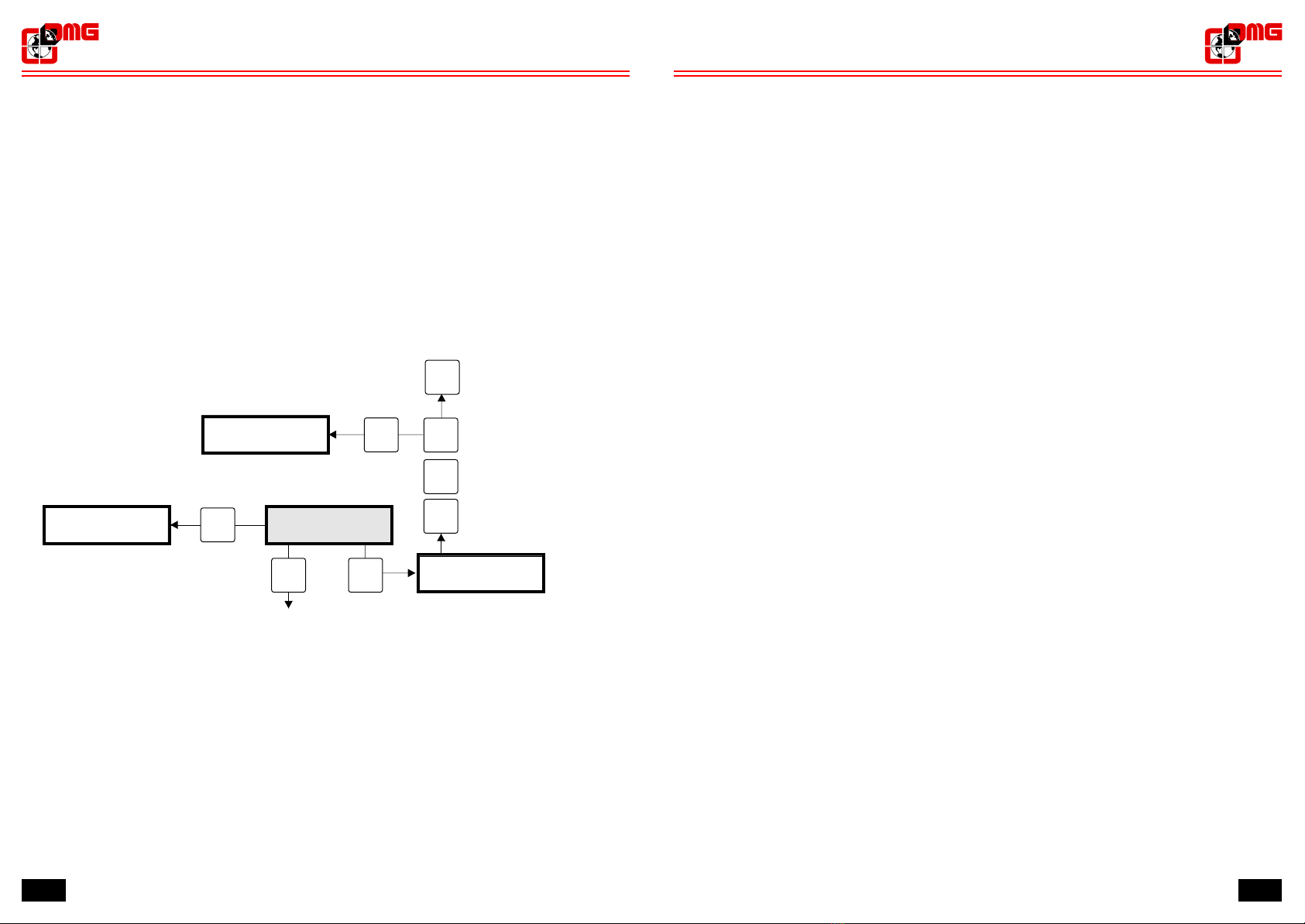
To set the “Protocol type” press WRITE to enter the programming mode and press:
- “0” to set “No protocol”
- “1” to set ”ANEP” protocol
- “2” to set “ADEMCO” protocol
- “3” to set “SCANTRONICS” protocol
then press OK to store the setting (If OK is not pressed within 30 seconds, the setting is cancelled and
the system goes back to Stand by).
Call delay
Protocol type
(Anep/Ademco/
Scantronics/No protocol)
NEXT WRITE
Stand by
DMG
Amigo XX vX.X
Anep
Ademco
Protocol type
ESC
0
1
OK
To store
ESC
Stand by
DMG
Amigo XX vX.X
NEXT
Call delay
Scantronics
No protocol
2
3
If no key is entered within 30 seconds, the autodialler will automatically get back to stand-by.
AMIGO
Emergency telephone
AMIGO
Emergency telephone

26 7
1.6 - Basic alarm cycle setting for calls towards service center
1) Enter in programming mode (see § 3.4)
2) Set the “1st number” with the phone number of the service center to be called in case of
emergency (see § 3.5)
3) Set the “Service Calll no.” with the phone number of the service center to be called in case of
emergency (see § 3.6)
4) Select the desired number of alarm cycles (see § 3.7)
5) Select the type of “Incoming calls” (see § 3.8)
6) Select tone mode (see § 3.9)
7) Select conversation time (see § 3.10)
8) Set the ID number provided by the selected service center (see § 3.12)
9) Select the type of protocol to be used to communicate with the service center (see § 3.13)
10) Select the type of “Call delay” (see § 3.14)
3.12 - Site identification
When “Protocol Type” is set on either “ANEP” or “Ademco” or “Scantronics” (see § 3.13), the
autodialler does not send voice service messages but dialogues with service centers exclusively
through DTMF tones.
In such case, an ID Number must be entered into the autodialler. The ID number will be sent to the
service center and will allow the unique identification of the installation which generated the
emergency call.
To set the “ID Number”, press WRITE to access programming mode, then enter the site identification
number (max 8 digits). Press OK to store the setting (If OK is not pressed within 30 seconds, the
setting is cancelled and the system goes back to Stand by).
Id number
Protocol type
Id number
(MAX 8 digit number)
ESC
NEXT WRITE
To store the number
OK
ESC
NEXT
Protocol type
Stand by
DMG
Amigo XX vX.X
Stand by
DMG
Amigo XX vX.X
If no key is entered within 30 seconds, the autodialler will automatically get back to stand-by.
AMIGO
Emergency telephone
AMIGO
Emergency telephone

825
1.7 - calls towards service center
1) T
2)
3)
4) After having taken the emergency call and received
5)
6)
7)
- when a new alarm cycle is triggered;
- by pressing the “*” key on the autodialler during the “Wait for call” status or during Stand-by;
- by pressing the “8” from a remote phone receiver (see § 1.8).
8) The autodialler exits from “Wait for call” status and gets back to Stand-by:
- after 3 minutes if “Incoming calls” is set on “OFF”;
- by pressing the “*” key on the autodialler;
- by pressing the “8” from a remote phone receiver (see § 1.8).
Notes:
- The alarm cycle is executed regardless from the availability of phone line. This is because different
line signals in some countries may prevent the alarm message to be sent.
- I
ETS8128CS.
Alarm cycle description for
The alarm cycle is common to all versions of the AMIGO telephone
In case of emergency, if a passenger in the lift car (or other person trapped in the lift installation)
pushes the alarm button of one of the alarm devices, the Emergency Telephone triggers the alarm
cycle and follows this sequence:
he Emergency Telephone connects to the phone line and dials the first stored number.
The "alarm sent" yellow LED switches on.
If the Emergency Telephone does not receive any answer for 60 seconds, it recalls the same
stored number. In case of no answer for the programmed number of times (see § 3.7), the line is
disconnected, the "alarm sent" LED stays on and the Emergency Telephone returns to the stand-
by mode, ready to start a new alarm cycle.
the "ID number", the external operator of the
service center can establish the two-way conversation.
When conversation time expires (this parameter can be set by the customer, see § 3.10) the
Emergency Telephone sends 5 tones to the operator. If the operator presses the "*" key,
conversation time is extended; if the operator presses the "#" key the telephone disconnects the
telephone line, the yellow "alarm sent " LED switches off and the green "alarm received” LED
switches on. The message "Wait for call" will appear on the display.
When the Emergency Telephone is in "Wait for call" status (duration can be set by the client, see
§3.8), the external operator can connect to the site by dialing its phone number. When the
communication is established, the Telephone sends 5 tones; the same tones are passed to signal
that conversation time is about to end (conversation time can be extended by pressing the "*"
key). When the conversation is over, the Emergency Telephone returns to “Wait for call”.
The "alarm received" LED can be switched off:
- by pressing the "alarm off" button wired to the ALARM OFF input of the terminal board of the
autodialler (if the "alarm off" input is bridged the signal switches off automatically at the end of the
alarm cycle);
n the Quadriphony configuration (see §2.3), "alarm sent" and "alarm received" lights are placed in
the Car Slave Device
To record the “Site Identification” message, press “1”. A confirmation message (“Are you sure?”) will
pop up: press “1” to start recording (”0” to stop recording), speaking close to the microphone for 20
seconds max.
To record the “Low battery charge” message, press “3” and follow the same procedure.
To record the “Regular operation” message, press “5” and follow the same procedure.
To set “Messages”, press WRITE to access programming mode, then press “1” to set on “ON” or “0” to
set on “OFF”. Press OK to store the setting (If OK is not pressed within 30 seconds, the setting is
cancelled and the system goes back to Stand by).
Notes: all messages are sent through if the “Protocol type” option is set on ”No Protocol” (see § 3.13).
It is suggested to record a brief site identification message before both “Low battery charge” and
“Regular operation” messages to help the receiver in spotting the installation.
If no key is entered within 30 seconds, the autodialler will automatically get back to stand-by.
AMIGO
Emergency telephone
AMIGO
Emergency telephone

24 9
1.8 - External calls
AMIGO Emergency Telephone accepts calls from external phone device both during Stand-by and
“Wait for call” modes.
If the autodialler is in the Stand-by mode and receives a call from the outside, it sends out 5 tones to
signal its functioning. The external operator can switch off the “alarm received” indicator (if activated)
by pressing the key “8”.
If the autodialler is in the “Wait for call” mode and receives a call from the outside, it sends out 5 tones
to and starts the with the external operator.
the “alarm received” indicator (if activated)
two-way conversation
When conversation time expires the Emergency Telephone sends 5 tones to the operator. If the
operator presses the "*" key, conversation time is extended; if the operator presses the "#" key the
telephone disconnects the telephone line, switches off and
gets back to "Wait for call" status.
Messages
Id number
(On/Off)
Play "Site identification” message
Play "Low battery charge"message
Record "Regular operation” message
WRITENEXT
5
6
3
4
1
2
0
1
Off
On
to store
OK
NEXT
Id number
Messages
0
Messages
ESC
Play "Regular operation” message
Messages
1
Record "Site identification” message
0
Record "Low battery charge"message
Messages
11
0
Stand by
DMG
Amigo XX vX.X
ESC
Stand by
DMG
Amigo XX vX.X
3.11 - Voice messages
-Site Identification ( msg id tel )
-Low battery charge (msg batt.ko)
-Regular operation (msg tel ok)
The “Site Identification” message is sent to phone numbers stored in the memory and is passed three
times at the beginning of the emergency call. To stop message reproduction and start two-way
communication, the external operator must dial “0”.
The “Low battery charge” message is sent to the “Service call no” phone number if the relevant input is
activated (see § 2.6.2).
The “Regular operation” message is sent to the “Service call no” phone number when the above input
(Low battery) is deactivated (see § 2.6.2) and every 72 hours if the “Periodic test” input is activated
(see § 2.6.1).
If “Messages” is set on “ON” all three messages are sent through.
If “Messages” is set on “OFF” the “Site Identification” message is not sent through.
The autodialler manages up to three recordable voice messages (20 seconds each):
AMIGO
Emergency telephone
1.9 - Operation with GSM network
AMIGO Emergency Telephone can use the GSM network instead of fixed line to communicate. This is
made possible by connecting the car device ETS8128CM or the machine room device ETS8128MR to
optional module ETSGSM.
The behavior of the AMIGO with the GSM module is identical to the fixed line case. Please refer to
GSM module manual for details on installation.
AMIGO
Emergency telephone

23
2. - Installation guide
2.1 -
For first installation of the Dialler, follow the instructions below:
"SINGLE DEVICE" configuration
3.10 - Conversation time
• Close the conversation if no other command is given
• Extend conversation
• Switch
To set “Conversation time”, press WRITE to access programming mode, then enter the minutes of
conversation (1 to 9). Press OK to store the setting (If OK is not pressed within 30 seconds, the setting
is cancelled and the system goes back to Stand by).
Using this menu, users can set maximum duration of a conversation.
When the conversation time has expired (between 1 and 9 minutes) the dialler sends a 3-tone signal.
Then the Emergency Telephone may:
time if the " *" command is given from external operator
to " Wait for call" status if the "# " command is given from external operator
Messages
Conv. [1-9 min.]
(Da 1 a 9)
WRITENEXT
ESC
OK
to store
Stand by
DMG
Amigo XX vX.X
Conv. [1-9 min.]
If no key is entered within 30 seconds, the autodialler will automatically get back to stand-by.
Stand by
DMG
Amigo XX vX.X
ESC
NEXT
Messages
AMIGO
Emergency telephone
Communication
network
Call Center
Operator
Emergency Telephone
code ETS8128CM
Power supply with 12V battery
code ETS8128CH (optional)
The emergency call is made by
pressing the alarm button.
12V
DC
12345678910 11 12
RE
SET 72h
COM COM
MPI
1314
CarBOTTOMCarTOP
AMIGO CM
ETS8128CM
www.dmg.it
CarMaster Device
6
2.2 -
"3-DEVICE" configuration (EN 81-28 norm)
Communication
network
Call Center
operator
Emergency Telephone
code ETS8128CM
Bottom
of Car device
code ETS8128SL
Top
of Car device
code ETS8128SL
Power supply with 12V battery
code ETS8128CH (optional)
The emergency call is made by
pressing the alarm button.
12V
DC
12345678910 11 12
RE
SET 72h
COM COM
MPI
1314
CarBOTTOMCarTOP
AMIGO CM
ETS8128CM
www.dmg.it
CarMaster Device
10
AMIGO
Emergency telephone

22 11
3.9 - Dialing options
This menu allows the user to select the dialing mode for the autodialer (DTMF tones/pulses).
To set “Dialing options”, press WRITE to access programming mode, then press “1” to set “Tone” or
“0” to set “Pulse”. Press OK to store the setting (If OK is not pressed within 30 seconds, the setting is
cancelled and the system goes back to Stand by).
The choice depends on the switchboard system that supplies the line connected to the controller.
Today, switchboard systems are all digital, except for a few rare cases, therefore this menu is set on
“Tone” directly by the producer.
Dialing options
Conv. (1-9 min)
Dialing options
(Tone or Pulse)
ESC
NEXT WRITE
If no key is entered within 30 seconds, the autodialler will automatically get back to stand-by.
0
1
OK
to store
ESC
NEXT
Conv. (1-9min)
Pulse
Tone
Stand by
DMG
Amigo XX vX.X
Stand by
DMG
Amigo XX vX.X
AMIGO
Emergency telephone
2.3 -
"4-DEVICE" configuration (EN 81-28 norm)
Interphone
code CITCOC Machine Room device
code ETS8128MR
Top
of car device
code: ETS8128SL
Shaft device
code : ETS8128SL
Communication
network Call Center
operator
Car slave device
code : ETS8128CS
Power supply with 12V battery
code ETS8128CH (optional)
The emergency call is made
by pressing the alarm button.
12V
DC
12345678910 11 12
RE
SET 72h
COM
1314
FLOORSHAFT
6
2 1
CAR
SLAVE
DEVICE
CITCOC
AMIGO MR
ETS8128MR
www.dmg.it
MachineRoom
The emergency call is forwarded
upon activation of the alarm button.
AMIGO
Emergency telephone

21
45
A
B
Gilda 100 mm
Flat plate or Gilda 200 mm
1
2
8
3
ETSTPO
ETSTPV
4
NEXT
WRITE
OK
ESC
1 2
5
7
0
8
3
6
9
*#
90
92
103
10
19
78
150
30
Space for wiring
21
S.O.S.
S.O.S.
73,9
132,9 R 8
Cut-out
3.8 - Incoming calls
Questo menu permette di selezionare il comportamento del combinatore telefonico nel caso di
chiamate dall’esterno durante lo statodi “Wait for call” (vedi § 1.8).
If “Incoming calls” is set on “OFF” the autodialler remains in the “Wait for call” status for three minutes,
then gets back to Stand-by.
If “Incoming calls” is set on “ON” the autodialler remains in the “Wait for call” status indefinitely.
From “Wait for call” status it is possible to get back to Stand by (“Incoming calls” set on either “ON” or
“OFF”):
- by pressing “*” on the autodialler
- by pressing “8” on the remote phone device (see § 1.8)
From “Wait for call” status a new alarm cycle can be triggered.
To set “Incoming calls”, press WRITE to access programming mode, then press “1” to set “ON” or “0”
to set “OFF”. Press OK to store the setting (If OK is not pressed within 30 seconds, the setting is
cancelled and the system goes back to Stand by).
If no key is entered within 30 seconds, the autodialler will automatically get back to stand-by.
Dialing options
Incoming calls
(On o Off)
NEXT WRITE
Stand by
DMG
Amigo XX vX.X
Off
On
Incoming calls
ESC
0
1
OK
Per confermare il dato
ESC
Stand by
DMG
Amigo XX vX.X
NEXT
Dialing options
12
AMIGO
Emergency telephone
2.4 - Installation instructions
ETS8128CM and the slave device ETS8128CSThe Emergency Telehone can be inserted in the
following plates:
AMIGO
Emergency telephone

20 13
2.5 -
1. Do the connctions
•
•
•
• Connect theALARM PUSHBUTTON to its input
• Connect t
• Connect t
2. Connect the
3. Verify
4. Check § 3.5 or § 3.6.
Basic connections
To activate the Emergency Telephone follow these instructions:
below:
Connect the Emergency Telephone to the slave devices (if present)
Connect the 12V DC power source to terminals 1(+) and 2(-)
Connect the TELEPHONE LINE to terminals 13 and 14
he potential free contact to theALARM OFF input (if applicable)
he DMG Multiplepurpose position indicator (if applicable)
power supply
that the "DMG" text appears on the screen, followed by the software release number
(e.g. "v.2.0")
the phone line availability. See
½
3
4
5LOW BATTERY CHARGE see §2.6.2
6see §2.6.1
7/8
9
10 For
11 For
12 For
For
13/14
1
2
3
Terminal description (ETS8128CM / ETS8128MR)
Power supply 12V DC (1 positive / 2 negative)
ALARM FILTER input (if closed the telephone is disabled)
ALARM OFF input (if closed all signals are reset)
input ( )
REGULAR OPERATION input ( )
Not used
Common for inputs
ETS8128CM device: Alarm sent signal output (+12V 20mA)
For ETS8128MR device: Interphone speaker
ETS8128CM device: Alarm received signal output (+12V 20mA)
For ETS8128MR device: Interphone microphone
ETS8128CM device: Common for signals (-)
ETS8128MR device: Common for interphone (-)
Telephone line
Terminal description (ETS8128CS)
Alarm sent signal output (+12V 20mA)
Alarm received signal output (+12V 20mA)
Common for signals (-)
12V
DC
12345678910 11 12
RE
SET 72h
COM
13 14
6
2 1
CITCOC
12V
DC
12345678910 11 12
RE
SET 72h
COM COM
13 14
ETS8128CM
ETS8128MR
123
COM
ETS8128CS
No. Attempts
Stand by
Incoming calls
No. Attempts
(1 to 9)
ESC
NEXT WRITE
OK
to store
DMG
Amigo XX vX.X
3.7 - Number of attempts
OK to store the setting (If OK is not pressed within 30 seconds, the setting is cancelled and the
system goes back to Stand by).
This menu allows the user to set how many times the saved telephone numbers need to be called
before the autodialler returns to the stand-by mode.
Press the WRITE key to enter in programming mode, type in the desired number of attempts and then
press
During the alarm cycle, if the operator presses the "#" key at the end of the two-way communication,
the alarm cycle is interrupted.
If no key is entered within 30 seconds, the autodialler will automatically get back to stand-by.
ESC
NEXT
Incoming calls
Stand by
DMG
Amigo XX vX.X
AMIGO
Emergency telephone
AMIGO
LCD
DISPLAY
KEYBOARD
VOLUME
LEVEL
TERMINAL BOARD LOUDSPEAKER
MICROPHONE
ALARM
SENT
SIGNAL
ALARM
RECEIVED
SIGNAL
CONNECTORS
AMIGO
Emergency telephone

14 19
Service call no.
Next phone number
Service call no.
(MAX di 16 digits)
ESC
NEXT WRITE
1
0
*2
close the phone line (if open)
to store
OK
ESC
NEXT
No.Attemps
Stand by
DMG
Amigo XX vX.X
Stand by
DMG
Amigo XX vX.X
3.6 - Service call number
Voice messages (in case of service calls towards standard phone numbers) or data (in case of calls
towards service centers working with selected protocols, see § 3.13) relevant to service messages
“Regular operation” and “Low battery charge” are sent exclusively to the phone number stored into
“Service call no”.
1st number” to “6th number”)
If OK is not pressed within 30 seconds, the new number is cancelled and
the system goes back to Stand by).
The phone number contained in the chosen slot is shown on the bottom left side of the display. Press
WRITE to modify it (if no number is present, the display shows “none”).
simulate the “Regular operation” service call. Press “2” to forward the call and “ *” to close it.
To enter/modify a phone number, scroll the menu with the NEXT key until the desired position is
reached (slots from “ , press the WRITE key, type in the phone number
and then press OK to save it (
When the “Service call no.” phone number is present, it is possible to:
- manually connect to the phone line to check its availability. Press “1”to connect to the line and “0” to
disconnect;
-
If no key is entered within 30 seconds, the autodialler will automatically get back to stand-by.
Only for "3-Device" configuration
AMIGO
Emergency telephone
Connections for controller ETS8128CM
in “SINGLE DEVICE” and
“3-DEVICE” configurations
POWER SUPPLY 12 V DC
ALARM FILTER
ALARM OFF
LOW BATTERY CHARGE
CYCLICAL TEST
COMMON INPUTS
ALARM SENT SIGNAL (+12V)
ALARM RECEIVED SIGNAL(+12V)
COMMON FOT SIGNALS (-)
TELEPHONE LINE
FEEDER 12 V DC
ALARM FILTER
ALARM OFF
LOW BATTERY CHARGE
CYCLICAL TEST
COMMON INPUTS
LOUDSPEAKER RECEIVER
MICROPHONE RECEIVERA
COMMON RECEIVER
TELEPHONE LINE
Lift car top device
code: ETS8128SL
Lift car bottom device
code: ETS8128SL
Car alarm
button (NO)
Shaft device
code: ETS8128SL
MPI
123
COM
CarTOP CarBOTTOM
MACHINE
ROOM
AMIGO CS
ETS8128CS
www.dmg.it
Car Slave Device
Shaft device
code: ETS8128SL
8 POLES
Car alarm
button (NO)
Car slave device
code: ETS8128CS
8 POLES
CABLES
Connections for controller ETS8128MR with
“4-DEVICE” configuration
12V
DC
12345678910 11 12
RE
SET 72h
COM COM
13 14
ETS8128CM
www.dmg.it
12V
DC
12345678910 11 12
RE
SET 72h
COM
13 14
6
2 1
CITCOC
ETS8128MR
www.dmg.it
MPI Car BOTTOMCar TOP FLOOR SHAFT
CAR
SLAVE
DEVICE
6
7
8
9
10
1
2
3
4
5
6
7
8
9
10
1
2
3
4
5
6
7
8
9
10
1
2
3
4
5
6
7
8
9
10
1
2
3
4
5
INTERFACE
BOARDS
LINK WIRE TERMINALS
WITH SAME NUMBER
10 POLES
FLAT CABLES
INTERFACE
BOARDS
CSIT08PMS CSIT10PMS
CSIT08PMS CSIT10PMS
CAVO 8 POLI
CAVO 8 POLI
stops the service call
connects to the phone line
simulate the service call “Regular operation”
AMIGO
Emergency telephone

MPI
Connection
symbols
Lift car alarm button
DMG multiplepurpose position indicator/inductive ring
Slave
Devices :
Shaft = Shaft • Floor = Main Floor
Car TOP = Top of car • Car BOTTOM = Car bottom
Machine Room = Machine Room autodialler
Car slave device = Car slave device
2.6 - Advanced connections (EN 81-28 norm)
Signals related to the events “car in unlocking position with cabin and landing door open” and “car
running” when available from controller (or from any other device in the installation) can be used to
filter undue alarms (§ 4.2.1 in EN 81-28 norm). For this purpose, connect t
Full compliance to EN81-28 norm shall be achieved by connecting AMIGO Telephone to an external
Rescue Service (Call Center or the like) which shall manage and record the following operating tests
of theAlarm System:
2.6.1 - Cyclical operating test (§ 4.2.1 in EN 81-28 norm)
The Alarm System shall simulate an alarm event and establish a communication with the Rescue
Service at least every 72 hours (3 days). AMIGO Emergency Telephone allows this feature through
input N.6 (CYCLICAL TEST). If this input is closed (bridged), an automatic service call with the
message (”Regular Operation”) is passed every 72 hours.
2.6.2 - Emergency power supply test (§ 4.1.3 in EN 81-28 norm)
No alarm shall be lost even in case of power failure. If the Alarm System has a rechargeable battery, an
alert message shall be sent when capacity is lower than what needed to provide 1 hour of normal
operation to the system in case of power failure.
To comply with this requirement, the external Battery Charger ETS8128CH (optional) must be added
to AMIGO Emergency Telephone. Output n.5 of the charger must be connected to input n.5 (LOW
BATTERY CHARGE) of the Emergency Telephone.
When the contact is activated, AMIGO Emergency Telephone sends a service call with the “Low
battery charge” message. When the contact reopens, a service call with the “Regular operation”
message is sent.
NOTA: Battery Charger ETS8128CH checks battery status every 24 hours only with power supply. In
case of black out the low battery output is not activated to avoid the risk that service calls further affect
the battery charge.
he potential-free contact to
theALARM FILTER input of the Emergency Telephone.
18 15
3.4 - Stand by
NEXT-WRITE-OK-ESC
Stand by menu appears on system startup and upon exit from programming mode. It shows the
software release stored in the Emergency Telephone.
Press keys and press "1 2 3 4" and then "OK" to enter programming mode.
3.5 - Numbers from 1 to 6
1st number” to “6th number”)
If OK is not pressed within 30 seconds, the new number is cancelled and
the system goes back to Stand by).
The phone number contained in the chosen slot is shown on the bottom left side of the display. Press
WRITE to modify it (if no number is present, the display shows “none”).
The “1st number” must always be present, otherwise the alarm cycle cannot start (if no “1st number” is
entered, "no tel num" will be showed in the top right side of the Stand by screen).
simulate the “Regular operation” service call. Press “2” to forward the call and “ *” to close it.
This menu enables users to store the phone numbers to be called during the alarm cycle (up to 6
numbers can be stored) .
To enter/modify a phone number, scroll the menu with the NEXT key until the desired position is
reached (slots from “ , press the WRITE key, type in the phone number
and then press OK to save it (
From each slot it is possible to:
- manually connect to the phone line to check its availability. Press “1”to connect to the line and “0” to
disconnect;
-
Xxx number
Next phone number
Xxx number
(MAX di 16 digits)
ESC
NEXT WRITE
DMG
Amigo XX vX.X
Stand by
DMG
Amigo XX vX.X
stops the service call
close the phone line (if open)
14
connects to the phone line
1
0
*2
simulate the service call “Regular operation”
to store
OK
ESC
NEXT
Next phone number
Stand by
DMG
Amigo XX vX.X
AMIGO
Emergency telephone
ETS8128CH
Alim 230Vac
1 (power + 12V)
2 (power - 12V)
5 (insufficient charge)
Fusibile rete
charger status LED
Internal battery contact
LED
BATTERY
Light OFF
Slow blinking
Normal blinking
Fast blinking
Light ON
Insufficient battery charge
or battery not connected
5
No power supply and BATTERY OK
Standard charge
Fast charge
No power supply and
BATTERY not charged
230V
AC
12V DC
125
Battery charger
ETS8128CH
Power supply 230Vac
Output 12Vdc 300mA isolated through transformer
Battery 12V 250mAh NiMh
Autonomy stand-by 15H / conversation 2H
“Insufficient charge” ouptut open collector max 20mA
Battery test every 24 hours
Power connections screw terminals 2P 5mm
Output connections 3P 5mm
Power input protection 0,5 A 5x20mm fuse
12v out 1A fuse self repairing
screw terminals
put protection
AMIGO
Emergency telephone

16 17
Simbol Function Description
NEXT
WRITE
OK
ESC
0
2
Next
Modify
Validate
Exit
Disable
Enable
Record
Menu navigation and start programming
Validates changes and starts programming
Exits current menu, returns to main menu and starts programming
When indicated in the menu, disables the relevant option
Simulates “Regular Operation” service call in the menuXxx number
Enables recording and playback of the “Site identification” message
(”Voice messages” menu)
Enables recording and playback of the “Low battery charge” message
(”Voice messages” menu)
Enables recording and playback of the “Regular operation” message
(”Voice messages” menu)
3.2 - Navigation
• NEXT, WRITE, OK, ESC keys enable access to Security code menu.
•
• Note
Once the code has been
entered all menus can be navigated cyclically.
The default security code is: 1 2 3 4
: The security code is not a password and its only purpose is to avoid accidental access
to the system.
DMG v X.X
Type 1 2 3 4
Listen
Record
Listen
Record
Listen
1
2
3
4
5
6
NEXT
Enters menu to modify data and starts programming
1Enable When indicated in the menu, enables the relevant option
No. Attempts
Incoming calls
Number of
attempts
see § 3.7
Incoming calls
see § 3.8
Conv. (1-9 min.) Conversation
time
see § 3.10
Note: "Low battery charge" and "Regular
operation" messages are sent exclusively to
“Service call no” phone number
NEXT
NEXT
1
2
3
4
5
6
Stand by
see § 3.4
DMG
4
NEXT
WRITE OK ESC
3th number
4th number
Phone Number #3
see § 3.5
Phone Number #4
see § 3.5
NEXT
NEXT
5th number
Service call no.
Phone Number #5
see § 3.5
Phone number
for service calls
see § 3.6
NEXT
NEXT
1st number
2nd number
Phone Number #1
see § 3.5
Phone Number #2
see § 3.5
NEXT
NEXT
6th number
Phone Number #6
see § 3.5
NEXT
Amigo XX vX.X
OK
3
2
1
Access
code
Enter ‘1 2 3 4’
Id number Site
Identification
see § 3.12
NEXT
Protocol type Type of
protocol
see § 3.13
NEXT
Call delay Call delay
see § 3.14
NEXT
Messages Voice Messages
see § 3.11
NEXT
Dialing options
Dialing options
vedi § 3.9
NEXT
NEXT
AMIGO
Emergency telephone
3. -
3.1 -
Programming
Function keys
Press to begin programming
OK
3.3 - Menu map
Record Site identification message
Listen to Site identification message
Record Low battery charge message
Listen to ILow battery charge message
Record Regular operation message
Listen to Regular operation message
AMIGO
Emergency telephone
Other manuals for amigo
1
Table of contents
Popular Emergency Phone manuals by other brands

Eaton
Eaton VoCALL CFVCCM9 compact master Installation, commissioning and maintenance manual

SPOT
SPOT Satellite GPS Messenger user guide

DH Wireless Solutions
DH Wireless Solutions PDN LITE S2 Field manual

Lifemax
Lifemax 1225 user manual

Guardian Telecom
Guardian Telecom HDE-VoIP Series Installation and operation

Viking
Viking K-1600-EHFA manual

JNY Safetycare
JNY Safetycare FDC user guide

TekTone
TekTone Tek-CARE 550 Installation and operation manual

RATH MICROTECH
RATH MICROTECH SMARTPHONE II Simplified Programming Instructions

Linear
Linear PERS-2400 PERSONAL EMERGENCY REPORTING SYSTEM... Programming guide

TeleCare
TeleCare PERS user guide

Linear
Linear PERS-3600 Installation & operation instructions