DMP Electronics 1100T Installation guide

INSTALLATION AND PROGRAMMING GUIDE
1100T Wireless
Translator


About the Translator.................................. 1
Learn Feature......................................................... 1
Tampers.................................................................... 1
Compatibility......................................................... 2
Full Compatibility Guide................................... 2
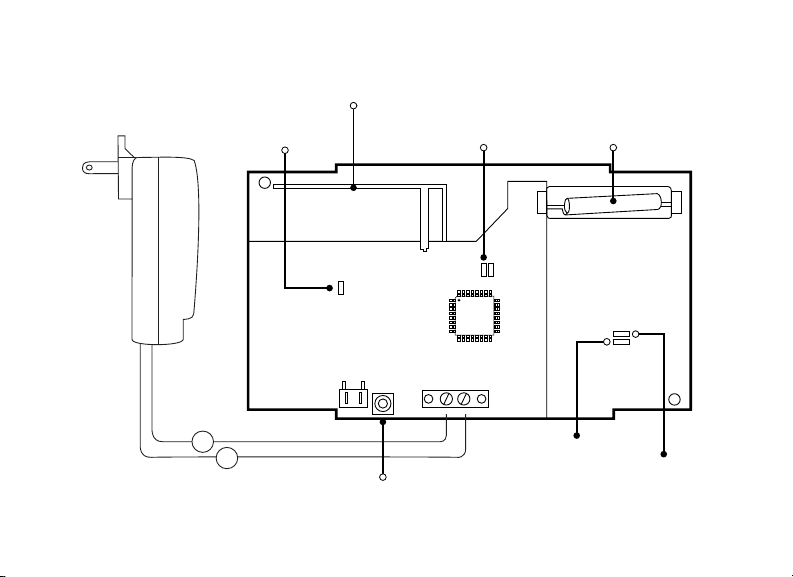
Translator Features ....................................3
Pre-Installation ...........................................4
Install the Translator ..................................4
Wire the Power Supply ..................................... 4
Program Device Setup ..................................... 5
Select a Location for the Translator............. 6
Program Zone Information.............................. 6
Mount the Translator.......................................... 8
Walk Test................................................................. 9
Additional Information ............................. 11
Replace the Battery............................................11
Status LEDs ...........................................................11
Non-DMP Sensor Supervision Time ............12
1100T Supported Zones ...................................12
TABLE OF CONTENTS
Compliance Listing Specifications ........ 13
Commercial Fire..................................................13
Product Specifications ............................ 14
Patents ....................................................... 14
Accessories................................................ 15
Certifications............................................. 15
Intertek (ETL Listed).........................................15


Digital Monitoring Products, Inc. | 1100T Wireless Translator Installation and Programming Guide 1
The 1100T Wireless Translator allows upgrades of non-DMP systems with one way, low
frequency, wireless transmitters to DMP. The 1100T is compatible with transmitters that
operate at various MHz such as Interlogix, Honeywell 5800, 2GIG, and DSC.
The translator operates with a wireless connection to a receiver on a DMP panel.
Learn Feature
Transmitters that have been learned into
the 1100T are able to send supervision and
low battery messages to the panel.
Tampers
The translator is equipped with a case and
wall tamper.
ABOUT THE TRANSLATOR

2 1100T Wireless Translator Installation and Programming Guide | Digital Monitoring Products, Inc.
Compatibility
• All DMP XT Series panels and XR Series panels with version 211 or higher
• All 1100 Series Wireless Receivers with versions 207 or higher—excluding the 1100R
Repeater
Warning: The 1100T Wireless Translator is not compatible with systems using
the 1100R Wireless Repeater.
• Interlogix 319.5 MHz
• Honeywell 5800 345 MHz
• 2GIG Series 345 MHz
• DSC 433 MHz
• Encryption from 1100T to DMP Receiver requires panel Version 211 or higher and
Receiver Version 301 or higher
Full Compatibility Guide
For a full list of compatible non-DMP products, see the 1100T Wireless
Translator Compatibility Guide LT-2430. Scan the QR code below if
viewing this in a printed manual.

Digital Monitoring Products, Inc. | 1100T Wireless Translator Installation and Programming Guide 3
TRANSLATOR FEATURES
Figure 1: Product Features
+BAT- +12V-
-
+
Tamper Switch
Survey LED
MODEL 1100T
Non-DMP
Antenna
DMP Antenna
Charge Status
LED
Green
Status LED Red
Status LED

4 1100T Wireless Translator Installation and Programming Guide | Digital Monitoring Products, Inc.
INSTALL THE TRANSLATOR
Wire the Power Supply
The 1100T Wireless Translator can be powered from a 12 VDC external power supply.
In addition to powering the translator, the power supply also charges the back-up
battery. If the DC power source is removed, the power failure is indicated as an open
condition on the translator device number.
The 372-500-W power supply must be located within 100 feet of the translator using
22 AWG wire. Use the following steps to connect it:
1. With the cover removed, connect the positive wire to the positive terminal on
the translator.
2. Connect the negative wire to the negative terminal on the translator.
3. Plug the power supply into a wall outlet not controlled by a switch.
1
PRE-INSTALLATION
Before installing the translator, the DMP panel and receiver must already be powered on
and set up in their final locations. See the panel and receiver guides for their installation
information.

Digital Monitoring Products, Inc. | 1100T Wireless Translator Installation and Programming Guide 5
Program Device Setup
The translator must first be programmed as a device in Device Setup. Zones should
be programmed in Zone Information.
1. Go to DEVICE SETUP and press CMD.
2. At DEVICE NO, enter the desired device number for the 1100T. Available addresses:
• XT30, XT50, XTL Series, or XR150: 2-8
• XR550: 2-16
3. Select *UNUSED* to enter a name for the device. After naming the device,
press CMD.
• XR Series Panels:
Press the fourth select key or area to change the device type.
Press CMD until TLR is displayed and select that for the translator.
• XT Series Panels:
At 1100T? NO YES, select YES and press CMD.
4. Enter the Serial number.
5. At 1100T FREQ, press any select key or area to select the non-DMP system.
Default is HWL (Honeywell).
6. At SUPRVSN TIME, select the supervision time required for the 1100T. DMP
default supervision time is 240 minutes.
7. Press CMD and then the Back Arrow to exit Device Setup.
2

6 1100T Wireless Translator Installation and Programming Guide | Digital Monitoring Products, Inc.
Select a Location for the Translator
The 1100T translator provides a Survey LED capability to allow one person to confirm
communication with the panel while the cover is removed.
1. While remaining in panel programming, hold the translator in the exact
desired location.
2. Press the tamper switch to send data to the panel and determine if
communication is confirmed or faulty.
Confirmed: If communication is confirmed, for each press or release of
the tamper switch, the LED blinks immediately on and immediately o.
Repeat this test 5 times to confirm ten separate consecutive LED
blinks. Any indication otherwise means proper communication has not
been established.
Faulty: If communication is faulty, the LED remains on for about 8
seconds or flashes multiple times in quick succession. Relocate the
translator or receiver until the LED confirms clear communication.
3
Program Zone Information
1. In ZONE INFORMATION, enter the wireless zone number.
2. At *UNUSED*, enter the zone name.
3. Select a ZONE TYPE.
4

Digital Monitoring Products, Inc. | 1100T Wireless Translator Installation and Programming Guide 7
4. At DMP WIRELESS, select NO.
5. At COMP WLS, select YES.
6. At COMP WLS SRL #, either manually enter the serial number of the transmitter or
transmit the serial number to the panel:
• Manually: Press the first select key or area and type in the transmitter’s
serial number.
• Transmit: Choose LRN at prompt to display TRANSMIT NOW. Tamper
the transmitter. Once the panel has received the tamper signal, the
serial number will display.
Note: If programming a sensor with multiple contacts, use the
appropriate serial number. See LT-0705 1114 Wireless Four-Zone
Expander Installation Guide for programming instructions.
7. Once the serial number is entered, press CMD.
8. At the transmitter contact display, press a select key to choose from contact 1,
2, 3, or 4. Default is 1.
Note: If programming a sensor with one contact, leave the transmitter
contact option at the default.
9. At the transmitter supervision time, press a select key to choose from 0H, 4H
(if zone type is FI, CO, or SUPV), 12H, or 24H. Default is 24H.
10. Save and exit programming.

8 1100T Wireless Translator Installation and Programming Guide | Digital Monitoring Products, Inc.
Mount the Translator
The translator must be mounted using the provided #6 screws in the four mounting
holes. Mount the translator in a secure, dry place away from metal objects to protect
the unit from damage due to tampering or the elements. Mount the translator a
minimum of 4 feet from any wireless panels or receivers. It is necessary to remove the
PCB when installing the enclosure. Refer to Figure 2 in the following steps.
1. With the cover
removed, use the
included #6 screws to
secure the 1100T to
the wall.
2. Use one of the
provided screws
to secure the wall
tamper.
5
Figure 2: Inside of the 1100T Housing
Tamper Puck
Mounting Hole

Digital Monitoring Products, Inc. | 1100T Wireless Translator Installation and Programming Guide 9
Walk Test
To test the system, perform a standard walk test. Non-DMP wireless devices are not
compatible with the DMP Wireless Walk Test. See the panel programming guides for
more information.
XR Series Panels
1. Reset the control panel by placing and removing a jumper on RESET.
2. At the keypad, enter 8144 (WALK).
3. Select the zone type you want to test. An asterisk indicates the chosen zone
type. Press the select key or area again to deselect the zone type. When you
have selected all the zone types you want for testing, press CMD.
Note: For the purpose of the Walk Test, do not select WLS or PIR. These
options are not compatible.
4. Select BELL. This option is for when a zone under test faults. This option
allows the panel bell, and/or burglary bell, and/or fire bell to turn on and then
o each time a zone is tripped.
• NO - Select for no bell output action during Walk Test.
• YES - Select to turn on any bell output for 2 seconds during Walk Test.
• PULS - Select to turn on any bell output for 1/4 second during Walk Test.
5. Once in the Walk Test, walk around and trip each protective device. Continue
tripping devices until the entire system is tested.
6. Press the select key or area directly below END to stop the Walk Test.
6

10 1100T Wireless Translator Installation and Programming Guide | Digital Monitoring Products, Inc.
XT Series Panels
1. Reset the control panel by placing and removing a jumper on RESET.
2. From the keypad, enter 8144 (WALK).
3. Select STD to test all programmed zones.
4. Once in the Walk Test, walk around and trip each protective device. Continue
tripping devices until the entire system is tested.
• Each time a selected zone trips, the keypad buzzes and the bell rings
for two seconds.
• Each time a FI, FV, SV, or CO zone trips, a Sensor Reset occurs.
5. Press the select key or area directly below END to stop the Walk Test.

Digital Monitoring Products, Inc. | 1100T Wireless Translator Installation and Programming Guide 11
ADDITIONAL INFORMATION
Replace the Battery
1. Open the translator housing to expose the inside of the 1100T.
2. Remove the PCB board
3. Unplug the battery connector, then remove the old battery
4. Connect the battery connector
5. Snap the PCB Board back in place.
6. Snap the cover back on the 1100T.
Status LEDs
The green and red status LEDs in the lower right corner of the 1100T provide visual
indication of DMP 1100 wireless synchronization status.
• Green ON and red OFF indicates the 1100T is in sync with the DMP 1100 wireless
receiver.
• Green OFF and red ON means the 1100T is not in sync with the receiver.
• If the green is OFF and red flashes every 1/4 second, the 1100T should be power
cycled manually.
The charge status LED is hardware controlled and will be ON when the battery is
connected and charging. It will be OFF when the battery is connected and fully charged.
Flashing once a second indicates a charge controller fault which will occur if the battery is
disconnected.

12 1100T Wireless Translator Installation and Programming Guide | Digital Monitoring Products, Inc.
1100T Supported Zones
The supported zones per DMP panel are as follows:
DMP PANEL AVAILABLE ZONES ZONE RANGES
XTLplus and XTLtouch 99 1 - 99
XT50 with built-in receiver 48 11 - 14, 21 - 24, 31 - 34, 41 - 44, 51 - 54, 61 - 64, 71 - 74, 81 - 84, 80, 85 - 99
XT30 and XT50 (1100D Series) 32 11 - 14, 21 - 24, 31 - 34, 41 - 44, 51 - 54, 61 - 64, 71 - 74, 81 - 84
XR150 (1100X Series) 100 500 - 599
XR550 (1100X Series) 128 Any unused zone between 500 and 999
Non-DMP Sensor Supervision Time
Default Supervision time for Non-DMP sensors is 24 Hours. Additional supervision times
available include:
• 0 H
• 4 H - Fire, CO, or Supervisory zone type
• 12 H
Follow manufacturer guidelines for supervision times required on non-DMP sensors.

Digital Monitoring Products, Inc. | 1100T Wireless Translator Installation and Programming Guide 13
COMPLIANCE LISTING SPECIFICATIONS
Commercial Fire
Power Supply
When using the Model 372-500-W plug-
in power supply for Commercial Fire
installations, mount the 1100T on a UL-
listed gangbox and connect by conduit to
a listed transformer enclosure such as the
ES501 or ES502.
Install the enclosure by removing the two
screws from the outlet and inserting them
through the back of the enclosure. Install
conduit fittings, connect wiring, and install
the power supply. Secure the enclosure
cover with two screws. See Figure 3.
Battery
The 9800BAT2400 provides 24-hour
standby operation for Commercial Fire
installations.
Install in accordance with NFPA 70 and
NFPA 72 Chapter 29.
Conduit
ES501
372-500-W
1100T installed on backbox
Figure 3: Power Supply
with Enclosure Wiring

14 1100T Wireless Translator Installation and Programming Guide | Digital Monitoring Products, Inc.
PRODUCT SPECIFICATIONS
Operating Voltage 12 VDC, 31 mA
Standby Battery
Voltage 3.7 VDC
Capacity 800 mAh, 2400 mAh
Type Lithium Polymer, rechargeable
Standby 4 hours, 24 hours
Frequency Range 905-924 MHz
Dimensions 5.50” W x 3.75” H x 1.00” D
13.97cm W x 9.53 cm H x 2.54 cm D
Temperature 32 ° - 120 ° F
Humidity 93%
PATENTS
U.S Patent No. 7,239,236 DMP Wireless Sensors

Digital Monitoring Products, Inc. | 1100T Wireless Translator Installation and Programming Guide 15
CERTIFICATIONS
FCC ID: CCKPC0225
IC: 5251A-PC0225
Intertek (ETL Listed)
UL 864 Control Units and Accessories for Fire Alarm Systems
UL 985 Household Fire Warning System
UL 1023 Household Burglar Alarm System Units
UL 2610 Commercial Premises Security Alarm Units and Systems
ACCESSORIES
1100RBAT800/8 Replacement rechargeable battery (8 pack)
9800BAT2400/8 Battery for Commercial Fire
505-12 12 VDC Power Supply
372-500-W Plug-In DC Power Supply
ES501 Transformer Enclosure
ES502 Transformer Enclosure

16 1100T Wireless Translator Installation and Programming Guide | Digital Monitoring Products, Inc.
FCC INFORMATION
This device complies with Part 15 of the FCC Rules. Operation is subject to the following two conditions:
1. This device may not cause harmful interference, and
2. This device must accept any interference received, including interference that may cause
undesired operation.
Changes or modifications made by the user and not expressly approved by the party responsible for
compliance could void the user’s authority to operate the equipment.
Note: This equipment has been tested and found to comply with the limits for a Class B digital
device, pursuant to part 15 of the FCC Rules. These limits are designed to provide reasonable
protection against harmful interference in a residential installation. This equipment generates,
uses and can radiate radio frequency energy and, if not installed and used in accordance with
the instructions, may cause harmful interference to radio communications. However, there is
no guarantee that interference will not occur in a particular installation. If this equipment does
cause harmful interference to radio or television reception, which can be determined by turning
the equipment o and on, the user is encouraged to try to correct the interference by one or
more of the following measures:
• Reorient or relocate the receiving antenna.
• Increase the separation between the equipment and receiver.
• Connect the equipment into an outlet on a circuit dierent from that to which the receiver
is connected.
• Consult the dealer or an experienced radio/TV technician for help.
Other manuals for 1100T
1
Table of contents
Other DMP Electronics Electronic Dictionary manuals
Popular Electronic Dictionary manuals by other brands

Sennetech
Sennetech SCT-CTX-Pelco-Panasonic v20 Quick user guide

Franklin
Franklin SCD-787 user guide

Franklin
Franklin Talking Children's Dictionary KID-1240 user guide

Franklin
Franklin Central European Translator TCE-100 user guide

Resolution Products
Resolution Products RE320 quick start guide

Franklin
Franklin HR-61 user manual