7700 MultiFrame Manual
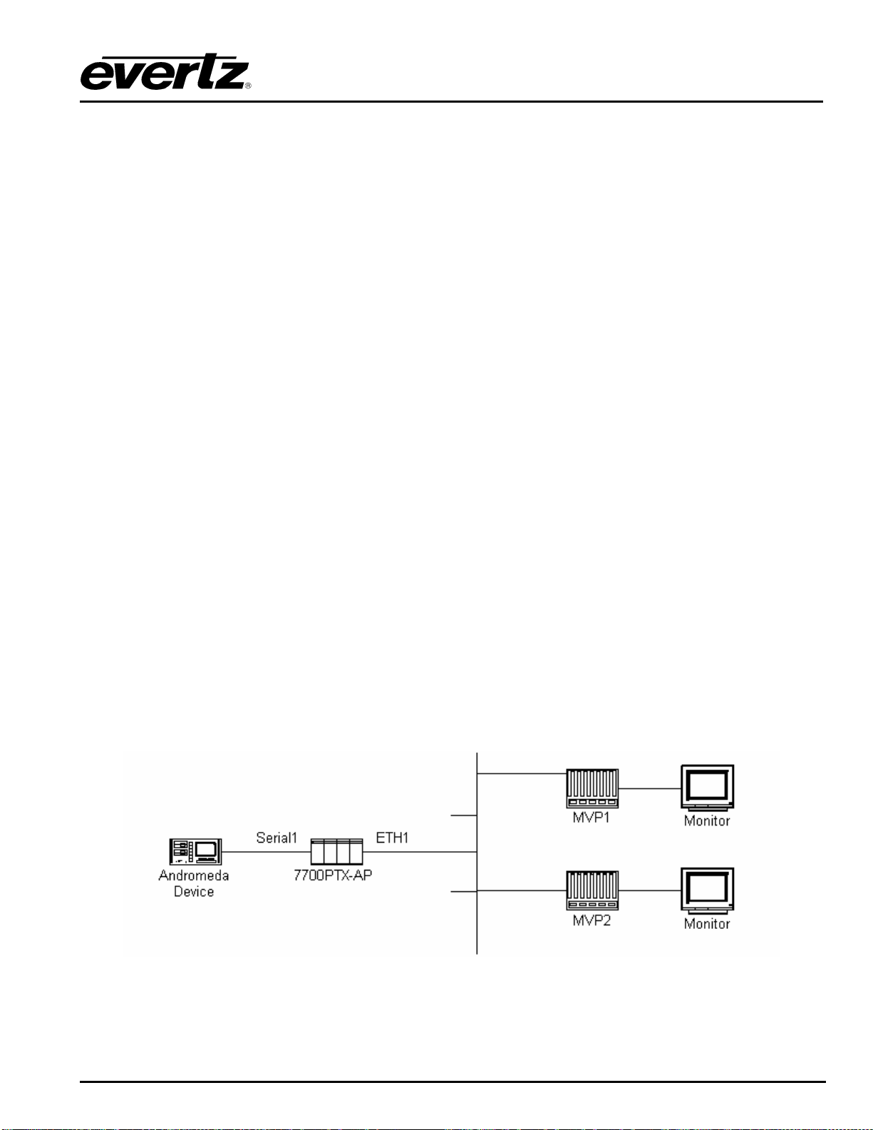
7700PTX-AP ASCII Plus Protocol Translator
Revision 1.7
TABLE OF CONTENTS
1. OVERVIEW..................................................................................................................................... 1
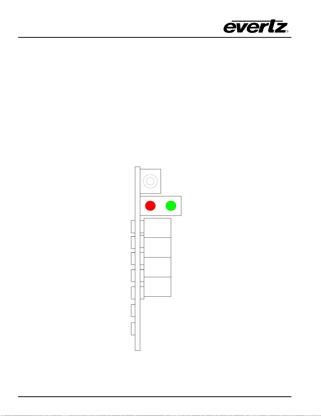
2. CARD EDGE CONTROLS..............................................................................................................2
2.1. DETERMINING CURRENT IP ADDRESS SETTINGS.......................................................... 2
2.2. RESTORING FACTORY DEFAULTS.................................................................................... 2
2.3. CARD EDGE LEDS ............................................................................................................... 2
3. TECHNICAL SPECIFICATIONS..................................................................................................... 3
3.1. DATA INPUT SERIAL PORT.................................................................................................3
3.2. ELECTRICAL......................................................................................................................... 3
3.3. PHYSICAL ............................................................................................................................. 3
4. CONFIGURATION.......................................................................................................................... 4
4.1. CONFIGURATION STEPS .................................................................................................... 4
4.2. DEBUG/MONITOR PORT CONNECTION............................................................................. 4
4.3. MAIN MENU........................................................................................................................... 6
4.4. NETWORK CONFIGURATION.............................................................................................. 6
4.5. SERIAL PORT SETUP ..........................................................................................................7
4.5.1. Parameters .................................................................................................................7
4.5.2. Back Plate................................................................................................................... 8
4.5.3. RS-232 Wiring............................................................................................................. 9
4.5.4. RS-422 Wiring........................................................................................................... 10
4.6. ASCII PLUS PROTOCOL SETUP....................................................................................... 11
4.6.1. Supported Commands..............................................................................................11
4.6.2. UMD Mapping...........................................................................................................11
4.6.3. Tally Mapping............................................................................................................ 11
4.6.4. User Defined Display Mode......................................................................................11
4.6.5. Display ID Offset.......................................................................................................12
4.6.6. AP Address 0xFE Remap To 00............................................................................... 12
4.7. UNDER MONITOR DISPLAY SETUP ................................................................................. 12
5. TROUBLESHOOTING TIPS......................................................................................................... 13
5.1. CHECKING ANDROMEDA COMMUNICATION ................................................................. 13
5.2. CHECKING UMD COMMUNICATION................................................................................. 14
6. PERFORMING A FIRMWARE UPGRADE................................................................................... 15
6.1. FTP PROCEDURE............................................................................................................... 15
6.2. SERIAL PROCEDURE ........................................................................................................ 15