manuals.online logo
Brands
  1. Home
  2. •
  3. Brands
  4. •
  5. DMQ
  6. •
  7. Measuring Instrument
  8. •
  9. DMQ QS3 Series User manual

DMQ QS3 Series User manual

I
P/N: QSD 301 –ENG –Rev 3 –2012
I
Chapter 1
First Steps
1.1
Know the QS5
1
1.1.1
Front panel
1
1.1.2
Connectors
2
1.2
Install or replace batteries
3
1.3
Connecting the transducer
5
1.4
The “Q” key
6
1.5
Display illumination and contrast
6
1.5.1
Display backlight illumination
6
1.5.2
Display contrast
7
1.6
Locking and unlocking the keypad
7
Chapter 2
Measuring with the QS3
2.1
Measuring screen
9
2.2
Keys in the measuring screen
10
2.3
Zero calibration (Auto)
12
2.4
Changing the material velocity
13
2.4.1
Change to a known velocity
13
2.4.2
Change velocity using a known
thickness value
13
Chapter 3
Menu system and editing
3.1
Instructions on using the menu system
15
3.2
Main menu
16
3.3
Change measuring unit
16
3.4
Alarm settings
17
3.5
Memory Menu
18
3.5.1
Connecting to a PC with DataCenter
18
3.5.2
View data
19
3.5.3
Erase memory
20
3.5.4
Capture modes
21
3.5.5
Free memory
21
II
3.6
General configuration options
22
3.6.1
Select language
22
3.6.2
Set keypad sensitivity
23
3.6.3
Adjust gain
24
3.6.4
Set auto-off time
24
3.6.5
Adjust display contrast
25
3.6.6
Beep activation
25
3.6.7
Hold last value
26
3.6.8
Unit information
26
Tips on how to measure correctly
Technical specifications
Additional information
Unit maintenance
QS3 accessories
Error messages
Our website: www.demeq.com
Technical support
III
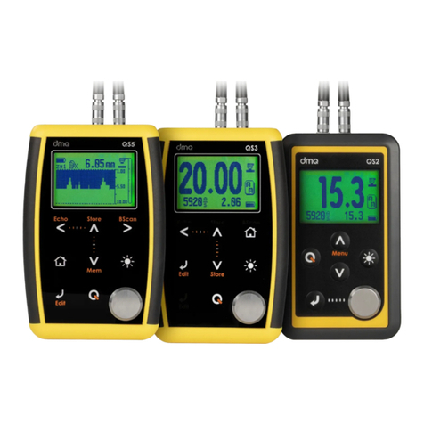
And thank you for purchasing a QS3 ultrasonic wall thickness gauge.
At dmq we develop, manufacture and distribute software and quality
control instruments offering innovation and solutions that come as a
direct result of listening to your needs as a user. We apply some of the
latest technology available in the industry to build instruments that are
robust, precise, and easy to operate.
We are convinced that our products would not be complete without
permanent technical and after sales support. So in addition to a great
product we offer:
Quick answers to your inquiries.
Unlimited access to technical information as well as
application notes.
Special offers for registered customers.
Firmware and software upgrades at no charge.
Attention to your inquiries and suggestions.
We hope that the QS3 will meet and exceed your application needs.
IV
The information included in this manual applies to all QS3 series
ultrasonic wall thickness gauges including models B and DL.
dmq is a registered trademark of demeq S.R.L and its affiliate
companies.
The information contained in this manual is intended to educate users
on the operation of the QS3 gauges. Failure to read and understand
this manual can lead to measurement errors. Decisions based on
measurements and or results that are erroneous can lead to property
damage, personal injury or even death. Demeq S.R.L assumes no
responsibility as a result of the improper use of our instruments.
ASTM E797
The user must be trained in ultrasonic testing procedures and on how
to properly configure the unit for testing. All of the following should
be taken into consideration:
Understand the theory on sound wave propagation.
Select the instrument as well as the transducer that is best
suited for your application.
Know the specific requirements for the test you will be
conducting.
This manual provides all of the information needed to configure and
operate the QS3 gauge. However there are additional factors that can
V
affect tests done with this instrument. Specific information on those
factors is outside the scope of this manual. When in doubt you should
always seek expert advice or refer to specific textbooks on ultrasonic
testing. Additional information can also be found on the internet and
through local government agencies as well as in technical institutes.
The QS3 operates with dual crystal transducers that use the “pitch-
catch” principal. Dual crystal transducers use two piezoelectric crystals
whereby one crystal is excited with short electrical pulses from the unit
sending short acoustic waves into the test piece. The second crystal
then receives the acoustic waves reflected at the end of the test piece.
The frequency of the acoustic waves changes between 2 and 10 MHz
depending on the probe being used.
Figure 1: Transducer acoustic wave representations
VI
In ultrasonic testing information is obtained from measuring sound
waves. Users must be very careful when making assumptions in
regards to the entire test piece condition when there are areas that
have not been inspected. In large and massive test pieces it would be
practically impossible to test the entire piece and therefore conclusions
for the whole piece based solely on the areas that have actually been
inspected, should only be done by experienced operators. Only trained
users should evaluate test pieces that could present erosion and or
corrosion.
In order to minimize test result errors the following must be observed:
Before taking actual measurements the unit and transducer have to be
calibrated. Calibration of the transducer is also known as zero
calibration or delay calibration (Page 12). If the unit and transducer are
not calibrated, or calibrated incorrectly, the resulting measurements
will be unreliable. Each and every time a transducer is changed it must
be calibrated to the unit.
Because the sound velocities in materials will often vary significantly
from published values, best results are obtained when the instrument
is calibrated on a reference test block made from the same material as
that of the actual test piece. The block should be flat, of a smooth
finish, and be as thick as the maximum thickness of the test piece.
Careful consideration by the user must be made when evaluating the
accuracy of a thickness value because considerable changes in the
sound velocity of a material may have occurred as a result of a
treatment. So for example a test piece made of steel that has been
thermally treated, will look the same as a regular test piece made of
VII
untreated steel, but the sound velocities vary significantly. Instruments
should be calibrated before and after testing to minimize errors.
Transducers must be in good condition and show no visible signs of
excessive wear or defects on their surface. Badly worn transducers can
provide erroneous measurements.
The thickness of the material being tested must be within the specified
thickness range of the transducer and the temperature of the material
must also be within the specified temperature range of the transducer.
Calibration as well as actual testing should be performed under similar
coupling conditions. Couplant must be applied in an even and
consistent manner to minimize variations in couplant layers that may
result in testing errors. The amount of couplant should be kept to a
minimum and consistent pressure should be applied on the transducer
when measuring.
Doubling refers to a thickness measurement that displays a reading
that is twice or even three times the real test piece thickness. Doubling
often may happen when trying to measure below and above the
specified range for the transducer and when using worn transducers.
When in doubt, the test piece thickness must be measured using other
methods and or instruments and the unit must then be calibrated
using reference test blocks of known thickness values that are made of
the same material as the actual test piece. This is very important when
measuring unknown test pieces for the first time.
When possible calibrate your instrument on-site using a test block that
is at the same temperature as the test piece in order to minimize
errors.
VIII
QS3 series thickness gauges are for industrial use only and cannot be
used in medical applications. The QS3 operates on two AA size
batteries. We strongly recommend that you use only top brand name
alkaline batteries.
Disposal of your QS3 gauge and its components must be done in
compliance with all applicable regulations.
Because of its complexity level, software is never really completely error
free. For this reason in software controlled instruments always make
sure that the operations required for your application are in correct
working order.
Demeq S.R.L provides a limited warranty for a period of 2 (two) years
on electronic units and for 6 (six) months on transducers from the date
of purchase and may be extended for up to 5 years.
Every instrument undergoes thorough testing during manufacturing as
well as before shipping. In the event warranty service where to become
necessary, dmq and or your local distributor or representative will
make a reasonable effort to replace your defective unit with another
new or used unit, while your instrument undergoes warranty repair.
Chapter 1 1
Figure 1.1: Front of the unit
1. Graphic LCD display with LED backlight illumination
2. Move Left key
3. Move Up key
4. Menu key / Enter and exit measure screen / Exit and return to
menus (Home)
5. Enter key / Edit values on the measure screen (Edit)
6. Move Down key / Quick access to memory menu screen
options (Mem)
2 Chapter 1
7. Change backlight illumination key (On, Off, Auto)
8. The key: Power On and Shutdown (touch and hold for 2
seconds) / Make quick and short touches to activate special
functions and features
9. Calibration disk
10. Horizontal scrolling center point (lock and unlock keypad on
measure screen)
11. Vertical scrolling center point (adjust LCD contrast)
Figure 1.2: Unit connectors
1. Receiving transducer connector (Type Lemo 00)
2. Emitting transducer connector (Type Lemo 00)
3. USB mini connector to connect to PC using a USB cable (QS3
DL only)
Chapter 1 3
The QS3 is powered by 2 (two) AA batteries that are placed in the
battery compartment located in the back of the unit. To gain access to
the battery compartment slide the cover as shown in figure 1.3-1 and
gently push the extraction ribbon upward and slightly towards the
right to release the batteries (figure 1.3-2).
When you install new batteries, first insert the positive end of each
battery so that it coincides with the positive pole inside the battery
compartment as you see in figure 1.4-1. Always leave the extraction
ribbon underneath the batteries.
Figure 1.3: Removing batteries
4 Chapter 1
Figure 1.4: Replace / Insert batteries
Notes
Use new alkaline top brand batteries only.
Do not mix new and old batteries. Always replace both
batteries.
Rechargeable batteries type NiMH can be used but will
result in less time of continuous operation.
Chapter 1 5
Important
Do not remove batteries while the unit is powered as
this may affect the Data Logger (See Apendix:
“Additional information, Error Messages”)
The QS3 has two type Lemo “00” connectors located on top of the
unit. Because this is the standard for most dual crystal probes, you
could basically connect any probe to your QS3. Keep in mind that the
gain may need to be adjusted when changing probes.
To connect the probe, simply align any
of the male connectors located at the
end of the transducer cable to any of
the female connectors located on the
gauge and press gently until
connected.
To release the probe hold the knurled
section on the male connectors and
pull gently away from gauge until
released.
Figure 1.5: Connecting the transducer
6 Chapter 1
The has three functions:
1. When the unit is off, touch for 2 seconds to power on
the unit.
2. When the unit is on, touch for 2 seconds to shutdown
the unit.
3. With the unit on, making short touches to the will
activate special functions described in each chapter of this
manual.
Backlight illumination and contrast options can be changed from any
screen in the unit.
Touch to change the backlight illumination.
Figure 1.6: Backlight illumination options
Chapter 1 7
When you touch the white dot located in the
center of the vertical scrolling bar between the
- keys a contrast window will open.
Move your finger towards the top and or bottom
of the dotted line to adjust the contrast on your
display.
Figure 1.7: Display contrast adjustment
To lock the keypad place your finger on the white dot located in the
center of the horizontal scrolling bar between the - keys.
Move your finger to the right following the dotted line and a window
on the unit display will open with the word Lock. Continue moving
your finger in the same direction until you enter locked mode. The
window on the display will close and the locked keypad indicator will
show on the top right corner of the unit screen.
Figure 1.8: Locking the keypad
8 Chapter 1
Sliding the finger to the left will unlock the keypad.
Figure 1.9: Unlocking the keypad
\
Important
The keypad can only be locked and unlocked in the
measuring screen.
Chapter 1 9
The QS3 measuring screen is represented below:
Figure 2.1: Measuring screen
1. Icon indicating that a value was stored
2. Locked keypad icon indicator (Page 7)
3. Inactive calibration disk indicator (Page 12)
4. Coupling indicator
5. Measuring unit
6. Battery level indicator
7. Minimum measured value (set to zero touching )
8. Thickness value in the selected unit
9. Material velocity
10 Chapter 2
Keypad functionality:
: Touch to exit the measuring screen and enter the main menu.
: Touch to manually store the measurement in the memory.
: Touch to activate the Select / Edit mode. Flashing arrows will
appear over the fields of material velocity and measurement.
Touch to select thickness
measurement.
Touch to select material
velocity.
Figure 2.2: Measuring screen in select / edit mode
Always use the - keys to edit the values in any given field and
touch to save.
Note
The measurement field can only be edited if an actual
measurement was taken. If the measurement is 0.00 this
field cannot be edited.

This manual suits for next models

2

Other DMQ Measuring Instrument manuals

DMQ QSV-B User manual

DMQ

DMQ QSV-B User manual

DMQ QS5 Series User manual

DMQ

DMQ QS5 Series User manual

DMQ QC Series User manual

DMQ

DMQ QC Series User manual

DMQ QB7 User manual

DMQ

DMQ QB7 User manual

DMQ QC5 Series User manual

DMQ

DMQ QC5 Series User manual

Popular Measuring Instrument manuals by other brands

MSV MINI STT Operating	 instruction

MSV

MSV MINI STT Operating instruction

Agilent Technologies E5071C Service guide

Agilent Technologies

Agilent Technologies E5071C Service guide

YOKOGAWA GS820 user manual

YOKOGAWA

YOKOGAWA GS820 user manual

Dakota Digital VHX-67C-CAM-K-B Installation and operation manual

Dakota Digital

Dakota Digital VHX-67C-CAM-K-B Installation and operation manual

Preventice Solutions IMD Post Event Patient Instruction Manual

Preventice Solutions

Preventice Solutions IMD Post Event Patient Instruction Manual

Heinz Walz IMAGING-PAM Instrument description and information for users

Heinz Walz

Heinz Walz IMAGING-PAM Instrument description and information for users

Nibe EMK 500 Installer manual

Nibe

Nibe EMK 500 Installer manual

Teradek TOF.1 quick start guide

Teradek

Teradek TOF.1 quick start guide

R-Biopharm RIDA CUBE SCAN user manual

R-Biopharm

R-Biopharm RIDA CUBE SCAN user manual

ThermoWorks ThermaQ WiFi quick start guide

ThermoWorks

ThermoWorks ThermaQ WiFi quick start guide

AXIOMA METERING UAB QALCOSONIC E2 Technical description, installation and user instructions

AXIOMA METERING UAB

AXIOMA METERING UAB QALCOSONIC E2 Technical description, installation and user instructions

Topcon RL-SV2S instruction manual

Topcon

Topcon RL-SV2S instruction manual

CEM SMART System 5 Operation manual

CEM

CEM SMART System 5 Operation manual

Auper Eclipse ID S3 Quick user guide

Auper

Auper Eclipse ID S3 Quick user guide

Steinberg Systems SBS-MT-100 user manual

Steinberg Systems

Steinberg Systems SBS-MT-100 user manual

Purkeys Status 12 Volt installation guide

Purkeys

Purkeys Status 12 Volt installation guide

Lumel N43 User Manual & Quick Start

Lumel

Lumel N43 User Manual & Quick Start

Dräger Alcotest 6000 Instructions for use

Dräger

Dräger Alcotest 6000 Instructions for use

manuals.online logo
manuals.online logoBrands
  • About & Mission
  • Contact us
  • Privacy Policy
  • Terms and Conditions

Copyright 2025 Manuals.Online. All Rights Reserved.