714-8/16 AND 715-8/16 ZONE EXPANDERS
Installation Guide
DESCRIPTION
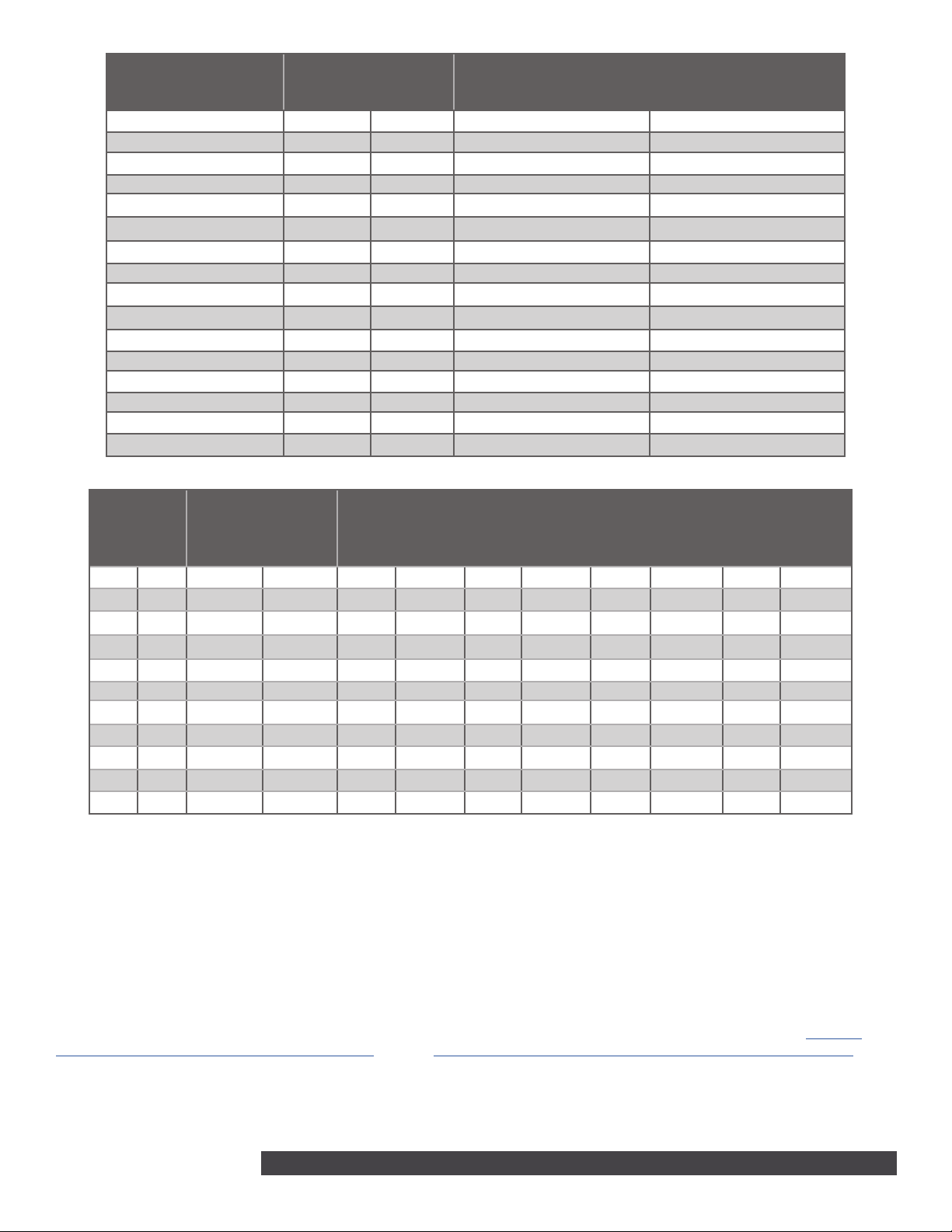
TXD
KYPD LX
Z13+
Z13-
Z14+
Z14-
Z15+
Z15-
Z16+
Z16-
Z9+
Z9-
Z10+
Z10-
Z11+
Z11-
Z12+
Z12-
Z5+
Z5-
Z6+
Z6-
Z7+
Z7-
Z8+
Z8-
Z1+
Z1-
Z2+
Z2-
Z3+
Z3-
Z4+
Z4-
BLK
GRN
YEL
RED
0
1
2
3
4
5
6
7
8
9
0
1
2
3
4
5
6
7
8
9
TENS ONES
TXD
KYPD LX
Z13+
Z13-
Z14+
Z14-
Z15+
Z15-
Z16+
Z16-
Z9+
Z9-
Z10+
Z10-
Z11+
Z11-
Z12+
Z12-
Z5+
Z5-
Z6+
Z6-
Z7+
Z7-
Z8+
Z8-
Z1+
Z1-
Z2+
Z2-
Z3+
Z3-
Z4+
Z4-
BLK
GRN
YEL
RED
0
1
2
3
4
5
6
7
8
9
0
1
2
3
4
5
6
7
8
9
TENS ONES
The 714-8 and 714-16 provide
an additional eight or sixteen
supervised zones for connecting
burglary and nonpowered fire alarm
initiating devices to the panel.
The 715-8 and 715-16 provide an
additional eight or sixteen 12 VDC
ungrounded (Class B) powered
zones for connecting two-wire
smoke detectors.
The zone expanders provide
terminal strips, a jumper for LX-Bus
or Keypad Bus designation, and a
transmit data LED to indicate panel
communication.
All fire device installations
must be in accordance with the
manufacturer instructions, NFPA
standards, and Authority Having
Jurisdiction (AHJ) requirements.
Compatibility
• XT Series Panels and XR Series
Panels
• XF6 Series Fire Control Panels
• 714-8: 1k-4.7k Ohm EOL (Lev E
and higher)
• 714-16: 1k Ohm EOL
• 715-8/715-16: 3.3k Ohm
What is Included?
• One 714-8, 714-16, 715-8, or 715-16
Zone Expander
• Eight or sixteen 1K Ohm Resistors
(714-8/714-16) or 3.3K Ohm
Resistors (715-8/715-16)
• One Model 340 or 350 Enclosure
with Lock and Key
1PROGRAM THE PANEL
After completing each of the following steps, press CMD to
advance to the next option. Refer to the panel programming guide
as needed.
1. Reset the panel and enter 6653 (PROG) at a keypad.
2. In ZONE INFORMATION, program the expansion zones as
any of the panel’s burglary or fire zone types. You can also
program zones as an Arming (AR) zone type when they are
being used with key switches.
3. Press CMD until STOP displays. Press a top row select key or
area to save programming.
MOUNT THE ENCLOSURE
2Mount the enclosure in a secure, dry place. It is not necessary
to remove the zone expander circuit board when installing the
enclosure.
The enclosure can be surface or flush mounted using the holes
provided. Each of the four sides have dual 1/2 in. and 3/4 in.
conduit knockouts for running wires out of the enclosure.
3The zone expanders provide a 3-pin header with jumper used to
select the connection type.
To connect the expander to the Keypad Bus, place the jumper
across the two leftmost pins. To connect the expander to the
LX-Bus, place the jumper across the two rightmost pins. For more
information, refer to Figure 1.
Connect to the LX-Bus
To wire the 714-8/714-16, join the red, yellow, green, and black
wires to a 4-wire harness and connect it to the LX-Bus.
To wire the 715-8/715-16, connect the red wire to panel Terminal 11
(Smoke power terminal). This allows Sensor Reset to drop power
to the module and devices connected to its zones. Join the
yellow, green, and black wires to a 4-wire harness and connect it
to the LX-Bus.
Connect the 714-8/714-16 to the Keypad Bus
1. Connect the red, yellow, green, and black wires to panel
Terminals 7, 8, 9, and 10 respectively.
2. Observe polarity and wire the zones.
3. For 714-8 expanders with hardware Level E or higher,
the expander will read any resistor from 1k-4.7k Ohms
without additional programming. For 714-8 expanders with
hardware Level D or lower and 714-16 expanders, install the
included 1K Ohm EOL resistors.
WIRE THE ZONE EXPANDER