Doepke Dupline DDA 1 User manual

3931250/2014.02/G
Doepke
Dupline
DCF-Aktivantenne DDA 1
für DKG 20 und DKG 21-GSM
(Anwendung in Innenräumen)
DCF-Active Antenna DDA 1
for DKG 20 and DKG 21-GSM
(Indoor use)
Bedienungsanleitung
Operating Instructions

Sollten Sie Fragen zu diesem Produkt oder
zum Dupline-System haben, wenden Sie
sich bitte an:
In case of queries concerning this pro-
duct or the Dupline system please
contact:
Doepke
Schaltgeräte GmbH
Stellmacherstraße 11
D-26506 Norden, Germany
Tel.: +49 (0) 4931/1806-0
Fax: +49 (0) 4931/1806-101 E-mail:
Internet: [email protected]
http://www.doepke.de
23931250/2014.02/G - Technische Änderungen vorbehalten!
Doepke
Inhaltsverzeichnis
1. Allgemeines ......................................................................................................... 3
2. Montage................................................................................................................ 3
3. Inbetriebnahme.................................................................................................... 3
4. Gewährleistung.................................................................................................... 4
5. Technische Daten................................................................................................ 4
6. Maße ..................................................................................................................... 5
7. Anschlussschema............................................................................................... 5
Table of Contents
8. General Information ............................................................................................ 6
9. Installation............................................................................................................ 6
10. Putting into Service............................................................................................. 6
11. Guarantee............................................................................................................. 7
12. Technical Data ..................................................................................................... 7
13. Dimensions .......................................................................................................... 8
14. Connection Diagram ........................................................................................... 8

3931250/2014.02/G - Technische Änderungen vorbehalten! 3
Doepke
Deutsch
1- Inhaltsverzeichnis
Bedienungsanleitung
Dupline DCF-Aktivantenne DDA 1
1. Allgemeines
Die DCF-Aktivantenne DDA 1 ist eine Komponente des Dupline Installationssystems
und ermöglicht den Empfang des hochgenauen DCF77-Zeitsignals, das von der Physi-
kalisch-Technischen Bundesanstalt kontrolliert und in Mainflingen (bei Frankfurt/Main)
ausgestrahlt wird.
Durch Anschluss der DCF-Antenne an die Kanalgeneratoren DKG 20 bzw. DKG 21-
GSM wird deren interne Echtzeituhr mit dem gesendeten DCF-Zeitsignal synchroni-
siert. Somit wird der Abgleich von Datum und Zeit über den PC überflüssig.
Zur Synchronisation von allen DKG 20/DKG 21-GSM in einem Modbus-Netzwerk ist es
ausreichend, den Master mit einer Antenne auszustatten. Letzterer überträgt die syn-
chronisierte Zeit dann automatisch über den RS485-Bus an alle anderen Teilnehmer.
Die Antenne ist für die Wandbefestigung ausgelegt und eignet sich ausschließlich zur
Nutzung in Innenbereichen.
2. Montage
Montieren Sie die Antenne an einer Stelle im Innenbereich, an der ein störungsfreier
Empfang des DCF-Signals gewährleistet ist. Nicht zu empfehlen ist dabei der Einbau in
Metall umschlossenen Verteilern, Kellerräumen und Zimmern ohne Fenster mit Stahl-
betonumgebung.
Vorzugsweise sollte die Antenne waagerecht quer zum DCF-Sender in Mainflingen
(Frankfurt/Main) ausgerichtet sein.
Nach der Inbetriebnahme kann es mehrere Minuten dauern, bis ein gültiges Zeittele-
gramm empfangen wurde. Der Empfang kann durch eine bewusste Verstellung der Zeit
über ProLineNG kontrolliert werden.
3. Inbetriebnahme
Die Inbetriebnahme darf nur von einer autorisierten Fachkraft vorgenommen werden.
Bei der Installation ist das Anschlussschema zu beachten. Alle anzuschließenden Lei-
tungen müssen spannungsfrei sein.
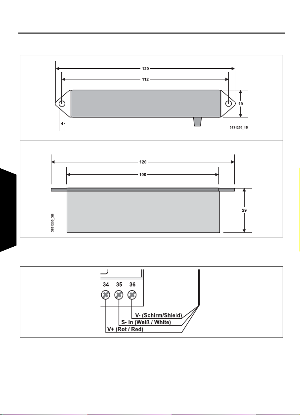
Die verlöteten Litzen des Rundkabels sind folgendermaßen mit den Kanalgeneratoren
DKG 20/DKG 21-GSM zu verbinden:
Ader Beschreibung DKG-Klemme
Rot Spannungsversorgung V+ 34 (V+)
Weiß Antennensignal S- in 35 (S- in)
Schirm Spannungsversorgung V- 36 (V-)

43931250/2014.02/G - Technische Änderungen vorbehalten!
Doepke
Deutsch
4. Gewährleistung
Für fachgerecht montierte, unveränderte Geräte gilt ab Kauf durch den Endverbraucher
die gesetzliche Gewährleistungsfrist. Die Gewährleistung bezieht sich nicht auf Trans-
portschäden sowie Schäden, die durch Kurzschluss, Überlastung oder bestimmungs-
widrigen Gebrauch entstanden sind. Bei Fertigungs- und Materialfehlern, die innerhalb
der Gewährleistungsfrist erkannt werden, leistet unser Werk kostenlos Reparatur oder
Ersatz. Der Gewährleistungsanspruch erlischt, wenn das Gerät unbefugt geöffnet wur-
de.
5. Technische Daten Min. Typ. Max.
Antenne Empfangsfrequenz 77,5 kHz
Eingangsempfindlichkeit 25 µV/m 50 µV/m
Ausgangsspannung 3 V 30 V
Betriebsspannung
Nennbetriebsspannung 2,2 V 15 V
Stromaufnahme 0,6 mA
Anschlüsse 2-adriges Rundkabel mit Schirm, Länge ca. 2,5 m
Gehäuse Graues Kunststoffgehäuse
Allg. technische Daten
Betriebstemperatur 0°C +50°C
Bestellnummer, -bezeichnung 09 501 191, DCF-Aktivantenne DDA 1

3931250/2014.02/G - Technische Änderungen vorbehalten! 5
Doepke
Deutsch
6. Maße
7. Anschlussschema

63931250/2014.02/G - The right to make technical changes reserved!
Doepke
English
1- Table of Contents
Operating Instructions
Dupline DCF-Active Antenna DDA 1
8. General Information
The DCF-active antenna DDA 1 is a component of the Dupline installation system and
enables reception of the extremely precise DCF77 time signal, which in Germany is
controlled by the National Physical Institute and is emitted by the centre in Mainflingen
(near Frankfurt/Main).
By connecting a DCF antenna to DKG 20 or DKG 21-GSM channel generators their in-
ternal real-time clock will be synchronised with the emitted DCF time signal. This obvi-
ates any resetting of date and time via the PC.
To synchronise all DKG 20/DKG 21-GSM generators within a Modbus network all that
is required is to equip the master with an antenna. The latter then automatically trans-
mits the synchronised time via the RS485 bus to all other connected devices.
The antenna is designed for wall mounting and is suited solely for indoor use.
9. Installation
Mount the antenna in a location in the interior where interference-free reception of the
DCF signal is ensured. It is not recommended to install it in a metal-enclosed distributi-
on box, window-less cellars, basements or rooms surrounded by reinforced concrete.
The antenna should preferably be aligned horizontally across to the local DCF emitter.
It may take several minutes after putting into service before a valid time telegram is re-
ceived. Reception can be checked by deliberately setting a wrong time via ProLineNG.
10. Putting into Service
Installation may only be carried out by an authorized trained technician. Follow the con-
nection diagram when installing. All wires to be connected must be dead.
The soldered stranded wires of the round cable should be connected as follows to the
DKG 20/DKG 21-GSM generators:
Wire Description DKG Terminal
Red Voltage supply V+ 34 (V+)
White Antenna signal S- in 35 (S- in)
Screen Voltage supply V- 36 (V-)

3931250/2014.02/G - The right to make technical changes reserved! 7
Doepke
English
11. Guarantee
All professionally installed, unaltered devices are covered by warranty during the statu-
tory guarantee period from the day of purchase by the end user. The guarantee is not
applicable to damage incurred during transport or caused by short-circuit, overloading
or improper use. In the event of defects in workmanship or material, which are discov-
ered within the guarantee period, the company will provide a repair or replacement free
of charge. The guarantee will be rendered null and void if the device is opened without
authorization.
12. Technical Data Min. Typ. Max.
Antenna Incoming frequency 77.5 kHz
Input sensitivity 25 µV/m 50 µV/m
Output voltage 3 V 30 V
Operating Voltage
Rated operating voltage 2.2 V 15 V
Current input 0.6 mA
Connections 2-wire round cable with screen, length approx. 2.5 m
Housing Grey plastic housing
General Technical Data
Operating temperature 0°C +50°C
Order number, description 09 501 191, DCF-active antenna DDA 1

83931250/2014.02/G - The right to make technical changes reserved!
Doepke
English
13. Dimensions
14. Connection Diagram
Table of contents
Languages:
Popular Antenna manuals by other brands

Electro-Metrics
Electro-Metrics LPA-30 instruction manual

NexxTech
NexxTech 1501880 owner's manual

Carbest
Carbest Snipe Handy User instructions

Chameleon Antenna
Chameleon Antenna CHA F-LOOP 3.0 Operator's manual

Alpha Delta
Alpha Delta DX-CC Installation notes

Kompernass
Kompernass KH 2329 operating instructions

zBoost
zBoost YX021-CEL installation manual

Novatel
Novatel GPS-302L-A40 user guide

DX Commander
DX Commander Expedition Antenna KIT user guide

Light Beam Antenna
Light Beam Antenna MaxRange Series Assembly instructions

Ebyte
Ebyte TXWF-FPC-3710 user manual

CommScope
CommScope Cell-Max CMAX-O-TCPUSEWI53 Installation instruction