Dog Guard DG9000 Setup guide

Revised May 2001
Installation & Training Guide

Dog Guard Out-Of-Sight Fencing
Installation and Training Guide
Table of Contents
Installation Guide
A Message from Dog Guard i
Assessing the Yard / Placing Transmitter 1
Equipment 2
Transmitter Installation 3
Procedure for Mounting the Transmitter 4
Grounding the Transmitter 5
Installation of Twisted Pair 7
Wire Loop 9
Direct Burial Splice 13
DG9000 Receiver Collar 14
Assembly of DG9000 Receiver 15
RemoteStrips 16
Shunts 17
AdjustingtheSystem 18
Double Checking the System 19
TroubleshootingTips 20
Helpful Hints for Maintaining Your Dog Guard System 25
Training Guide
TrainingGuidelines 27
EquipmentInformation 28
Training 29
Troubleshooting 32
Taking Your Dog for a Walk: 3 Proven Methods 34
Your Dog Guard Fence 35

The Keenan Building- 258 Broadway, Troy, NY 12180
(518) 687-0030; fax (518) 687-0037
Dear Pet Owner:
Thank you for purchasing a Dog Guard pet containment system. We hope it
brings years of enjoyment and peace of mind for both you and your pet.
In this manual you will find detailed instructions on the entire installation and
training process, from assessing your yard and burying the loop wire to helping
your pet learn his boundaries on the Dog Guard system. We have even included
troubleshooting tips for extra help along the way.
Please note, before beginning installation we recommend consulting your Dog
Guard dealer. Often, many of your installation worries can be eliminated with the
helpful advice of a professionally trained installer.
As you become familiar with the Dog Guard Fencing system and all it has to offer,
you can be confident that we will be behind you every step of the way. In fact,
now that you are part of the Dog Guard family, we will be here for you any time
you need us.
Good luck!
William F. Drew
General Manager

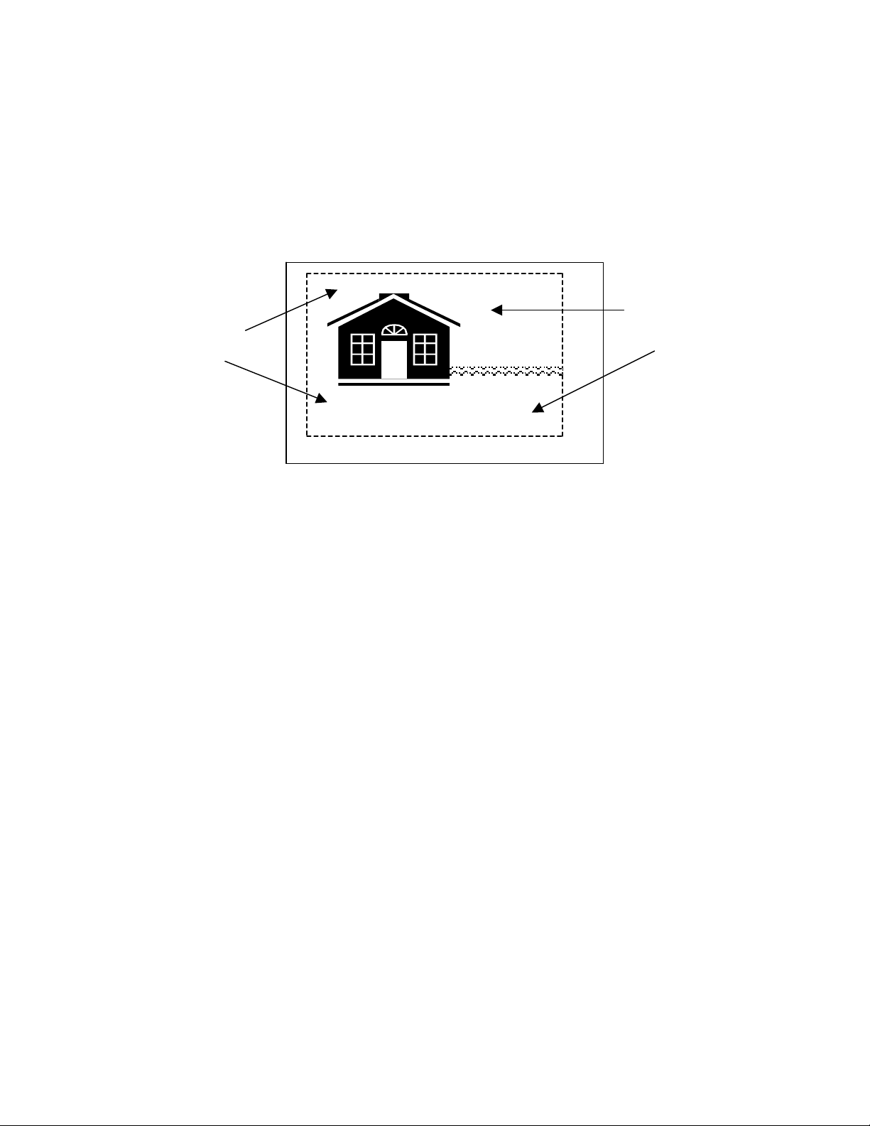
Assessing the Yard
To begin, you must determine where in your yard you want your signal field. This
is the area in which your dog’s receiver collar is activated by a radio signal from
the wire. It extends out 1 – 25 (+) feet on either side of the buried wire. It is
important to leave enough room between the house and the signal field for your
dog to be able to go around the house without running into the signal field.
Wire Loop
Twisted Pair Twisted pair
Containment Area
Where Will You Place the Transmitter?
Because it is not weatherproof, the transmitter should be placed indoors. Most
people find that the garage or basement works best. Be sure to locate it within 6
feet of the 110V electrical outlet into which it will be plugged. Placement must be
at least 10’ from any piping, electrical panel boxes, telephone or TV cable lines.
Try to place the transmitter on the side of the house closest to the wire loop. A
twisted pair of wires that emits no signal must be run from the transmitter to the
wire loop. Remember, the shorter the distance from your transmitter to the loop
wire, the better.
1

Equipment
Your installation will be most successful if you use the following tools:
Wire
• 14 gauge Type USE or Type UF underground rated wire. This wire
provides lifetime durability, resists breakdown and is waterproof.
To Bury Wire
• Gas-powered edger/trimmer or lawn edger
• Flat shovel or ice chopper
To Splice Wire
• Wire splicer or stripper, wire cutters, and splice kit
To Lay Wire Across Gravel Driveways
• Rake (to rake away stones) and shovel (to dig across driveways)
• Old piece of garden hose for wire laid across driveway
To Install Transmitter (mount it on wall, etc.)
• Phillips screwdriver and straight-edge screw driver
• Staple gun (to staple twisted pair wires to walls, etc.) * Careful not to put
staple through wire!
• 3/8” drill bit (to take wire outdoors-through a door frame, window frame, etc.)
• Hammerdrill with 3/8” masonry bit (to go through concrete to bring the twisted
pair from the transmitter to the wire loop)
• Silicone to seal holes (available in tube from hardware store)
To Assemble and Adjust Receiver Collar
• Crescent wrench or small pair of pliers (to tighten probes onto receiver collar)
• Non-permanent Loctite thread locker (used to prevent probes from backing off)
2
Transmitter Installation
The first step in installing the Dog Guard system is putting the transmitter in place.
We recommend installing the transmitter in either the garage or the basement.
• When laying your twisted pair wire, try to make the distance from the
transmitter to the loop wire as short as possible to cut down on line resistance.
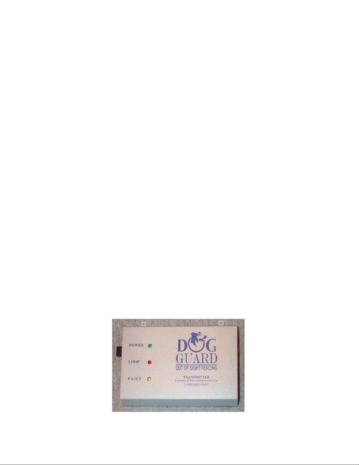
• The INDICATOR LIGHTS on the transmitter should be easily visible from a
distance so that you can quickly see if the unit is operational.
• The GREEN LIGHT lets you know that the unit is on.
• The YELLOW FAULT LIGHT will come on if there is an internal problem
with the transmitter board, i.e.: a lightning hit or power surge.
• The RED LOOP LIGHT indicates that the wire loop is intact.
• Place the transmitter within 6 feet of a 110V electrical outlet.
• The transmitter should be installed at least 10 feet from any existing piping.
Dog Guard’s state-of-the-art transmitter
3

Procedure for Mounting the Transmitter
Dog Guard’s transmitter offers the following mounting options:
OPTION 1 - Mounting Tabs
1. Depending on the surface that you mount your Transmitter on, you will need
that type of screw and/or anchors to hold it in place.
2. Once determined, use two screws to mount the Transmitter to your surface.
OPTION 2 - Velcro
1. To secure the transmitter to the wall, place Velcro strips with adhesive
backings on both transmitter and wall.
4

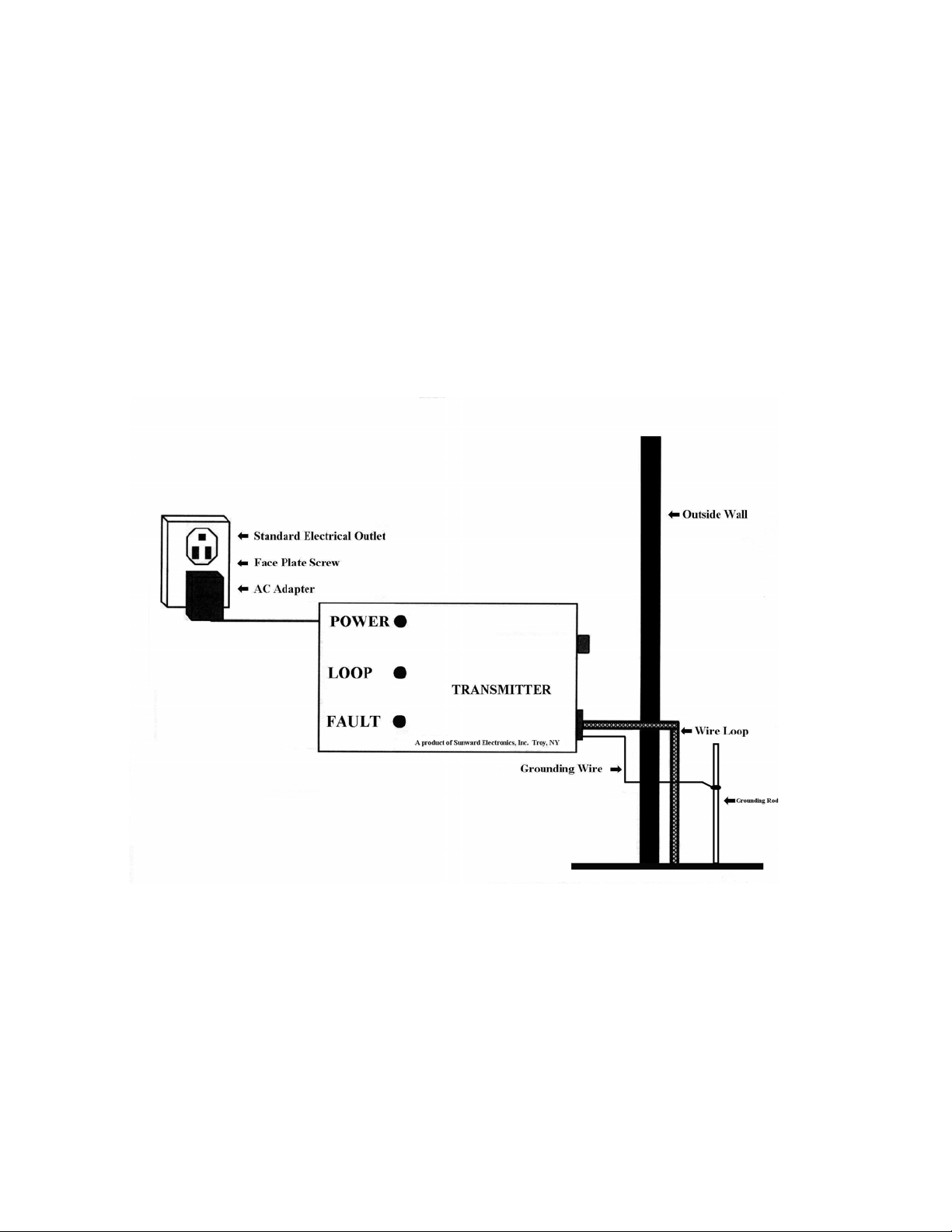
Grounding the Transmitter
An essential step in the installation process, grounding the transmitter protects the
unit against electrical surges and lightning. If possible, locate the transmitter
near an existing grounding device and run a wire to this from the transmitter. For
example, use a spade or lug to attach the ground wire to the outlet faceplate screw.
(See illustration below).
House Grounding Procedure
If the outlet is not grounded you must put an 8’ x ½” copper grounding rod in the
ground and run a wire to it from the transmitter (see illustration on next page).
Dog Guard units that are not grounded void the terms of the warranty.
5
Grounding to a Ground Rod
6
Installation of Twisted Pair
When you run your loop wire, you will cross-areas where you do not want a signal
emitted. To prevent signal emission in these areas, you will twist your wire. This
twisted pair will carry but not emit the signal.
Containment Area
Twisted Pair
Wire Loop
Containment Area
1. Measure the distance of the route the wire must travel from the transmitter to
the outside loop wire.
2. Cut a length of wire approximately 3 to 4 feet longer than the length of this
route from the transmitter to the wire loop.
3. Unroll and cut a second equal length of wire. Have someone hold ends of each
wire or tie as a pair to a stationary object. As you back up from this point,
twist the wires together by hand, or use a hand held drill to twist them together
(10 twists per foot).
4. Hook up the pair to the transmitter. Strip approx. 1/2” from the end of each of
the wires. Open ports for the wire labeled loop with a small screwdriver.
Insert the wires making sure that there are no frays. Close ports onto wires
with the screwdriver
7
This manual suits for next models
1
Table of contents


