Dolmar AS3935 User manual

AS3935
EN Cordless Chain Saw INSTRUCTION MANUAL 8
PL Akumulatorowa Pilarka
Łańcuchowa INSTRUKCJA OBSŁUGI 19
HU Akkumulátoros láncfűrész HASZNÁLATI KÉZIKÖNYV 31
SK Akumulátorová reťazová píla NÁVOD NA OBSLUHU 43
CS Akumulátorová řetězová pila NÁVOD K OBSLUZE 54
UK Бездротова ланцюгова
пила ІНСТРУКЦІЯ З
ЕКСПЛУАТАЦІЇ 65
RO Ferăstrău cu lanţ cu
acumulator MANUAL DE INSTRUCŢIUNI 77
DE Akku-Kettensäge BETRIEBSANLEITUNG 89

Fig.1
2
1
18
3
4
56
11
13
15
12
19
7
81
0
17
9
14
16
Fig.2
1
23
Fig.3
1
2
Fig.4
2

1
2
Fig.5
1
Fig.6
21
Fig.7
2 3
1
23
1
Fig.8
1
Fig.9
1
23
Fig.10
3

1
Fig.11
12
34
Fig.12
1
Fig.13
1
Fig.14
1
2
3
Fig.15
1
Fig.16
12
Fig.17
Fig.18
4

Fig.19
Fig.20
Fig.21
Fig.22
A
B
A
B
Fig.23
Fig.24
2
1
/2
45o
1
45o
Fig.25
1
2
2
33
Fig.26
5

Fig.27
Fig.28
1
2
Fig.29
22
11
31
Fig.30
30
30
55 55
Fig.31
1
2
Fig.32
30
1/5
1
Fig.33
Fig.34
6

Fig.35
Fig.36
2
1
Fig.37
1
2
Fig.38
1 2
Fig.39
7

8ENGLISH
ENGLISH (Original instructions)
SPECIFICATIONS
Model: AS3935
Overall length (without guide bar) 443 mm
Rated voltage D.C. 36 V
Net weight 4.7 - 5.4 kg
Standard guide bar length 350 mm
Recommended guide bar length 300 - 400 mm
Applicable saw chain type
(refer to the table below)
90PX
91PX
Sprocket Number of teeth 6
Pitch 3/8″
Chain speed 0 - 20 m/s
(0 - 1,200 m/min)
Chain oil tank volume 200 cm3
• Duetoourcontinuingprogramofresearchanddevelopment,thespecicationshereinaresubjecttochange
without notice.
• Specicationsmaydifferfromcountrytocountry.
• The weight may differ depending on the attachment(s), including the battery cartridge. The lightest and heavi-
est combination, according to EPTA-Procedure 01/2014, are shown in the table.
Applicable battery cartridge
BL1815N / BL1820 / BL1820B / BL1830 / BL1830B / BL1840 / BL1840B / BL1850 / BL1850B / BL1860B / AP-183
• Some of the battery cartridges listed above may not be available depending on your region of residence.
WARNING: Only use the battery cartridges listed above. Use of any other battery cartridges may cause
injuryand/orre.
Saw chain and guide bar
Saw chain type 90PX
Number of drive links 46 52 56
Guide bar Guide bar length 300 mm 350 mm 400 mm
Cutting length 275 mm 330 mm 370 mm
Pitch 3/8″
Gauge 1.1 mm
Type Sprocket nose bar
Saw chain type 91PX
Number of drive links 46 52 56
Guide bar Guide bar length 300 mm 350 mm 400 mm
Cutting length 275 mm 330 mm 370 mm
Pitch 3/8″
Gauge 1.3 mm
Type Sprocket nose bar
WARNING:Useappropriatecombinationoftheguidebarandsawchain.Otherwisepersonalinjurymay
result.

9ENGLISH
Symbols
The following show the symbols used for the equipment.
Be sure that you understand their meaning before use.
Read instruction manual.
Wear safety glasses.
Wear ear protection.
Wear a helmet, goggles and ear protection.
Use appropriate protection for foot-leg and
hand-arm.
Do not expose to moisture.
Maximum permissible cut length
Direction of chain travel
Sawchainoiladjustment
Ni-MH
Li-ion
Only for EU countries
Do not dispose of electric equipment or
battery pack together with household waste
material!
In observance of the European Directives,
on Waste Electric and Electronic
Equipment and Batteries and Accumulators
and Waste Batteries and Accumulators
and their implementation in accordance
with national laws, electric equipment and
batteries and battery pack(s) that have
reached the end of their life must be col-
lected separately and returned to an envi-
ronmentally compatible recycling facility.
Intended use
This chain saw is intended for sawing wood.
Noise
The typical A-weighted noise level determined accord-
ing to EN60745-2-13:
Sound pressure level (LpA) : 87.7 dB(A)
Sound power level (LWA) : 100.4 dB (A)
Uncertainty (K) : 2 dB(A)
WARNING: Wear ear protection.
Vibration
The vibration total value (tri-axial vector sum) deter-
mined according to EN60745-2-13:
Work mode: cutting wood
Vibration emission (ah,W) : 5.3 m/s2
Uncertainty (K) : 1.5 m/s2
NOTE: The declared vibration emission value has
been measured in accordance with the standard test
method and may be used for comparing one tool with
another.
NOTE: The declared vibration emission value
may also be used in a preliminary assessment of
exposure.
WARNING: The vibration emission during actual
use of the power tool can differ from the declared
emission value depending on the ways in which the
tool is used.
WARNING: Be sure to identify safety measures
to protect the operator that are based on an estima-
tion of exposure in the actual conditions of use (taking
account of all parts of the operating cycle such as
the times when the tool is switched off and when it is
running idle in addition to the trigger time).
EC Declaration of Conformity
For European countries only
The EC declaration of conformity is included as Annex A
to this instruction manual.
SAFETY WARNINGS
General power tool safety warnings
WARNING: Read all safety warnings, instruc-
tions, illustrations and specications provided
with this power tool. Failure to follow all instructions
listedbelowmayresultinelectricshock,reand/or
seriousinjury.
Save all warnings and instruc-
tions for future reference.
The term "power tool" in the warnings refers to your
mains-operated (corded) power tool or battery-operated
(cordless) power tool.
Cordless Chain saw safety warnings
1. Keep all parts of the body away from the saw
chain when the chain saw is operating. Before
you start the chain saw, make sure the saw
chain is not contacting anything. A moment of
inattention while operating chain saws may cause
entanglement of your clothing or body with the
saw chain.
2. Always hold the chain saw with your right
hand on the rear handle and your left hand on
the front handle. Holding the chain saw with a
reversedhandcongurationincreasestheriskof
personalinjuryandshouldneverbedone.
3. Hold the power tool by insulated gripping
surfaces only, because the saw chain may con-
tact hidden wiring. Saw chains contacting a "live"
wire may make exposed metal parts of the power
tool "live" and could give the operator an electric
shock.

10 ENGLISH
4. Wear safety glasses and hearing protection.
Further protective equipment for head, hands,
legs and feet is recommended. Adequate protec-
tiveclothingwillreducepersonalinjurybyying
debris or accidental contact with the saw chain.
5. Do not operate a chain saw in a tree. Operation
of a chain saw while up in a tree may result in
personalinjury.
6. Always keep proper footing and operate the
chain saw only when standing on xed, secure
and level surface. Slippery or unstable surfaces
such as ladders may cause a loss of balance or
control of the chain saw.
7.
When cutting a limb that is under tension be alert
for spring back.Whenthetensioninthewoodbres
is released the spring loaded limb may strike the
operator and/or throw the chain saw out of control.
8. Use extreme caution when cutting brush and
saplings. The slender material may catch the saw
chain and be whipped toward you or pull you off
balance.
9. Carry the chain saw by the front handle with
the chain saw switched off and away from your
body. When transporting or storing the chain
saw always t the guide bar cover. Proper
handling of the chain saw will reduce the likelihood
of accidental contact with the moving saw chain.
10. Follow instructions for lubricating, chain ten-
sioning and changing accessories. Improperly
tensioned or lubricated chain may either break or
increase the chance for kickback.
11. Keep handles dry, clean, and free from oil and
grease. Greasy, oily handles are slippery causing
loss of control.
12. Cut wood only. Do not use chain saw for pur-
poses not intended. For example: do not use
chain saw for cutting plastic, masonry or non-
wood building materials. Use of the chain saw
for operations different than intended could result
in a hazardous situation.
13. Causes and operator prevention of kickback:
Kickback may occur when the nose or tip of the
guidebartouchesanobject,orwhenthewood
closes in and pinches the saw chain in the cut.
Tip contact in some cases may cause a sudden
reverse reaction, kicking the guide bar up and
back towards the operator. Pinching the saw chain
along the top of the guide bar may push the guide
bar rapidly back towards the operator. Either of
these reactions may cause you to lose control of
the saw which could result in serious personal
injury.Donotrelyexclusivelyuponthesafety
devices built into your saw. As a chain saw user,
you should take several steps to keep your cutting
jobsfreefromaccidentorinjury.
Kickback is the result of tool misuse and/or incor-
rect operating procedures or conditions and can be
avoided by taking proper precautions as given below:
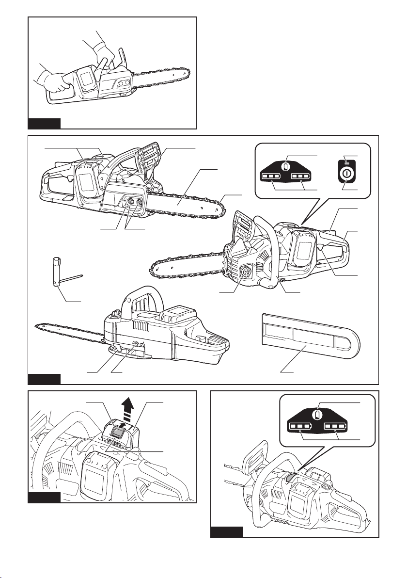
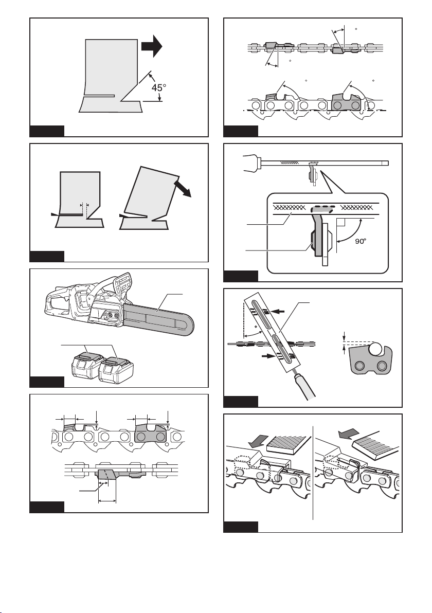
• Maintain a rm grip, with thumbs and
ngers encircling the chain saw handles,
with both hands on the saw and position
your body and arm to allow you to resist
kickback forces. Kickback forces can be
controlled by the operator, if proper precau-
tions are taken. Do not let go of the chain
saw.
►Fig.1
• Do not overreach and do not cut above
shoulder height. This helps prevent unin-
tended tip contact and enables better control
of the chain saw in unexpected situations.
• Only use replacement bars and chains
specied by the manufacturer. Incorrect
replacement bars and chains may cause
chain breakage and/or kickback.
• Follow the manufacturer’s sharpening
and maintenance instructions for the saw
chain. Decreasing the depth gauge height
can lead to increased kickback.
14. Before starting work, check that the chain
saw is in proper working order and that its
condition complies with the safety regulations.
Check in particular that:
• The chain brake is working properly;
• The run-down brake is working properly;
• Thebarandthesprocketcoveraretted
correctly;
• The chain has been sharpened and ten-
sioned in accordance with the regulations.
15. Do not start the chain saw with the chain cover
being installed on it. Starting the chain saw with
the chain cover being installed on it may cause
the chain cover to thrown out forward resulting in
personalinjuryanddamagetoobjectsaroundthe
operator.
16. Avoid dangerous environment. Don't use the
tool in damp or wet locations or expose it to
rain. Water entering the tool will increase the
risk of electric shock.
17. Do not dispose of the battery(ies) in a re. The
cell may explode. Check with local codes for
possible special disposal instructions.
18. Do not open or mutilate the battery(ies).
Released electrolyte is corrosive and may
cause damage to the eyes or skin. It may be
toxic if swallowed.
19. Do not charge battery in rain, or in wet
locations.
SAVE THESE INSTRUCTIONS.
WARNING: DO NOT let comfort or familiarity
with product (gained from repeated use) replace
strict adherence to safety rules for the subject
product. MISUSE or failure to follow the safety
rules stated in this instruction manual may cause
serious personal injury.
Important safety instructions for
battery cartridge
1. Before using battery cartridge, read all instruc-
tions and cautionary markings on (1) battery
charger, (2) battery, and (3) product using
battery.
2. Do not disassemble battery cartridge.
3. If operating time has become excessively
shorter, stop operating immediately. It may
result in a risk of overheating, possible burns
and even an explosion.

11 ENGLISH
4. If electrolyte gets into your eyes, rinse them
out with clear water and seek medical atten-
tion right away. It may result in loss of your
eyesight.
5. Do not short the battery cartridge:
(1) Do not touch the terminals with any con-
ductive material.
(2) Avoid storing battery cartridge in a con-
tainer with other metal objects such as
nails, coins, etc.
(3) Do not expose battery cartridge to water
or rain.
A battery short can cause a large current
ow, overheating, possible burns and even a
breakdown.
6. Do not store the tool and battery cartridge in
locations where the temperature may reach or
exceed 50 °C (122 °F).
7. Do not incinerate the battery cartridge even if
it is severely damaged or is completely worn
out. The battery cartridge can explode in a re.
8. Be careful not to drop or strike battery.
9. Do not use a damaged battery.
10. The contained lithium-ion batteries are subject
to the Dangerous Goods Legislation require-
ments.
For commercial transports e.g. by third parties,
forwarding agents, special requirement on pack-
aging and labeling must be observed.
For preparation of the item being shipped, consult-
ing an expert for hazardous material is required.
Please also observe possibly more detailed
national regulations.
Tape or mask off open contacts and pack up the
battery in such a manner that it cannot move
around in the packaging.
11. Follow your local regulations relating to dis-
posal of battery.
12. Use the batteries only with the products spec-
ied by Makita/Dolmar. Installing the batteries to
non-compliantproductsmayresultinare,exces-
sive heat, explosion, or leak of electrolyte.
SAVE THESE INSTRUCTIONS.
CAUTION: Only use genuine Makita/Dolmar
batteries. Use of non-genuine Makita/Dolmar batter-
ies, or batteries that have been altered, may result in
thebatteryburstingcausingres,personalinjuryand
damage. It will also void the Makita/Dolmar warranty
for the Makita/Dolmar tool and charger.
Tips for maintaining maximum
battery life
1. Charge the battery cartridge before completely
discharged. Always stop tool operation and
charge the battery cartridge when you notice
less tool power.
2. Never recharge a fully charged battery car-
tridge. Overcharging shortens the battery
service life.
3. Charge the battery cartridge with room tem-
perature at 10 °C - 40 °C (50 °F - 104 °F). Let
a hot battery cartridge cool down before
charging it.
4. Charge the battery cartridge if you do not use
it for a long period (more than six months).
PARTS DESCRIPTION
►Fig.2
1Battery cartridge 2Front hand guard 3Guide bar
4Saw chain 5Retaining nut 6Chainadjustingscrew
7Check button 8Capacity indicator 9Main power lamp
10 Main power switch 11 Lock-off lever 12 Rear handle
13 Switch trigger 14 Front handle 15 Oil tank cap
16 Box wrench 17 Chain catcher 18 Adjustingscrew(foroilpump)
19 Guide bar cover - - - -

12 ENGLISH
FUNCTIONAL DESCRIPTION
CAUTION: Always be sure that the tool is
switched off and the battery cartridge is removed
before adjusting or checking function on the tool.
Installing or removing battery cartridge
CAUTION: Always switch off the tool before
installing or removing of the battery cartridge.
CAUTION:
Hold the tool and the battery cartridge
rmly when installing or removing battery cartridge.
Failuretoholdthetoolandthebatterycartridgermlymay
cause them to slip off your hands and result in damage to
thetoolandbatterycartridgeandapersonalinjury.
►Fig.3: 1. Red indicator 2. Button 3. Battery cartridge
To remove the battery cartridge, slide it from the tool
while sliding the button on the front of the cartridge.
To install the battery cartridge, align the tongue on the battery car-
tridge with the groove in the housing and slip it into place. Insert it all
the way until it locks in place with a little click. If you can see the red
indicator on the upper side of the button, it is not locked completely.
CAUTION:
Always install the battery cartridge fully
until the red indicator cannot be seen. If not, it may accidentally
falloutofthetool,causinginjurytoyouorsomeonearoundyou.
CAUTION: Do not install the battery cartridge
forcibly. If the cartridge does not slide in easily, it is
not being inserted correctly.
NOTE:
The tool does not work with only one battery cartridge.
NOTE:
Payattentiontothepositionofyourngerswheninstall-
ing the battery. The button will be depressed unintentionally.
Tool / battery protection system
The tool is equipped with a tool/battery protection system. This
system automatically cuts off power to the motor to extend tool and
battery life. The tool will automatically stop during operation if the
tool or battery is placed under one of the following conditions.
Overload protection
When the tool is operated in a manner that causes it to
draw an abnormally high current, the tool automatically
stops and the main power lamp will blink. In this situation,
turn the tool off and stop the application that caused the
tool to become overloaded. Then turn the tool on to restart.
Overheat protection
When the tool is overheated, the tool automatically stops and
the capacity indicator lamp will blink as illustrated. In this situ-
ation, let the tool cool down before turning the tool on again.
Capacity indicator status Status
On Off Blinking
Overheated.
Overdischarge protection
When the battery capacity becomes low, the tool stops
automatically. If the product does not operate even
when the switches are operated, remove the batteries
from the tool and charge the batteries.
Indicating the remaining battery capacity
►Fig.4: 1. Check button 2. Capacity indicator
The remaining battery capacity is shown while you
are pressing the check button. The capacity indicators
correspond to each battery.
Capacity indicator status Remaining
battery
capacity
On Off Blinking
50% to 100%
20% to 50%
0% to 20%
Charge the
battery
Indicating the remaining battery
capacity
Only for battery cartridges with the indicator
►Fig.5: 1. Indicator lamps 2. Check button
Press the check button on the battery cartridge to indi-
cate the remaining battery capacity. The indicator lamps
light up for a few seconds.
Indicator lamps Remaining
capacity
Lighted Off Blinking
75% to 100%
50% to 75%
25% to 50%
0% to 25%
Charge the
battery.
The battery
may have
malfunctioned.
NOTE: Depending on the conditions of use and the
ambient temperature, the indication may differ slightly
from the actual capacity.

13 ENGLISH
Main power switch
WARNING: Always turn off the main power
switch when not in use.
To stand by the chain saw, press the main power switch
until the main power lamp lights up. To turn off, press
the main power switch again.
►Fig.6: 1. Main power switch
NOTE:
The main power lamp brinks if the switch trigger is
pulled under unoperatable conditions. The lamp blinks if you
• turn on the main power switch while holding
down the lock-off lever and the switch trigger;
•
pull the switch trigger while the chain brake is applied;
• release the chain brake while holding down the
lock-off lever and pulling the switch trigger.
NOTE: This chain saw employs the auto power-off
function. To avoid unintentional start up, the main
power switch will automatically shut down when the
switch trigger is not pulled for a certain period after
the main power switch is turned on.
Switch action
WARNING: For your safety, this tool is
equipped with lock-off lever which prevents the
tool from unintended starting. NEVER use the tool
if it runs when you simply pull the switch trigger
without pressing the lock-off lever. Return the
tool to our authorized service center for proper
repairs BEFORE further usage.
WARNING: NEVER tape down or defeat pur-
pose and function of lock-off lever.
CAUTION: Before installing the battery car-
tridge into the tool, always check to see that the
switch trigger actuates properly and returns to
the "OFF" position when released.
NOTICE: Do not pull the switch trigger hard with-
out pressing the lock-off lever. This can cause
switch breakage.
To prevent the switch trigger from being accidentally
pulled, a lock-off lever is provided. To start the tool,
depress the lock-off lever and pull the switch trigger.
Tool speed is increased by increasing pressure on the
switch trigger. Release the switch trigger to stop.
►Fig.7: 1. Switch trigger 2. Lock-off lever
Checking the chain brake
CAUTION: Hold the chain saw with both
hands when switching it on. Hold the rear handle
with your right hand, the front handle with your
left. The bar and the chain must not be in contact
with any object.
CAUTION: Should the saw chain not stop
immediately when this test is performed, the
saw may not be used under any circumstances.
Consult our authorized service center.
1. Press the lock-off lever, then pull the switch trig-
ger. The saw chain starts immediately.
2. Push the front hand guard forwards with the back
of your hand. Make sure that the chain saw comes to an
immediate standstill.
►Fig.8: 1. Front hand guard 2. Unlocked position
3. Locked position
Checking the run-down brake
CAUTION: If the saw chain does not stop
within one second in this test, stop using the
chain saw and consult our authorized service
center.
Run the chain saw then release the switch trigger com-
pletely. The saw chain must come to a standstill within
one second.
Adjusting the chain lubrication
Youcanadjusttheoilpumpfeedratewiththeadjusting
screw.Theamountofoilcanbeadjustedusingthe
universal wrench.
►Fig.9: 1.Adjustingscrew
ASSEMBLY
CAUTION: Always be sure that the tool is
switched off and the battery cartridge is removed
before carrying out any work on the tool.
CAUTION: Do not touch the saw chain with
bare hands. Always wear gloves when handling
the saw chain.
Removing or installing saw chain
CAUTION: The saw chain and the guide bar
are still hot just after the operation. Let them cool
down enough before carrying out any work on
the tool.
To remove the saw chain, perform the following steps:
1. Release the chain brake by pulling the front hand
guard.
2. Loosenthechainadjustingscrew,thentheretain-
ing nuts.
►Fig.10: 1.Chainadjustingscrew2. Retaining nut
3. Sprocket cover
3. Remove the sprocket cover then remove the saw
chain and guide bar from the chain saw body.
To install the saw chain, perform the following steps:
1. Make sure the direction of the chain. The arrow
mark on the chain shows the direction of the chain.
2. Fit in one end of the saw chain on the top of the
guide bar and the other end around the sprocket.
►Fig.11: 1. Sprocket
3. Rest the guide bar in place on the chain saw.

14 ENGLISH
4.
Place the sprocket cover on the chain saw so that the
adjustingpinispositionedinasmallholeontheguidebar.
►Fig.12: 1. Sprocket cover 2. Guide bar 3. Hole
4.Adjustingpin
5. Tighten the retaining nuts to secure the sprocket
cover,thenloosenitabitfortensionadjustment.
►Fig.13: 1. Retaining nut
Adjusting saw chain tension
CAUTION: Carry out the procedure of install-
ing or removing saw chain in a clean place free
from sawdust and the like.
CAUTION: Do not tighten the saw chain too
much. Excessively high tension of saw chain may
cause breakage of saw chain, wear of the guide bar
andbreakageoftheadjustingdial.
CAUTION: A chain which is too loose can
jump off the bar and it may cause an injury
accident.
The saw chain may become loose after many hours
of use. From time to time check the saw chain tension
before use.
1.
Release the chain brake by pulling the front hand guard.
2. Loosen the retaining nuts a bit to loosen the
sprocket cover lightly.
►Fig.14: 1. Retaining nut
3. Liftuptheguidebartipslightlyandadjustthe
chaintension.Turnthechainadjustingscrewclockwise
to tighten, turn it counterclockwise to loosen.
Tighten the saw chain until the lower side of the saw
chaintsintheguidebarrailasillustrated.
►Fig.15: 1. Guide bar 2. Saw chain 3.Chainadjust-
ing screw
4. Keep holding the guide bar lightly and tighten the
retaining nuts to secure the sprocket cover.
►Fig.16: 1. Retaining nut
Make sure that the saw chain does not loose at the
lowersideandthesawchaintssnuglyagainstthe
lower side of the bar.
OPERATION
Lubrication
Saw chain is automatically lubricated when the tool is in
operation. Check the amount of remaining oil in the oil
tank periodically.
Torellthetank,laythechainsawonitssideand
remove the oil tank cap. The proper amount of oil is 200
ml.Afterrellingthetank,makesurethattheoiltank
cap is tightened securely.
►Fig.17: 1. Oil tank cap 2. Oil tank (translucent)
Afterrelling,holdthechainsawawayfromthe
tree. Start it and wait until lubrication on saw chain is
adequate.
►Fig.18
NOTICE: When lling the chain oil for the rst
time, or relling the tank after it has been com-
pletely emptied, add oil up to the bottom edge of
the ller neck. The oil delivery may otherwise be
impaired.
NOTICE: Use the saw chain oil exclusively for
Makita/Dolmar chain saws or equivalent oil avail-
able in the market.
NOTICE: Never use oil including dust and parti-
cles or volatile oil.
NOTICE: When pruning trees, use botanical oil.
Mineral oil may harm trees.
NOTICE: Before the cutting operation, make sure
that the provided oil tank cap is screwed in place.
WORKING WITH THE CHAIN SAW
CAUTION: The rst time user should, as a
minimum practice, do cutting logs on a saw-horse
or cradle.
CAUTION: When sawing precut timber, use a
safe support (saw horse or cradle). Do not steady
the workpiece with your foot, and do not allow
anyone else to hold or steady it.
CAUTION: Secure round pieces against
rotation.
CAUTION: Keep all parts of the body away
from the saw chain when the motor is operating.
CAUTION: Hold the chain saw rmly with
both hands when the motor is running.
CAUTION: Do not overreach. Keep proper
footing and balance at all times.
NOTICE: Never toss or drop the tool.
NOTICE: Do not cover the vents of the tool.
Bring the bottom edge of the chain saw body into
contact with the branch to be cut before switching on.
Otherwise it may cause the guide bar to wobble, result-
ingininjurytooperator.Sawthewoodtobecutbyjust
moving it down by using the weight of the chain saw.
►Fig.19
If you cannot cut the timber right through with a single stroke:
Apply light pressure to the handle and continue sawing
and draw the chain saw back a little; then apply the spike
bumperalittlelowerandnishthecutbyraisingthehandle.
►Fig.20
Bucking
1. Rest the bottom edge of the chain saw body on
the wood to be cut.
►Fig.21
2. With the saw chain running, saw into the wood
while using the rear handle to raise the saw and the
front one to guide it. Use the spike bumper as a pivot.
3. Continue the cut by applying slight pressure to
the front handle, easing the saw back slightly. Move
the spike bumper further down the timber and raise the
front handle again.

15 ENGLISH
NOTICE: When making several cuts, switch the
chain saw off between cuts.
CAUTION: If the upper edge of the bar is used
for cutting, the chain saw may be deected in
your direction if the chain becomes trapped. For
this reason, cut with the lower edge, so that the
saw will be deected away from your body.
►Fig.22
When you cut a wood under tension, cut the pressured
side(A)rst.Thenmakethenalcutfromthetensioned
side (B). This prevents the bar from becoming trapped.
►Fig.23
Limbing
CAUTION: Limbing may only be performed by
trained persons. A hazard is presented by the risk
of kickback.
When limbing, support the chain saw on the trunk if
possible. Do not cut with the tip of the bar, as this pres-
ents a risk of kickback.
Pay particular attention to branches under tension. Do
not cut unsupported branches from below.
Do not stand on the felled trunk when limbing.
Burrowing and parallel-to-grain cuts
CAUTION:
Burrowing and parallel-to-grain cuts
may only be carried out by persons with special train-
ing.Thepossibilityofkickbackpresentsariskofinjury.
Perform parallel-to-grain cuts at as shallow an angle as
possible. Take an extra caution when carrying out the
cut as the spike bumper cannot be used.
►Fig.24
Felling
CAUTION: Felling work may only be per-
formed by trained persons. The work is hazardous.
Observe local regulations if you wish to fell a tree.
►Fig.25: 1. Felling area
— Before starting felling work, ensure that:
• Only persons involved in the felling operation
are in the vicinity;
•
Any person involved has an unhindered path
of retreat through a range of approximately
45° either side of the felling axis. Consider the
additional risk of tripping over electrical cables;
• The base of the trunk is free of foreign
objects,rootsandranches;
• Nopersonsorobjectsarepresentovera
distance of 2 1/2 tree lengths in the direction
in which the tree will fall.
— Consider the following with respect to each tree:
• Direction of lean;
• Loose or dry branches;
• Height of the tree;
• Natural overhang;
• Whether or not the tree is rotten.
— Consider the wind speed and direction. Do not
carry out felling work if the wind is gusting strongly.
—
Trimming of root swellings: Begin with the largest swell-
ings.Maketheverticalcutrst,thenthehorizontalcut.
— Stand to the side of the falling tree. Keep an area
clear to the rear of the falling tree up to an angle of
45° either side of the tree axis (refer to the “felling
area”gure).Payattentiontofallingbranches.
— An escape path should be planned and cleared
as necessary before cuts are started. The escape
path should extend back and diagonally to the rear
oftheexpectedlineoffallasillustratedingure.
►Fig.26: 1. Felling direction 2. Danger zone
3. Escape route
When felling trees, follow the procedures below:
1.
Cut a scarf as close to the ground as possible. First make
the horizontal cut to a depth of 1/5 -1/3 of the trunk diameter. Do
not make the scarf too large. Then make the diagonal cut.
►Fig.27
NOTE: The scarf determines the direction in which
the tree will fall, and guides it. It is made on the side
towards which the tree is to fall.
2.
Make the back cut a little higher than the base cut of
the scarf. The back cut must be exactly horizontal. Leave
approximately 1/10 of the trunk diameter between the back
cutandthescarf.Thewoodbersintheuncuttrunkpor-
tion act as a hinge. Insert wedges into the back cut in time.
►Fig.28
WARNING: Do not cut right through the bers
under any circumstances. The tree will otherwise
fall unchecked.
NOTICE: Only plastic or aluminum wedges may
be used to keep the back cut open. The use of
iron wedges is prohibited.
Carrying tool
Before carrying the tool, always apply the chain brake and
remove the battery cartridges from the tool. Then attach the guide
bar cover. Also cover the battery cartridge with the battery cover.
►Fig.29: 1. Guide bar cover 2. Battery cover
MAINTENANCE
CAUTION:
Always be sure that the tool is
switched off and the battery cartridge is removed before
attempting to perform inspection or maintenance.
CAUTION: Always wear gloves when perform-
ing any inspection or maintenance.
NOTICE: Never use gasoline, benzine, thinner,
alcohol or the like. Discoloration, deformation or
cracks may result.
To maintain product SAFETY and RELIABILITY, repairs,
anyothermaintenanceoradjustmentshouldbeper-
formed by Makita/Dolmar Authorized or Factory Service
Centers, always using Makita/Dolmar replacement parts.

16 ENGLISH
Sharpening the saw chain
Sharpen the saw chain when:
• Mealy sawdust is produced when damp wood is
cut;
• Thechainpenetratesthewoodwithdifculty,even
when heavy pressure is applied;
• The cutting edge is obviously damaged;
• The saw pulls to the left or right in the wood.
(caused by uneven sharpening of the saw chain or
damage to one side only)
Sharpen the saw chain frequently but a little each time.
Twoorthreestrokeswithaleareusuallysufcientfor
routine resharpening. When the saw chain has been
resharpened several times, have it sharpened in our
authorized service center.
Sharpening criteria:
WARNING: An excessive distance between
the cutting edge and depth gauge increases the
risk of kickback.
►Fig.30: 1. Cutter length 2. Distance between cutting
edge and depth gauge 3. Minimum cutter
length (3 mm)
— All cutter length must be equal. Different cutter
lengths prevent the saw chain from running
smoothly and may cause the saw chain to break.
— Do not sharpen the chain when the cutter length
has reached 3 mm or shorter. The chain must be
replaced with new one.
— The chip thickness is determined by the distance
between the depth gauge (round nose) and the
cutting edge.
— The best cutting results are obtained with following
distance between cutting edge and depth gauge.
• Chainblade90PX:0.65mm(0.025″)
• Chainblade91PX:0.65mm(0.025″)
►Fig.31
— The sharpening angle of 30° must be the same on
all cutters. Different cutter angles cause the chain
to run roughly and unevenly, accelerate wear, and
lead to chain breaks.
— Useasuitableroundlesothatthepropersharp-
ening angle is kept against the teeth.
• Chain blade 90PX : 55°
• Chain blade 91PX : 55°
File and le guiding
— Useaspecialroundle(optionalaccessory)for
saw chains to sharpen the chain. Normal round
lesarenotsuitable.
— Diameteroftheroundleforeachsawchainisas
follows:
• Chainblade90PX:4.5mm(3/16″)
• Chainblade91PX:4.0mm(5/32″)
— Theleshouldonlyengagethecutteronthefor-
wardstroke.Lifttheleoffthecutteronthereturn
stroke.
— Sharpentheshortestcutterrst.Thenthelength
of this shortest cutter becomes the standard for all
other cutters on the saw chain.
— Guidetheleasshowninthegure.
►Fig.32: 1. File 2. Saw chain
—
Thelecanbeguidedmoreeasilyifaleholder
(optionalaccessory)isemployed.Theleholderhas
markings for the correct sharpening angle of 30° (align
the markings parallel to the saw chain) and limits the
depthofpenetration(to4/5ofthelediameter).
►Fig.33: 1. File holder
— After sharpening the chain, check the height of the
depth gauge using the chain gauge tool (optional
accessory).
►Fig.34
— Removeanyprojectingmaterial,howeversmall,
withaspecialatle(optionalaccessory).
— Round off the front of the depth gauge again.
Cleaning the guide bar
Chips and sawdust will build up in the guide bar groove.
Theymayclogthebargrooveandimpairtheoilow.
Clean out the chips and sawdust every time when you
sharpen or replace the saw chain.
►Fig.35
Cleaning the sprocket cover
Chips and saw dust will accumulate inside of the
sprocket cover. Remove the sprocket cover and saw
chain from the tool then clean the chips and saw dust.
►Fig.36
Cleaning the oil discharge hole
Small dust or particles may be built up in the oil dis-
charge hole during operation. These dust or particles
mayimpairtheoiltoowandcauseaninsufcient
lubrication on the whole saw chain. When a poor chain
oil delivery occurs at the top of guide bar, clean the oil
discharge hole as follows.
1.
Remove the sprocket cover and saw chain from the tool.
2. Remove the small dust or particles using a slotted
screwdriver with a slender shaft or the like.
►Fig.37: 1. Slotted screwdriver 2. Oil discharge hole
3. Insert the battery cartridge into the tool. Pull the
switchtriggertoowbuilt-updustorparticlesofftheoil
discharge hole by discharging chain oil.
4. Remove the battery cartridge from the tool.
Reinstall the sprocket cover and saw chain on the tool.
Replacing the sprocket
CAUTION:
A worn sprocket will damage a new
saw chain. Have the sprocket replaced in this case.
Beforettinganewsawchain,checktheconditionof
the sprocket.
►Fig.38: 1. Sprocket 2. Areas to be worn out
Alwaystanewlockingringwhenreplacingthe
sprocket.
►Fig.39: 1. Locking ring 2. Sprocket
NOTICE: Make sure that the sprocket is installed
as shown in the gure.

17 ENGLISH
Storing the tool
1. Clean the tool before storing. Remove any chips
and sawdust from the tool after removing the sprocket
cover.
2. After cleaning the tool, run it under no load to lubri-
cate the saw chain and guide bar.
3. Cover the guide bar with the guide bar cover.
4. Empty the oil tank.
Instructions for periodic maintenance
To ensure long life, prevent damage and ensure the full functioning of the safety features, the following maintenance
must be performed regularly. Warranty claims can be recognized only if this work is performed regularly and prop-
erly. Failure to perform the prescribed maintenance work can lead to accidents! The user of the chain saw must not
perform maintenance work which is not described in the instruction manual. All such work must be carried out by our
authorized service center.
Check item / Operating time Before
operation Everyday Every week Every 3
month Annually Before
storage
Chain saw Inspection. -----
Cleaning. -----
Check at
authorized
service center.
----
Saw chain Inspection. -----
Sharpening if
necessary.
-----
Guide bar Inspection. ----
Remove from
the chain saw.
-----
Chain brake Check the
function.
-----
Have it
inspected
regularly at
authorized
service center.
--- - -
Chain
lubrication
Check the oil
feed rate.
-----
Switch trigger Inspection. -----
Lock-off lever Inspection. -----
Oil tank cap Check
tightness.
-----
Chain catcher Inspection. - - ---
Screws and
nuts
Inspection. - - ---

18 ENGLISH
TROUBLESHOOTING
Beforeaskingforrepairs,conductyourowninspectionrst.Ifyoundaproblemthatisnotexplainedinthemanual,
do not attempt to dismantle the tool. Instead, ask Makita/Dolmar Authorized Service Centers, always using Makita/
Dolmar replacement parts for repairs.
Malfunction status Cause Action
The chain saw does not start. Two battery cartridges are not installed. Install two charged battery cartridges.
Battery problem (low voltage). Recharge the battery cartridges. If recharg-
ing is not effective, replace the battery
cartridge.
Main power switch is off. The chain saw is automatically turned off if
it is un-operated for a certain period. Turn
on the main power switch again.
The saw chain does not run. Chain brake activated. Release chain brake.
The motor stops running after a little use. Battery's charge level is low. Recharge the battery cartridges. If recharg-
ing is not effective, replace the battery
cartridge.
No oil on the chain. Oil tank is empty. Fill the oil tank.
Oil guide groove is dirty. Clean the groove.
Poor oil delivery. Adjusttheamountofoildeliverywiththe
adjustingscrew.
The chain saw does not reach maximum
RPM.
Battery cartridge is installed improperly. Install the battery cartridges as described
in this manual.
Battery power is dropping. Recharge the battery cartridges. If recharg-
ing is not effective, replace the battery
cartridge.
The drive system does not work correctly. Ask the authorized service center in your
region for repair.
The main power lamp is blinking. Switch trigger is pulled under an unoperat-
able condition.
Pull the switch trigger after the main power
switch is turned on and the chain brake is
released.
Chain does not stop even the chain brake
is activated:
Stop the machine immediately!
The brake band is worn down. Ask the authorized service center in your
region for repair.
Abnormal vibration:
Stop the machine immediately!
Loose guide bar or saw chain. Adjusttheguidebarandsawchain
tension.
Tool malfunction. Ask the authorized service center in your
region for repair.
OPTIONAL
ACCESSORIES
CAUTION: These accessories or attachments
are recommended for use with your Makita/
Dolmar tool specied in this manual. The use of
any other accessories or attachments might present
ariskofinjurytopersons.Onlyuseaccessoryor
attachment for its stated purpose.
If you need any assistance for more details regard-
ing these accessories, ask your local Makita/Dolmar
Service Center.
• Saw chain
• Guide bar
• Guide bar cover
• File
• Tool bag
• Makita/Dolmar genuine battery and charger
WARNING: If you purchase a guide bar of
different length from the standard guide bar, also
purchase a suitable guide bar cover together. It
must t and fully cover the guide bar on the chain
saw.
NOTE: Some items in the list may be included in the
tool package as standard accessories. They may
differ from country to country.

19 POLSKI
POLSKI (Instrukcja oryginalna)
DANE TECHNICZNE
Model: AS3935
Całkowitadługość(bezprowadnicy) 443 mm
Napięcieznamionowe Prądstały36V
Masa netto 4,7–5,4 kg
Standardowadługośćprowadnicy 350 mm
Zalecanadługośćprowadnicy 300 - 400 mm
Odpowiednitypłańcuchatnącego
(patrzwtabeliponiżej)
90PX
91PX
Kołołańcuchowe Liczbazębów 6
Podziałka 3/8″
Prędkośćłańcucha 0 – 20 m/s
(0 – 1 200 m/min)
Pojemnośćzbiornikaolejułańcuchowego 200 cm3
• Wzwiązkuzestaleprowadzonymprzeznasząrmęprogramembadawczo-rozwojowymniniejszedanemogą
uleczmianombezwcześniejszegopowiadomienia.
• Danetechnicznemogąróżnićsięwzależnościodkraju.
• Masamożebyćróżnawzależnościodosprzętu,wtymakumulatora.Wtabeliprzedstawionajestnajlżejszai
najcięższakonguracja,zgodniezprocedurąEPTA01/2014.
Kompatybilne akumulatory
BL1815N / BL1820 / BL1820B / BL1830 / BL1830B / BL1840 / BL1840B / BL1850 / BL1850B / BL1860B / AP-183
• Pewnezwymienionychpowyżejakumulatorówmogąbyćniedostępnewregioniezamieszkaniaużytkownika.
OSTRZEŻENIE: Należy używać wyłącznie akumulatorów wymienionych powyżej.Używanieinnychaku-
mulatorówmożestwarzaćryzykowystąpieniaobrażeńciałalubpożaru.
Łańcuch tnący i prowadnica
Typ łańcucha tnącego 90PX
Liczbaogniwnapędowych 46 52 56
Prowadnica Długośćprowadnicy 300 mm 350 mm 400 mm
Długośćcięcia 275 mm 330 mm 370 mm
Podziałka 3/8″
Wskaźnik 1,1 mm
Typ Prowadnica gwiazdkowa
Typ łańcucha tnącego 91PX
Liczbaogniwnapędowych 46 52 56
Prowadnica Długośćprowadnicy 300 mm 350 mm 400 mm
Długośćcięcia 275 mm 330 mm 370 mm
Podziałka 3/8″
Wskaźnik 1,3 mm
Typ Prowadnica gwiazdkowa
OSTRZEŻENIE:Należyużywaćprowadnicyiłańcuchatnącego,któredosiebiepasują.Wprzeciwnymrazie
możetoprzyczynićsiędopowstaniaobrażeń.

20 POLSKI
Symbole
Poniżejpokazanosymbolezastosowanenaurządze-
niu.Przedrozpoczęciemużytkowanianależyzapoznać
sięzichznaczeniem.
Przeczytaćinstrukcjęobsługi.
Nosićokularyochronne.
Nosićochronnikisłuchu.
Nosićkask,gogleorazochronnikisłuchu.
Stosowaćodpowiednieśrodkiochronystóp
inógorazdłoniiramion.
Chronićprzedwilgocią.
Maksymalnadopuszczalnadługośćcięcia
Kierunekposuwułańcucha
Regulacjasmarowaniapilarkiłańcuchowej
Ni-MH
Li-ion
DotyczytylkopaństwUE
Niewyrzucaćurządzeńelektrycznychani
akumulatorówwrazzodpadamizgospo-
darstwa domowego!
Zgodniezdyrektywamieuropejskimiwspra-
wiezużytegosprzętuelektrycznegoielek-
tronicznegoorazbateriiiakumulatoróworaz
zużytychbateriiiakumulatorów,atakżedosto-
sowaniemichdoprawakrajowego,zużyte
urządzeniaelektryczne,baterieiakumulatory,
należyskładowaćosobnoiprzekazywaćdo
zakładurecyklingudziałającegozgodniez
przepisamidotyczącymiochronyśrodowiska.
Przeznaczenie
Pilarkałańcuchowajestprzeznaczonadocięciadrewna.
Hałas
TypowyrównoważnypoziomdźwiękuAokreślonyw
oparciuonormęEN60745-2-13:
Poziomciśnieniaakustycznego(LpA): 87,7 dB(A)
Poziommocyakustycznej(LWA): 100,4 dB (A)
Niepewność(K):2dB(A)
OSTRZEŻENIE: Nosić ochronniki słuchu.
Drgania
Całkowitawartośćpoziomudrgań(sumawektoróww3
osiach)określonazgodnieznormąEN60745-2-13:
Trybpracy:Cięciedrewna
Emisjadrgań(ah,W): 5,3 m/s2
Niepewność(K):1,5m/s2
WSKAZÓWKA:Deklarowanawartośćwytwarzanych
drgańzostałazmierzonazgodniezestandardową
metodątestowąimożnająwykorzystaćdoporówny-
wanianarzędzi.
WSKAZÓWKA:Deklarowanąwartośćwytwarzanych
drgańmożnatakżewykorzystaćwewstępnejocenie
narażenia.
OSTRZEŻENIE: Drgania wytwarzane podczas
rzeczywistegoużytkowaniaelektronarzędziamogą
sięróżnićodwartoścideklarowanej,wzależnościod
sposobujegoużytkowania.
OSTRZEŻENIE: W oparciu o szacowane
narażeniewrzeczywistychwarunkachużytkowania
należyokreślićśrodkibezpieczeństwawceluochrony
operatora(uwzględniającwszystkieelementycyklu
działania,tj.czas,kiedynarzędziejestwyłączonei
kiedypracujenabiegujałowym,atakżeczas,kiedy
jestwłączone).
Deklaracja zgodności WE
Dotyczy tylko krajów europejskich
DeklaracjazgodnościWEjestdołączonajakozałącznik
Adoniniejszejinstrukcjiobsługi.
OSTRZEŻENIA DOTYCZĄCE
BEZPIECZEŃSTWA
Ogólne zasady bezpiecznej
eksploatacji elektronarzędzi
OSTRZEŻENIE: Należy zapoznać się z
ostrzeżeniami dotyczącymi bezpieczeństwa,
instrukcjami, ilustracjami i danymi technicz-
nymi dołączonymi do tego elektronarzędzia.
Niezastosowaniesiędopodanychponiżejinstrukcji
możeprowadzićdoporażeniaprądem,pożarui/lub
poważnychobrażeńciała.
Wszystkie ostrzeżenia i instruk-
cje należy zachować do wykorzy-
stania w przyszłości.
Pojęcie„elektronarzędzie",występującewwymienio-
nychtuostrzeżeniach,odnosisiędoelektronarzędzia
zasilanegozsiecielektrycznej(zprzewodemzasilają-
cym)lubdoelektronarzędziaakumulatorowego(bez
przewoduzasilającego).
Ostrzeżenia dotyczące bezpieczeństwa
dla akumulatorowej pilarki łańcuchowej
1. Przy włączonej pilarce łańcuchowej należy
trzymać wszystkie części ciała z dala od łań-
cucha tnącego. Przed rozpoczęciem pracy
z pilarką łańcuchową należy upewnić się, że
łańcuch tnący niczego nie dotyka. Chwila nie-
uwagipodczaspracypilarkimożespowodować
pochwycenieczęściubranialubciała.
Other manuals for AS3935
1
Table of contents
Languages:
Other Dolmar Chainsaw manuals

Dolmar
Dolmar PS-34 Instruction Manual

Dolmar
Dolmar PS-4605 User manual

Dolmar
Dolmar ES-183 A Guide

Dolmar
Dolmar PS-352 User guide

Dolmar
Dolmar ES-154 User manual

Dolmar
Dolmar PS-33 Guide

Dolmar
Dolmar PS-352 User guide

Dolmar
Dolmar AS-1212LG User manual

Dolmar
Dolmar AS-3625 User manual

Dolmar
Dolmar PS-3410 TH TLC Guide

Dolmar
Dolmar ES-164 TLC User manual

Dolmar
Dolmar ES-34 TLC User manual

Dolmar
Dolmar AS1925Z User manual

Dolmar
Dolmar AS3835 User manual

Dolmar
Dolmar 109 HappyStart User manual

Dolmar
Dolmar AS-1212LG User manual

Dolmar
Dolmar PS-3410 TH TLC Instruction Manual

Dolmar
Dolmar PS-510 Instruction Manual

Dolmar
Dolmar PS-3410 TLC Guide

Dolmar
Dolmar PS-9010 Instruction Manual