Dolphin DAS400 User manual

1
Protecting Your Pride
OWNERS
MANUAL

2
CONTENTS
Contents 2
Introduction 3
GeneralInstallationGuide 4
InstallationofDAS400/450/470
DPS400/450/455/470
DMS400/450/455/470 5
InstallationofDPS400F/450F
DMS400F/450F 6
InstallationofDMS600/650/655 7
InstallationofDMS600F/650F 8
InstallationofDPPK1/2/3/4 9
InstallationofDPS400D&DPS400M 10
Troubleshooting 11
SpareParts&Accessories 13
TechnicalSpecication 14
Warranty 15
Important – Please Read
DolphinParkingSensorsTMisatrademarkofTradingDirectLtd
Pleasenotetheseproductsaredesignedasanaidtohelpyouinyourreversingandparking
manoeuvresandarenotasubstituteforusingyourmirrors.Pleasedrivewithinthelimitationsof
theroadconditionsandyourabilityatalltimes.TradingDirectLtdassumesnoresponsibilityfor
anydamageorinjuryhowsoeverarisingfromtheuseofthisproduct.

3
ThankyouforchoosingourDolphin
ParkingSensorsTMWehopethis
manualhelpsyousuccessfully
installtheseawardwinningparking
sensorssotheyprovidemany
yearsofassistanceinyourparking
manoeuvres.
ParkingSensorsdetectobstaclesto
aidyourparkingandenableyouto
getintothosetightspotswithout
damagingyourcar.UsingUltrasonic
technologytheyemitaconeofsound
behindyourcar,whichbouncesoff
theobstructionandreturnstothe
sensor.Thetimetakenforthese
soundwavestobounceoffandreturn
fromobstructionsbehindyourcaris
howtheycalculatethedistanceto
theobstaclebehindyou.Sometimes
referredtoasradarorsonar,thisis
thesameprincipleusedfornavigation
byDolphinsatsea.
Thismanualcoversarangeofdifferent
DolphinParkingSensorTMkitsso
pleaserefertothesectionrelevantto
thesystemyouhavepurchased.Inan
efforttoprovideourcustomerswith
thebestpossibleproductourrange
isalwaysunderacycleofcontinuous
improvementanddevelopmentand
thereforeproductspecicationis
subjecttochangewithoutnotice.
Thereforesometimestheseinstructions
maynotcorrelate100%totheproduct
youhavepurchased,forwhichwe
apologise.
INTRODUCTION

4
TheDolphinParkingSensorsaredesigned
for12vvehicleswithpolycarbonatebumpers.
Resultscannotbeguaranteedwhenttingto
metalbumpersandwillnotworkwhentted
tobullbarsorotherenclosedsteelframes.
Inthisinstancewesuggestusingbracketsfor
mountingunderthebumper,whichcanbe
supplieddirectbyusifrequired.
Thesensorsshouldbeinstalledbetween
40-70cmoffthegroundandbetween30-
40cmapart.Wherepossibletheyshouldbe
ttedlevelandevenlyacrossthebumperfor
bestresultsandoverallappearancebutthe
sensorswillstillworkifthisisnotpossible.
Ifindoubtoryouhaveapotentialissue
withatow-barorrearmountedsparewheel
weadvisepoweringupthesensorsoff
thereversinglightfeedorsuitablebattery
power(a9vsquarePP3typewillsufce
topowerindividualsensors)andholding
asensorwhereyouareplanningtomount
it,toseethatitsnotdetectingtheobstacle
inquestionbeforedrillingthebumper.This
isalsoadvisableifyouaremountingthem
ratherloworifthebumperisangleddown
tothegroundwhereyouplantoinstallthem.
Beforedrillingthebumper,checkthatthereis
clearancebehindtohousethesensors,which
willrequireapprox25mmofdepthbefore
youreachanysteelbarsorxingbrackets.
Itisnotalwaysnecessarytoremovethe
bumpercoveringtodrillthesensors,butyou
mayndthiseasierinthelongrun.Ifyou
areunsurewheretotthesensorsplease
checkwithyourlocalcardealershiporhave
alookontheirforecourttoseewherethe
sensorshavebeenttedonsimilarmodels.
Onceyouhavedecidedonthelocationfor
yoursensorswewouldrecommendapplying
somemaskingtapeorsimilaradhesiveon
whichtoetchtheexactlocationforthedrill
bitanddoublecheckyourmeasurements.
Thistapewillthenalsoholdthedrillbitand
remainingpaintworkinplace.Thecorrect
drillbitwillbesuppliedwiththeDolphin
ParkingSensorTMkitsuppliedwhichinmost
instanceswillbe21mmindiameter.When
drillingdonotpushhardandforcethedrill
bit,leaveittodothehardwork.
Whenyouhavedrilledtheholespassthe
sensorcablingthroughandpushthesensors
intoplace.Youmayndtwosmallholes
ordotsonthebackofthesensors,and
thesensorshouldbettedwiththesedots
alignedvertically.Foampaddingislocated
onthesidesofthesensorsandthiswill
adequatelyholdthesensorsinplaceonce
tted.
Generally,onthelefthandsideoftheboot
undertheinteriorcarpetlining,youwill
ndagrommetwithvariouscablespassing
throughintothebootcompartment.You
shouldroutetheparkingsensorstoutilise
thisgrommetandfeedthesensorcabling
intothebootcompartment.Otherwise
asmallholecanbedrilledintotheside
foot-wellofthebootandsecuredusinga
rubbergrommetorsiliconsealant.Secure
anyexcesscablingunderthebumperwith
suitableretainersrunningsparecableback
andforthinstraightlines.
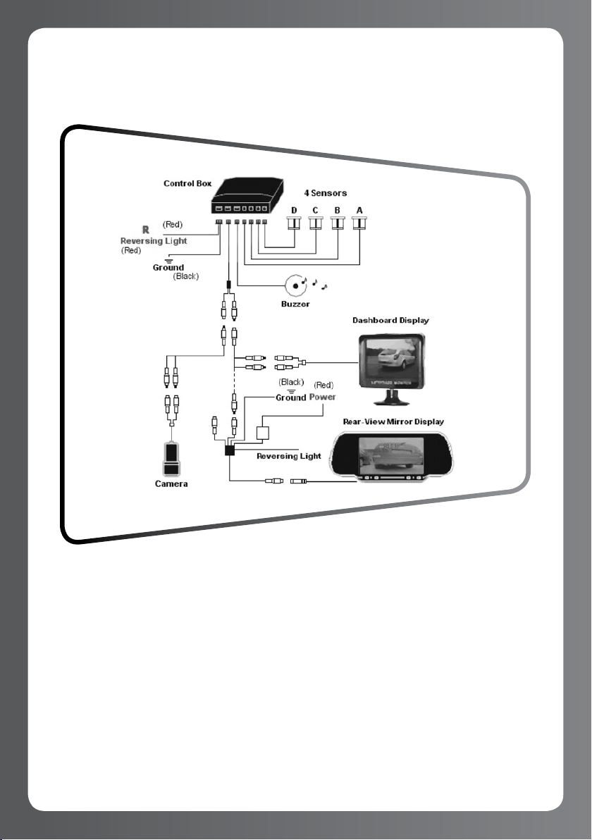
Topowerthesystemyouwillneedtogain
accesstothebackofthelightclusterto
identifythecablesrequired.Pleasesee
theinstallationdiagramsinthemanual
whichrefertoyourparticularmodelfor
theconnectionsrequired.Allconnections
shouldbemadetothecablesascloseto
therearlightclusterasreasonablypossible.
Thecircuitryofwirescanbetestedwitha
voltmeterorbyskinningabitofinsulation
offacabletocheckitcarriesthecorrect
voltagewhenrequired.Cablescantheneither
betwistedontothisbarewireorconnected
usingasuitablescotchlockconnecter.
MostmoderncarshaveMultiplexedor
CANBUSwiringsystems.DolphinParking
SensorsTMcanbettedonsuchcarsasyou
arejustconnectinginmostcasesfora12v+
feedandGround.Multiplexedwirescarry
codedinformationsignalsandshouldnotbe
touched.Inallcaseswewouldadviseagainst
cuttinganyoriginalwiresonthevehicle.
GENERAL INSTALLATION GUIDE

5
INSTALLATION FOR 4 SENSORS
DAS400/450/470 DPS400/450/455/470
DMS400/450/455/470
Thisdiagramisfortting4sensorsat
therearofthecarwiththebuzzeror
displayoption.
Forthe400audioonlybuzzermodels,
thisispluggedintothesocketmarked
DISP.Thisisaloudbuzzerandon
mostcars,certainlyhatchbacksand
estates,thiscanbemountedintheboot
compartmentandeasilybeheardatthe
frontofthecar.
Ifyouhavethe450ora455display
systemthebuzzerisbuiltintotheback
ofthedisplayandisnotaseparate
item.Thedisplayisona6mcable,the
450displayisdesignedtobemounted
onthedashboard.The455displayis
bothinvertedandreectedsoitcanbe
readbackwardsthroughyourreversing
mirrorandisdesignedtobemountedto
theroofintherearofthevehicle.
The470Wirelessdisplayalso
incorporatesabuzzer.Thiscomes
withacigarlighterplugontheend
forquickandeasyinstallation.Ifyou
wishthisplugcanbecutoffandthe
lead‘hardwired’tothefuseboxoran
appropriateignitionswitchedpower
feed.Thedisplaywillthenalwaysbelive
readytoreceiveasignalbutwillonly
comeonwhenreversegearisselected
andasignalisreceivedfromthebrain
boxintheboot.Weonlyrecommend
hardwiringthedisplayoncetherestof
thekitisfullyinstalledandtestedas
working.

6
The400F/450Fissuppliedwithlonger
6msensorstotaroundtheengine
bay.Thesensorcablingshouldberun
downtheoppositesideoftheengine
baytowherethebatteryissituatedto
avoidelectricalinterference.TheBrain
boxshouldbemountedunderneath
thedashboardbutawayfromthefuse
boxandanythingelselikelytocause
electricalinterference.
Arockerswitchissuppliedforyou
tomanuallyturnthefrontsensors
onasandwhenyouneedthem.This
shouldbeconnectedtoanignition
switchedfeed,thatisapowersource
thatislivewhenthecarison,such
asthecarstereosystem.Alternatively
youmayliketovisityourlocalcar
dealerships’partsdepartmenttogeta
blankswitchthatmatchesthedesign
oftheothersonyourdashboard.
Optionallyifyouhaveamodern
CANBuswiredcaryoumayhave
additionallypurchased(orcan
purchase,seeSpares&Accessories)
aCANBusinterfacethatwilltakea
speedreadingforthecarsengine
managementsystemandautomatically
bringthesensorsonwheneveryour
speedisbelowapproximately6mph.
INSTALLATION OF FRONT SENSOR ONLY KIT
DPS400F/450F DMS400F/450F

7
Thisdiagramisfortting6Micro
sensorsattherearofthecarwith
eitherabuzzer(DMS600),dashboard
display(DMS650)orrearroofdisplay
(DMS655).
TheMicrosensorshaveaslightangle
mouldedintothemandshouldbe
ttedtofaceslightlyup.Theouter
sensorsAandFarelesssensitive
andaredesignedtobemountedon
thesidesofthebumpertocoverthe
coverswiththemiddlesensorsB–E
coveringtherear.
Forthe600audioonlybuzzermodels,
thisispluggedintothesocketmarked
DISP.Thisisaloudbuzzerandon
mostcars,certainlyhatchbacksand
estates,thiscanbemountedinthe
bootcompartmentandeasilybeheard
atthefrontofthecar.
Ifyouhavethe650ora655display
systemthebuzzerisbuiltintothe
backofthedisplayandisnota
separateitem.Thedisplayisona6m
cable,the650displayisdesigned
tobemountedonthedashboard.
The655displayisbothinvertedand
reectedsoitcanbereadbackwards
throughyourreversingmirrorandis
designedtobemountedtotheroofin
therearofthevehicle.SensorsA,B,C
arerelativetoonesideofthedisplay
andD,E,Ftheothersidetoindicate
whichsideisclosesttoanobjectwith
adigitalcountdownin10cmunitsin
themiddleofthedisplay.
INSTALLATION OF 6 SENSOR REAR KIT
DMS 600/650/655

8
Thisdiagramisfortting6Micro
sensorsatthefrontofthecarwith
eitherabuzzer,600F,ordashboard
display,650F.
TheMicrosensorshaveaslightangle
mouldedintothemandshouldbetted
tofaceslightlyup.Theoutersensors
AandFarelesssensitiveandare
designedtobemountedonthesidesof
thebumpertocoverthecoverswiththe
middlesensorsB–Ecoveringtherear.
The600F/650Fissuppliedwithlonger
6msensorstotaroundtheengine
bay.Thesensorcablingshouldberun
downtheoppositesideoftheengine
baytowherethebatteryissituatedto
avoidelectricalinterference.TheBrain
boxshouldbemountedunderneath
thedashboardbutawayfromthefuse
boxandanythingelselikelytocause
electricalinterference.
Arockerswitchissuppliedforyouto
manuallyturnthefrontsensorsonas
andwhenyouneedthem.Thisshould
beconnectedtoanignitionswitched
feed,thatisapowersourcethatislive
whenthecarison,suchasthecar
stereosystem.Alternativelyyoumaylike
tovisityourlocalcardealerships’parts
departmenttogetablankswitchthat
matchesthedesignoftheotherson
yourdashboard.
OptionallyifyouhaveamodernCANBus
wiredcaryoumayhaveadditionally
purchased(orcanpurchase,seeSpares
&Accessories)aCANBusinterface
thatwilltakeaspeedreadingfor
thecarsenginemanagementsystem
andautomaticallybringthesensors
onwheneveryourspeedisbelow
approximately6mph.
INSTALLATION OF 6 SENSOR FRONT KIT DMS 600F/650F

9
DPPK1
Rear:DPS400
Front:DPS400F
DPPK2
Rear:DPS450
FrontDPS400F
DPPK3
Rear:DPS455
FrontDPS400F
DPPK4
Rear:DPS455
FrontDPS450F
INSTALLATION OF DPPK1/2/3/4
Thesekitsarecombinationpackagestogiveyouarangeofoptionsforfrontandrearsensors.
Fortheinstallationofthesepackagespleaseseethepageswhicharerelevanttothekitsthat
makeupyourDPPKsystemasfollows.
IfyouhavealsopurchasedarelayorCANBusmoduleforthefrontsensorspleaserefertothe
separateinstructionssuppliedwiththepartsfortheirinstallation.

10
TheabovediagramshowstheDPS400M
rear-viewmirrordisplayoptionbut
thisisalsoavailablewithadashboard
mounteddisplayoption,DPS400D.
Adigitaldistanceread-outthesame
asshownofthedisplaymodels
DPS450/650/850isalsooverlaidontop
ofthepictureofwhatisbehindyou.
Themonitorneedstobepoweredfrom
theinteriorlightfeedorotherpower
sourcefromthefrontofthecarandcan
beconnectedtoareversinglightfeedto
trigger.TheDashboardMonitorcanbe
poweredfromthewiringofthecontrol
boxoritcanbepoweredindependently.
Thebuzzerisseparateonthissystem
andcanbemountedintherearofthe
vehicle.Thisisaloudbuzzerandon
mostcars,certainlyhatchbacksand
estates,thiscanbemountedintheboot
compartmentandeasilybeheardatthe
frontofthecar.
Pleasenotethecameraisadifferent
sizetothesensorsandseparatedrill
pieceissuppliedforthecamera.Make
sureyoudrilltheholesforthesensors
withthecorrectsizeddrillpiece.
INSTALLATION OF SYSTEM WITH REVERSING CAMERA &
MONITOR DPS400M / DPS400D

11
FAULT – Detection range is not as expected
Somesurfacesaremoreabsorbentandlessreectivethanothersandyouwillgeta
bettersignaloffcarsandwallsthanbushesandrailingswherethedetectionrange
mayjustkickinatacloserdistance.Iftestingthesensorsbywalkingtowardsthem
yourclotheswillabsorbsomesoundwavesandbetterresultscanbeachievedby
holdingacoupleoflargebooksorfoldersundereacharmface-ontothesensors.
TROUBLESHOOTING
FAULT – Constant tone alerts when
parking sensors are activated.
Thiscouldbeduetooneofthesensors
havingdevelopedandfaultorkinkin
thecablecausingashortcircuitofthe
signal.Totestthisactivatethesensors
sothefaultispresentandthenunplug
eachsensoroneatatimefromthe
brainbox.Ifthefaultdisappearswith
oneofthesensorsunpluggedthenthe
sensorisfaulty,pleasecontactusfora
replacement.
FAULT – Unit appears dead.
Checkthepowersourceissendinga
livefeed.Checkandtryanalternative
sourcefortheground/earthconnection.
IftheseappearOKthenitcouldsimply
beafaultybuzzerorpossiblythebrain
box,ifwhichcasecontactusfora
replacement.
FAULT – Rear sensors work OK but
no signal from front sensors (or vice
versa).
Checkbrainboxiswiredcorrectlyas
follows.Red:Ignition,Black:Ground,
Yellow:ReversingLight,Blue:Brake
Light.Checkthattheparkingsensor
cablesdonotrunclosetothecar
batterywhichgeneratesanelectrical
eldwhichcouldbe‘drowning’outthe
signal.Swaponeormorerearsensors
(ABCD)withfrontsensors(EFGH)inthe
brainbox.Ifthefrontsensorsnowwork
buttherearonesdonot,thenthereis
afaultwiththoseterminalsonthebrain
box,contactusforareplacement.
FAULT – Constant slow bi—bi—bi
received from sensors.
Theyareprobablyttedtoolowor
angledtoolowtotheground.Fitthe
suppliedangledwedgestoliftthe
sensorheadsupslightly.
FAULT – Parking sensors work ne
when the engine is off, but not
when the engine is on.
Thisisusuallythesignofinterference
onCANbuswiredcars,usuallywithsuch
thingsasbulbfailurewarningsystems.
Youwillneedtotarelay,seeSpare
Parts&Accessories.

12
FAULT – Parking sensors are working
but I am getting an occasional bleep
for a second at fairly constant time
intervals.
Parkingsensorsareprobablygetting
abuildupofstaticelectricity,which
dispersesandcausesableepfora
second.Theusualcauseforthisisspare
sensorcablingbeingbundledupintoa
ballgeneratinganelectro-staticbuild-up.
FAULT – The front parking sensors
appear to occasionally come on
when I am driving.
Ifyouhaveafrontandrearparking
sensorsystem(DPS600/800range)the
frontparkingsensorsaredesignedto
comeonandstayonforaperiodof20
secondsaftertouchingthefootbrake.
Inthistimeperioditispossibletoget
alertsifthedensityoftheroadsurface
underthecarshouldchange,ifyou
shouldcomeacrossaman-holecover
intheroadforinstance,orifthereare
puddlesforminginheavyrainoryouare
drivinginsnowandice.Thisoperation
isquitenormal.
FAULT – DAS470/DPS470 Wireless
System Seems Dead.
Todiagnosethepotentialissuerst
powerupthedisplay.Ifthisisworking
properlyyoushouldgetabeepanda
ashoflightsonthedisplaytoconrm
itsactive,itwillthengosilentuntil
asignalisreceived.Ifyoudonotget
thisthencheckitspoweredcorrectly
if‘hardwired’orthatpoweriscoming
fromyourcigarlightersocket,onsome
vehiclesyouneedtostarttheengineto
energisethecigarlightersocket.
Ifthedisplayisworkingthencheckthe
brainboxiscorrectlywiredforpower
anditsnotsituatednearabatteryor
fuseboxorsomethingelsethatcouldbe
blockingthewirelesssignal.Somecars
andothervehicleshaveacigarsocket
inthebootthatcouldbeusedtotest
thedisplayclosertothebraintosee
ifit’sasignal/distanceissue.Thiscan
happenoncampervans/motorhomesor
longwheelbasevans withbulkheads.If
youhaveidentiedafaultypartplease
contactusforreplacement.
FAULT – DPS/DMS 450/455/470
– Display works but there is no
sound.Thereisasmallon/offswitchon
thetopofthedisplay,thismayhave
beencaughtandknockedintotheoff
position.

13
SpareSensors-£14.99
Pleasespecifycolourandlengthwhenordering.
SpareWedges-£4.99
Pleasespecifycolourrequiredwhenordering.
SpareAudioBuzzer-£9.99
Pleasespecifymodelrequiredwhenordering.
SpareDisplay-£14.99
Pleasespecifymodelrequiredwhenordering.
SpareDPS400/450/455/470RearBrainBox-£14.99
Pleasespecifymodelrequiredwhenordering.
SpareDPS600/650orDPS800/850/860Front&RearBrainBox-£19.99
Pleasespecifymodelrequiredwhenordering.
ACCESSORIES
AutomaticGearBoxRelay-£14.99
SomeautomaticgearboxesrequireyoutopassreversewhenmovingfromParkedtoDrivefor
examplewhichcancausetheparkingsensorstogiveamomentarybleep.Thisrelaydelaysthe
powergoingtotheparkingsensorsforasecondtostopthishappening.
BulbFailureWarningRelay-£9.99
Somecarshaveabulbfailurewarningsystemwhichpulsesthelightstotesttheyareworking.
Inafewmodelsthiscanbeastrongsignalwhichcausesthesensorstogivefalsealerts.Ifyour
parkingsensorsworkinrststageignitionbutnotwhentheengineisrunninginparticularthen
thisrelaysolvestheproblem.
FrontParkingSensorSwitch-£14.99
Whenttingfrontsensorsmostpeoplewouldoperatethemmanuallywithaswitchwhichour
dedicatedfrontkitscomewith.Howeverthisdevicewillautomaticallypowerthefrontsensorsto
comeonafteryoucomeoutofreversegearfor30seconds.DesignedforusewithDPS400Fand
DPS450Fkits.
CANBUSInterfaceModuleforSpeedPulseReading-£49.99
Compatiblewithmostmoderncars(pleasecontactustocheckyourmodel),thisinterface
willpickupaspeedsignalenablingthefrontsensorstobeautomaticallyswitchonwhen
yourdrivingbelowapprox6mph.ThissystemisdesignedfortheDPS400F&DPS450Fkits
particularlywhenusedaspartoftheDPPKcombinedfrontandrearkits.Canalsobeusedwith
theDPS600/650andDPS800/850/860models.
24V/12VConverter-£14.99
Thisenablesyoutotour12vparkingsensorkitson24vpoweredvehicles.Compatiblewith
DPS400/450/455/470andtheDPS400F/450Fkits.
SPARE PARTS

14
Voltage 12VDC
Power 3.6W
Frequency 40KHz
WorkingTemperature -20ºCto70ºC
DetectingDistance 0.3m–2.0m(seetablebelow)
DetectingAngle H>60V>60
Frequency 315MHz/433MHz
SizeofProcessor 96mmx68mmx26mm
SizeofUltrasonicRecessSensors 25mmx22mm
DiameterSizeForDrilling-Standard 21mm(DrillBitSupplied)
DiameterSizeforDrilling-Micro 18mm(DrillBitSupplied)
LengthofRearSensorsCabling 2.5m
LengthofFrontSensorsCabling 6m
SizeofBuzzer 59mmx40mmx17mm
LengthofCablingforBuzzer 2m
SizeofDPS650/850Display 100mmx20mmx26mm
LengthofCablingforDisplay 6m
CMOSCameraAngle 120º
Stage Distance Awareness Alarm
1 200-160cm SafeMode No
2 150-100cm AwarenessMode Bi---Bi---Bi
3 90-50cm AlarmMode Bi--Bi--Bi
4 40-30cm DangerMode Bi-Bi-Bi
5 30–0cm Stop Bi------
TECHNICAL SPECIFICATION

15
Trading Direct Ltd
T/A Dolphin Parking Sensors
www.DolphinParkingSensors.co.uk
DolphinHouse
Unit2,FrancisPlace,
TheGreen,Pirbright,Woking
SurreyGU240JU
Email:[email protected].uk
Tel:01483522225
WARRANTY
TradingDirectLtdgivesalifetime
warrantytotheoriginalpurchaserthat
thesystemwillperformsubstantially
inaccordancewiththeaccompanying
writtenmaterialsforthedurationof
ownershipofthecarit’sttedto.
Thisisapartsonlywarrantyona
repairorreplacementbasisoflike
forlike.TheDolphinparkingsensor
kitsaredesignedforDo-It-Yourself
DIYinstallationandwecannotbe
heldresponsibleforany3rdparty
installationorre-installationcosts
howsoeverarising.
TheDolphinParkingSensorsTM
arecompatiblewithallcarsofthe
Europeanmarketandtheirinstallation
cannotcancelormodifytheguarantee
conditionsofthecar.
Ifyourunitfailstoperformas
speciedintheseinstructionsthen
pleasecontactusviathedetailsbelow
sowecandiagnoseyourparticular
issueandsendouttherequired
replacementparts:

CopyrightTradingDirectLtd2010.
ManualVersion1.4
This manual suits for next models
17
Table of contents