Holman 4A80L User manual

Holman
Rancho Cordova, CA 95742
800-343-7486
InstallationSupport@Holman.com
20210629R5 DATE: ________________
Instruction Guide
4A80L

Instructions – 4A80L
For Technical Support Call: 800-343-7486 Monday-Friday 7AM - 4 PM (PST) Page 1
*PLEASE READ ALL INSTRUCTIONS AND WARNINGS PRIOR TO ASSEMBLING,
INSTALLING, AND USING THIS PRODUCT.*
Warning
Always check for wires, fuel tanks and lines, brake lines and other important vehicle
functionality items prior to drilling and installing all products.
Tools Needed
13mm Socket and Wrench
10mm Socket and Wrench
5mm Allen Hex
9/16” Socket and Wrench
7/16” Socket and Wrench
1/2” Socket and Wrench
Table of Contents
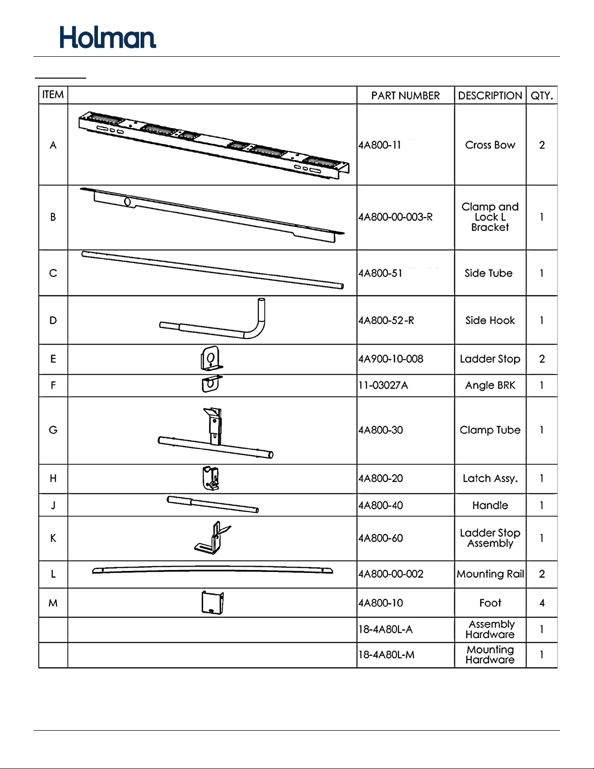
Parts List ........................................................................................................................................................... 2
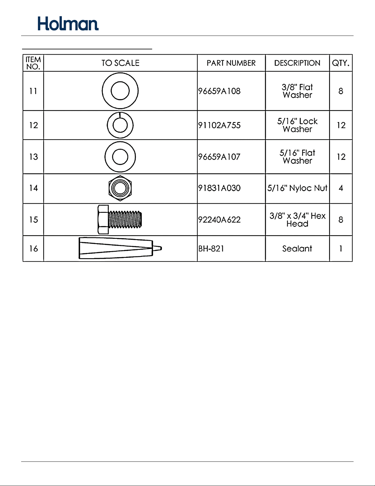
Hardware (18-4A80L-A) .................................................................................................................................... 3
Hardware (18-4A80L-M) ................................................................................................................................... 4
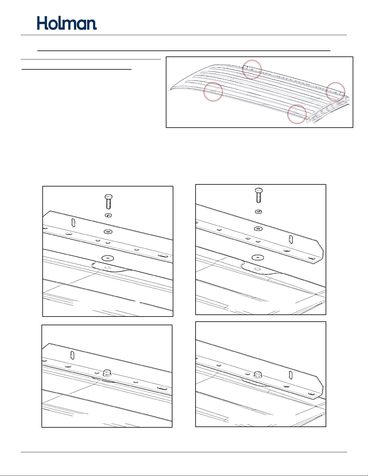
ProMaster City Installation ............................................................................................................................... 6
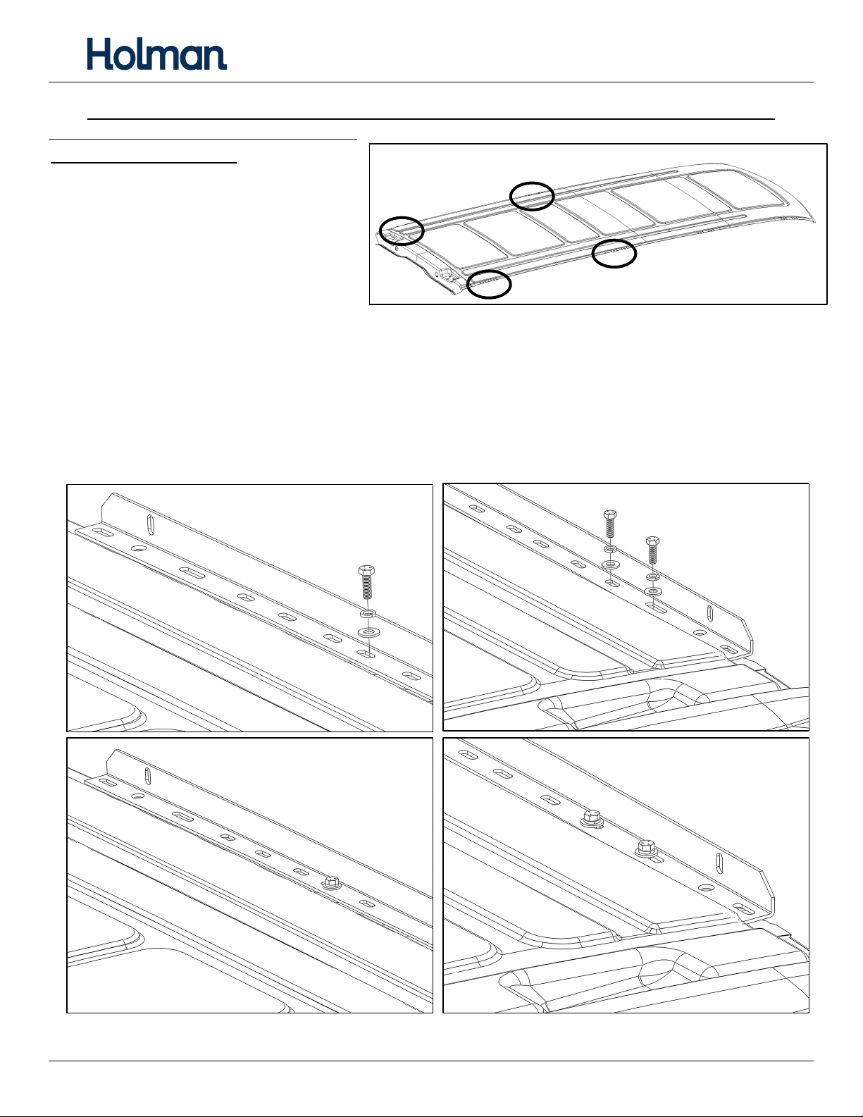
NV200/City Express Installation ....................................................................................................................... 7
Transit Connect Installation ............................................................................................................................. 8
Metris Rail Installation ..................................................................................................................................... 9
Assembly Instructions
Step 1 – Mount Feet to Rails ................................................................................................................... 10
Step 2 – Install Feet to Bows ................................................................................................................... 10
Step 3 – Install End Stops ........................................................................................................................ 11
Step 4 – Mount Side Tube ....................................................................................................................... 12
Step 5 – Assemble Clamp Mechanism .................................................................................................... 13
Step 6 – Mount Handle ........................................................................................................................... 14
Step 7 – Mount Latch .............................................................................................................................. 15
Step 8 – Mount Ladder Stop ................................................................................................................... 15
Before You Begin
• Read all instructions prior to assembling or installing any Holman product.
• Find your vehicle roof rail mounting prior to rack assembly.
• Be sure to put sealant around all threads entering cargo area and between the rubber spacer and roof of
vehicle to prevent water from leaking into cargo area.
• DO NOT EXCEED MANUFACTURERS WEIGHT CAPACITY FOR ROOF.
• Be sure to adjust ladder clamps accordingly to secure ladder firmly to rack. To adjust, refer to Clamp
and Lock adjustment guide.

Instructions – 4A80L
For Technical Support Call: 800-343-7486 Monday-Friday 7AM - 4 PM (PST) Page 2
Parts List

Instructions – 4A80L
For Technical Support Call: 800-343-7486 Monday-Friday 7AM - 4 PM (PST) Page 3
Hardware (18-4A80L-A)

Instructions – 4A80L
For Technical Support Call: 800-343-7486 Monday-Friday 7AM - 4 PM (PST) Page 4
Hardware (18-4A80L-M)

Instructions – 4A80L
For Technical Support Call: 800-343-7486 Monday-Friday 7AM - 4 PM (PST) Page 5
Hardware (18-4A80L-M) (Continued)

Instructions – 4A80L
For Technical Support Call: 800-343-7486 Monday-Friday 7AM - 4 PM (PST) Page 6
DO NOT EXCEED MANUFACTURERS WEIGHT CAPACITY FOR ROOF
ProMaster City Installation
• Locate 6 mounting locations shown
on roof of van.
• Install mounting rail as shown using
M6 x 22mm bolts with 1/4” lock
washers and 1/4” flat washers.
• In most installs, the rail upright is to
the outside of the van.
• Be sure to put rubber washer between the mounting rail and the roof to ensure sealing.
• Place sealant on and around threads to seal roof. (Passenger side shown)
FRONT EXPLODED
MID EXPLODED
REAR EXPLODED
FRONT TIGHTENED
MID TIGHTENED
REAR TIGHTENED

Instructions – 4A80L
For Technical Support Call: 800-343-7486 Monday-Friday 7AM - 4 PM (PST) Page 7
DO NOT EXCEED MANUFACTURERS WEIGHT CAPACITY FOR ROOF
NV200/City Express Installation
• Locate 4 mounting locations shown on
roof of van.
• Install mounting rail as shown using
M8 x 25mm bolts with 5/16” lock washers
and 5/16” flat washers.
• In most installs, the rail upright is to the
outside of the van.
• Mount rail so there is about 1” from the rear door opening.
• Be sure to put rubber washer between the mounting rail and the roof to ensure sealing.
• Place sealant on and around threads to seal roof. (Passenger side shown)
Note: Additional M8 x 20mm flat head screws are provided if mounting feet interferes with bolts.
REAR EXPLODED
FRONT EXPLODED
FRONT TIGHTENED
REAR TIGHTENED

Instructions – 4A80L
For Technical Support Call: 800-343-7486 Monday-Friday 7AM - 4 PM (PST) Page 8
DO NOT EXCEED MANUFACTURERS WEIGHT CAPACITY FOR ROOF
Transit Connect Installation
• Locate 4 mounting locations shown on
roof of van.
• Be sure to put rubber washer between the
mounting rail and the roof to ensure
sealing.
• In most installs, the rail upright is to the
outside of the van.
• Mount rail so there is about 1” from the rear door opening.
• Install mounting rail as shown using M8 x 25mm bolts and 5/16” flat washers on the outside. Use the
fender washer and M8 lock nut on the inside of the van.
• Place sealant on and around threads to seal roof. (Passenger side shown)
Note: Additional M8 x 20mm flat head screws are provided if mounting feet interferes with bolts.
FRONT
EXPLODED
REAR
EXPLODED
FRONT TIGHTENED
REAR TIGHTENED

Instructions – 4A80L
For Technical Support Call: 800-343-7486 Monday-Friday 7AM - 4 PM (PST) Page 9
DO NOT EXCEED MANUFACTURERS WEIGHT CAPACITY FOR ROOF
Metris Rail Installation
• Locate 6 mount locations on van roof, 4
rear and 2 mid-roof, as shown.
• Remove plastic cap in these locations
indicated to expose threads in the roof.
• Place the rail on the roof so the holes
align with the threaded holes in roof
and with approximately 5” between the rear of the rail and the rear door opening. In most installs, the rail
upright flange is to the outside of the van.
• Insert rubber washer between the mounting rail and the roof to ensure sealing.
• Apply sealant on and around threaded holes and bolt threads to seal roof. (Passenger side shown)
• Install mounting rail as shown using M6 x 22mm bolts, 1/4” lock washers, and 1/4” flat washers on the
outside. Be sure to apply sealant around bolts as you fasten them.
FRONT EXPLODED
REAR EXPLODED
REAR TIGHTENED
FRONT TIGHTENED

Instructions – 4A80L
For Technical Support Call: 800-343-7486 Monday-Friday 7AM - 4 PM (PST) Page 10
Assembly Instructions
Step 1 – Mount Feet to Rails
• Place both bows on top of installed rails. Bolt feet to rails using 5/16” x 1” hex head, two 5/16” flat
washers and a 5/16” lock nut.
• Typically, the ladder hooks go on the driver side of vehicle.
• Snug tighten, but allow movement.
Step 2 – Install Feet to Bows
• Place the bows and center on top of the previously installed feet. The same slot should be used at both
ends of the bows.

Instructions – 4A80L
For Technical Support Call: 800-343-7486 Monday-Friday 7AM - 4 PM (PST) Page 11
• Use a 3/8” x 3/4" hex head bolt, 3/8” lock washers and a 3/8” flat washer to bolt foot to cross member.
• DO NOT TIGHTEN at this point.
• Feet can be installed as shown below or reverse depending on how you mounted the rail.
• Snug tighten, but allow movement.
Step 3 – Install End Stops
NOTE: Skip installing the ladder stops if adding
4A81L.
• Use two 5/16” carriage bolts,
5/16” washers and a 5/16” lock nuts to bolt
end stops to one end of each bow, opposite
to clamping mechanism.
• TIGHTEN.
FEET INWARD
FEET REVERSED

Instructions – 4A80L
For Technical Support Call: 800-343-7486 Monday-Friday 7AM - 4 PM (PST) Page 12
Step 4 – Mount Side Tube
• Assemble the side tube.
• Place sealant around the
connection of the two tubes.
• While still malleable, place the side
tube assembly on top of the
installed bows. Have the bend
towards the front and outside of
the vehicle as shown.
• Mount angle bracket at the rear of the tube as shown. Leave one square slot open at rear of side tube.
• Bolt angle bracket to the front and rear bow using 5/16” x 2” carriage bolt, a 5/16” flat washer and a
5/16” lock nut.
• Snug tighten, but allow movement.

Instructions – 4A80L
For Technical Support Call: 800-343-7486 Monday-Friday 7AM - 4 PM (PST) Page 13
Step 5 – Assemble Clamp Mechanism
• Place the angle bracket on top of the installed bows with the long flange towards the center of the
vehicle. Do NOT install any hardware.
• Insert plastic bushings into the angle bracket and the ladder stop installed in Step 4, with the large flanges
of the bushings towards each other and to the inside of the brackets as shown.
• Insert the clamp tube into the previously installed bushings in the prientation shown.

Instructions – 4A80L
For Technical Support Call: 800-343-7486 Monday-Friday 7AM - 4 PM (PST) Page 14
• Bolt the angle bracket to the
front and rear bow using
3/8” x 1” carriage bolts, 3/8” flat
washers and a 3/8” lock nuts as
shown.
• Be sure the bushings CANNOT
come out.
• TIGHTEN.
Step 6 – Mount Handle
• Bolt the handle to the clamp tube using a 3/8” x 3” hex head, a 3/8” flat washer, 3/8” nylon washer, a
3/8” curved washer and a 3/8” lock nut. The nylon washer goes in between the clamp tube and the
handle. The curved washer fits the contour of the tube on the handle.
• TIGHTEN, but do not over tighten.

Instructions – 4A80L
For Technical Support Call: 800-343-7486 Monday-Friday 7AM - 4 PM (PST) Page 15
Step 7 – Mount Latch
• Bolt the latch to the round tube installed in Step 4 through the vacant slot using 5/16” x 2” carriage bolt,
5/16” flat washer and a 5/16” lock nut.
• TIGHTEN.
Step 8 – Mount Ladder Stop
• Bolt the ladder stop to the front bow in the orientation shown using two 3/8” x 1” carriage bolts, two 3/8”
flat washers and two 3/8” nyloc nuts.
• Adjust clamp on bracket to fit firmly against your ladder.
• TIGHTEN.
• After installation, adjust clamps to fit firmly against the ladder.

Instructions – 4A80L
For Technical Support Call: 800-343-7486 Monday-Friday 7AM - 4 PM (PST) Page 16
• Adjust clamps to fit firmly against the ladder.
GO BACK AND ENSURE ALL HARDWARE IS TIGHT
INSTALLATION IS NOW COMPLETE.
Table of contents
Other Holman Automobile Accessories manuals
Popular Automobile Accessories manuals by other brands

Audi
Audi e-tron Sportback (GE) 2020 installation instructions

Victory 4x4
Victory 4x4 200 Series Install instructions

Car-Interface
Car-Interface TV-Free CI-TF-NTG3 manual

Yakima
Yakima Bail Adapter instructions

Direction Plus
Direction Plus Fuel Manager FM100 installation guide

DICE
DICE Interface for iPod Installation guide & user manual