Dolphin DOLCWIUHF-910 User manual

INSTALLATION MANUAL
UHF LONG RANGE READER
(DOLCWIUHF-910)

User Manual of DOLCWIUHFP
1
Content
1 Introduction.................................................................................................................................... 2
1.1 Functions........................................................................................................................................ 2
1.1.1 Working principle.................................................................................................................... 2
1.1.2 Working Mode ........................................................................................................................ 2
1.1.3 Parameters .............................................................................................................................. 3
1.2 System Description......................................................................................................................... 3
1.2.1 Components............................................................................................................................ 3
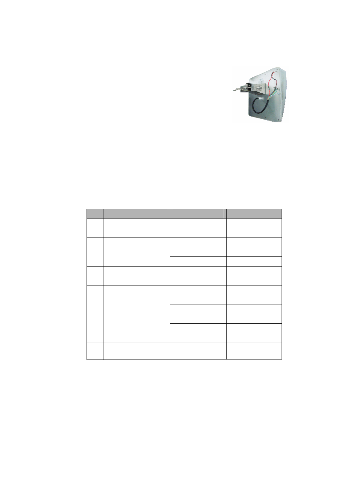
1.2.2 Host......................................................................................................................................... 4
1.2.3 Interface.................................................................................................................................. 4
1.2.4 LED Indicator ........................................................................................................................... 4
1.2.5 Buzzer...................................................................................................................................... 5
1.2.6 Label........................................................................................................................................ 5
1.3 Cautions before Using ................................................................................................................... 5
2 Reader Installation.......................................................................................................................... 6
2.1 Installation Overview ..................................................................................................................... 6
2.2 Installation Summary ..................................................................................................................... 6
2.3 Side Installation ............................................................................................................................. 7
2.3.1 Overview ................................................................................................................................. 7
2.3.2 Instruction............................................................................................................................... 7
2.3.3 Notice...................................................................................................................................... 8
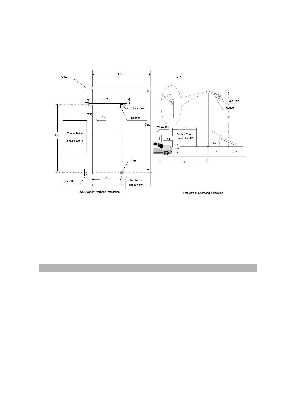
2.4 Overhead Installation .................................................................................................................... 8
2.4.1 Overview ................................................................................................................................. 8
2.4.2 Instruction............................................................................................................................... 9
2.4.3 Notice...................................................................................................................................... 9
1 Tag Installation ........................................................................................................................ 10
3.1 Overview ...................................................................................................................................... 10
3.2 Instruction .................................................................................................................................... 10
Appendix 1 How to check the performance simply? ........................................................................ 13

User Manual of DOLCWIUHFP
2
This device complies with parts 15 of the FCC Rules. Operation is subject to the following two
conditions: (1) This device may not cause harmful interference, and (2) This device must accept
any interference received, including interference that may cause undesired operation.
Changes or modification not expressly approved by the party responsible for compliance could
void the user’s authority to operate the equipment.
FCC Radiation Exposure Statement:
This equipment complies with FCC Radiation exposure limits set forth an uncontrolled
environment. This equipment should be installed and operated with minimum distance 20cm the
radiator &your body.
This transmitter must not be co-located or operating in conjunction with any other antenna or
transmitter.
1 Introduction
1.1 Functions
1.1.1 Working principle
directs the RF module to generate an RF signal,
which is broadcast through the internal antenna. Entering the
s reading range, a Transmitter Solutions RFID tag installed on a vehicle or other
object to be tracked adds its programmed identification information to the signal and reflects the signal
back to the . The
receives this modified or modulated signal, and decodes the tag data carried by the reflected signal
and transmits this data to a local host computer or process through specified the communication
port.
1.1.2 Working Mode
has two working mode. one is Interval Scan
Mode ,In this mode ,if reader Power on ,it will scan the tag intermittently The other mode is
Trigger Mode, in this mode, only if the voltage of the Trigger Pin is logic 0,the reader begins to
scan the tag automatically.
When reader enters into the scanning status, it will capture the programmed identification
information of the tags which within s read range automatically, and
transmits the data to a local host computer or process through the specified communication
interface ( Wiegand 26/34, RS232 or RS485).
The default working mode of is Interval Scan Mode
and specified Wiegand 26 as the communication interface. if need preconfigured to Trigger Mode
or other communication interface, please consult with the Transmitter Solutions before purchasing.
Transmitter Solutions DOLCWIUHFP
Transmitter Solutions DOLCWIUHFP Transmitter Solutions DOLCWIUHFP
Transmitter Solutions
DOLCWIUHFP
DOLCWIUHFP

User Manual of DOLCWIUHFP
3
1.1.3 Parameters
The parameters of Transmitter Solutions DOLCWIUHFP Table 1.1.3-1
Table 1.1.3-1
1.2 System Description
1.2.1 Components
The package of contents the components list in the
Table 1.2.1-1.
Table1.2.1-1
No Component Specification Quantity Remark
1Host 370* 360 * 96 mm 1 PC With Fixed Holder
2RS232 Cable 1 PC
3Test Tag 86 * 54 * 1.0 mm 1 PC Optional
4Definition of Connection Pins 1 PC
5Packing List 1 PC
No Parameter Value
1Operating Frequency 902928 MHz FHSS
2Transmitter Power 0.5 to 2W (programmed by software)
3Supply Voltage 10~25 VDC +5%/-1%, Ripple: maximum 50 mV
4Communication Rates 9600 bps
5Power Consumption Maximum 10 W
6Interfaces Optional Wigand 34, RS232, RS485
7Overall Size 370* 360 * 96 mm
8Package Size 430 * 420 * 190 mm
9Net Weight: 3.0 KGS
10 Operating Temperature -20°C to +70°C
11 Storage Temperature -40°C to +90°C
Transmitter Solutions DOLCWIUHFP

User Manual of DOLCWIUHFP
4
1.2.2 Host
Over view Side view Back view
1.2.3 Interface
can be able to provide 5 group interface, for details please refer
to
Table 1.2.3-1
Table 1.2.3-1 Definition of the Interface
No Interface Type Definition Color
+12 V Red
1Power Pins GND Black
Wiegand 0 Purple
Wiegand 1 Green
Ground Yellow
2Wiegand Pins
Trigger Orange
GND Yellow
3Trigger Pins
232 (RX) Blue
232 (TX) Grey
GND Black
4RS232 Pins
485 +
5RS485 Serial Port pins
6Shielding Wire
485 - Light Green
White
GND Yellow
Earth Ground Yellow Embeded
Green (Thick)
1.2.4 LED Indicato
Please make sure all connections are correct before turning on power!
r
There are two rows LED indicators on the , when
Transmitter Solutions DOLCWIUHFP

User Manual of DOLCWIUHFP
5
Red LED lighting means the is power on, while Blue LED lighting means the
captures the data of the tag,
1.2.5 Buzzer
When captures the data of the tag, the buzzer will beep.
1.2.6 Label
No Label Type Definition Position
1SN Label The serial number of the host Back Board
2Interface Label The specified communication interface of the host Back Board
3Capital Letter Label A or B or C or D or E Back Board
4Mode Interval Scan or Trigger Mode Back Board
Remark:
1. The SN label is the identification of each reader, don t tear off during using.
2. Please check the interface configuration with the Interface Label, if not correct, please contact with
Transmitter Solutions.
3. Don t install two hosts with the same Capital Letter Label within 20 meters scope.
4. Trigger Pins reserved for Trigger Mode only.
1.3 Cautions before Using
1. Please use the 12V 4A DC Power for connecting the host with the power.
2. If the DC Power is not waterproof, it is suggested to insert into the Ticket Box or be
covered.
3. The power cord which connected DC Power and the 120V AC Power needs to be
connected the ground wire to prevent lightning strikes.
4. When extending power:
• Up to 100 feet, use 18 AWG, 600 volt insulated wire
• Up to 200 feet, use 16 AWG, 600 volt insulated wire
THE PROPER WIRING IS CRITICAL!
5. Wiegand wire runs are 500 feet maxium. Use 6-conductor stranded wire with overall shield.
18, 20, 22 or 24 gauge is preferred.
DOLCWIUHFP
DOLCWIUHFP
DOLCWIUHFP

User Manual of DOLCWIUHFP
6
2 Reader Installation
2.1 Installation Overview
The Reader has been designed with easy installation in mind. The Figure 2.1-1 provides you
with any details that you will need to know.
Figure 2.1-1 Installation
2.2 Installation Summary
There are two ways for installing by install position.
One installs on the side of the lane which we called Side Installation, while the other installs on
the overhead of the lane which we called Overhead Installation. For details please refer to the
Table 2.2-1
Table 2.2-1
Install Way Advantage Disadvantage
Side Installation 1. Easy to install with the pole
2. Easy for maintenance
1.The read range is subject to the install height & the
angle of the reader
2. The tag should installed to the side near the reader
Overhead Installation 1. The reader range is larger & wider
2. The tag position is more flexible
1. It‘s not easy for maintenance due to the install
height of the reader.
2. The extension power wire & communication wire
requires longer & thicker
2.2 M
Transmitter Solutions DOLCWIUHFP

User Manual of DOLCWIUHFP
7
When the site meets following conditions, we suggest choosing the Overhead Installation way, otherwise
choosing the Side Installation way:
1. There are many types of car, especially with both large vehicle and small car;
2. The position of the tag is different from different type of vehicles;
3. The drive position is available for both left and right side
2.3 Side Installation
2.3.1 Overview
Take a simple parking lot for example: the width of the lane is 3.5 M, while the distance
between Gate and Ticket Box is 5 M. The reader is expected to be placed to allow time for the
gate to open so the car can roll through without stopping while not allowing room for an untagged
car to be between the car being read and the gate. There 2 opinions position for installing Reader,
for the details please refer to the Figure 2.3.1-1
Figure 2.3.1-1
2.3.2 Instruction
The instruction mentioned in the Table 2.3.2-1 is based on the example showed on the Figure
2.3.1-1, if not suitable for your site, you can contact with Transmitter Solutions for assistance.

User Manual of DOLCWIUHFP
8
Table 2.3.2-1
Description Position A Position B
Install Height Over 2.2 m (see the Left View of Position B in Figure 2.3.1-1)
Pole Position (H) Over 0.25 m horizontal far from the edge of the lane (See Over View of Side
Installation in Figure 2.3.1-1
Pole Position (V) 1.0 m far in vertical from the Gate 1.0 M far in vertical from the Ticket Box
Offset Angle with Lane About 30ºAbout 60º
Offset Angle with Pole About 0ºAbout 15º
2.3.3 Notice
1. If the DC Power is not waterproof, it is suggested to insert into the Ticket Box or be
covered.
2. The dia of the extension power core should be 1.5 mm"if the length is over 5.0 m.
3. The data wire should be with shielding layer and should be connected with the GND to
avoid any interference.
4. Adjust the reader range to make sure the tag can be detected when the vehicle with the tag
is approaching ticket box and within one lane area only, so that there is only one vehicle and one
tag in the operation area to avoid any wrong operation.
2.4 Overhead Installation
2.4.1 Overview
Take a simple parking lot for example; the width of the lane is 3.5 M, while the distance
between Gate and Ticket Box is 5 M. The reader is expected to be placed to allow time for the
gate to open so the car can roll through without stopping while not allowing room for an untagged
car to be between the car being read and the gate. For the details please refer to the Figure 2.4.1-1

User Manual of DOLCWIUHFP
9
Figure2.4.1-1
2.4.2 Instruction
The instruction mentioned in the Table 2.4.2-1 is based on the example showed on the Figure
2.4.1-1, if not suitable for your site, you can contact with Transmitter Solutions for assistance.
Tabel 2.4.2-1
Description Overhead Installation
Install Height Over 5.0 m (See the Left View of Overhead Installation in the Figure 2.4.1-1)
Pole Type L type as the Left View of Overhead Installation in the Figure 2.4.1-1)
Pole Position(H) Over 0.25 m horizontal far from the edge of the lane (See Over View of Side
Installation in Figure 2.4.1-1
Pole Position(V) 1.0 m far in vertical from the Gate
Offset Angle with Pole About 25º(see figure 2.4.1-1)
Reader position (H) The center of the Reader is 1.75 m far from the edge of the Lane in horizontal
2.4.3 Notice
1. If the DC Power is not waterproof, it is suggested to insert into the Ticket Box or be
covered.
2. The dia of the extension power wire should be 2.0 mm"if the length is over 10.0 m.

User Manual of DOLCWIUHFP
10
3. The data wire should be with shielding layer and should be connected with the GND to
avoid any interference.
4. Adjust the reader range to make sure the tag can be detected when the vehicle with the tag
is approaching ticket box and within one lane area only, so that there is only one vehicle and one
tag in the operation area to avoid any wrong operation.
1 Tag Installation
3.1 Overview
WINGSAFE provides 3 types of tag according to different demands:
Type Photo Suitable Way
Card
1. Fixed with card holder
2. Handheld by user
Sticker 1. Stick on the surface of the glass
Metal Tag 1. Fixed on the surface of the metal
3.2 Instruction
3.2.1 Card
3.2.1.1 Fixed with card holder
Transmitter Solutions provides 2 types of card holder according to different demands:
Type Photo Suitable Way
Fixed Holder Fixed on the windows, see the
remark
Rotatable
Holder Fixed on the driver platform

User Manual of DOLCWIUHFP
11
3.2.1.2 Installation for Tags
For the vehicles without metalized windshield, you can choose one of six places showed on
the figure 3.2.1-1 to install
For the vehicles with the pre-configured metalized windshield, it should have a reserved area
with 120(L) * 70(W) mm that not metalized for RFID tags according to the European Standard,
usually in the place B, so you can install the tag on this reserved area.
For the vehicles with the after-sale metalized windshield, you can choose one of six places
showed on figure 3.2.1-1 to cut off the metallic coat with a 120(L) * 70(W) mm area
For optimum performance, choose the placement A or E if the antenna of the reader in the left
position of the windshield; choose the placement C or D if the antenna in the right position of the
windshield; while choose placement B or F if the antenna in the overhead of the traffic lane.
Figure 3.2.1-1
3.2.1.3 Installation for card
The card is designed to install on the front of the driver platform, the base of the
card can be adjusted to make sure the front surface of the tag is face to the front surface
of the reader.
Remark: When there is a metalized windshield, the read range of the reader will be affected.
Please test the performance before installation
3.2.1.4 Holding the card by hand
Choose the correct way with ticket #!$ for holding card. For details, please see figure
3.2.1.4-1
Figure 3.2.1.4-1

User Manual of DOLCWIUHFP
12
3.2.2 Sticker
The install way is same as card holder, for details refer to 3.2.1.2. Please note that the
tag need to be used by stick on the surface of the window or headlights and cannot
able to reuse if rip off. Please test the performance before installation.
3.2.3 Metal Tag
It designed for License plate use only. Use the screws to fix the tag on the bottom of
the License plate

User Manual of DOLCWIUHFP
13
Appendix 1 How to check the performance simply?
Purpose: When a malfunction occurs during the using, the follow steps will help you to check the
performance of the reader simply.
1. Test Sites: Open area without any barrier or block.
2. Reader Install Height: Over 2 Meter and power the reader with Power Adapter & Power Code
enclosed the package.
3. Test Tag: use the tag enclosed the package
4. Tag Install: by hand, use the correct way as figure 3.2-3
5. Test Method: Keep the front surface of the tag parallel to the front surface of the reader.
Move the tag from the near to the distant by the horizontal line (see as the figure
Appendix-1) untilthe tag can not be detected by the reader. The line distance between the
reader and the tag is the MAX Distance.
6: When the MAX Distance is over 9 meters, and the reading signal of the reader is stable &
continuous, the read performance of the reader is OK.
Figure-Appendix-1
9 meters
Table of contents
Popular Receiver manuals by other brands

Williams Sound
Williams Sound PPA VP 37 Manual and user guide

Marantz
Marantz SR5008 Easy setup

Magenta Research
Magenta Research MultiView II AK600DP Installation and user guide

Sony
Sony HCD-CX4iP Service manual

punch
punch PMX-3 Installation & operation

Cambridge Audio
Cambridge Audio AZUR 651A Service manual